steering Ram ProMaster City 2020 Owner's Guide
[x] Cancel search | Manufacturer: RAM, Model Year: 2020, Model line: ProMaster City, Model: Ram ProMaster City 2020Pages: 350, PDF Size: 13.27 MB
Page 209 of 350
206 IN CASE OF EMERGENCY
FUSESUnderhood Fuses
The Front Distribution Unit is located on the right side of the
engine compartment, next to the battery. To access the fuses,
remove fasteners and remove the cover.
Front Distribution Unit
The ID number of the electrical component corresponding to
each fuse can be found on the back of the cover.WARNING!
• When replacing a blown fuse, always use an appro -
priate replacement fuse with the same amp rating as the
original fuse. Never replace a fuse with another fuse of
higher amp rating. Never replace a blown fuse with
metal wires or any other material. Do not place a fuse
inside a circuit breaker cavity or vice versa. Failure to
use proper fuses may result in serious personal injury,
fire and/or property damage.
• Before replacing a fuse, make sure that the ignition is off and that all the other services are switched off and/
or disengaged.
• If the replaced fuse blows again, contact an authorized dealer.
• If a general protection fuse for safety systems (air bag system, braking system), power unit systems (engine
system, transmission system) or steering system blows,
contact an authorized dealer.
2020_RAM_PROMASTER_CITY_OM_USA=GUID-7B6A7FCA-79B0-423F-95C5-ED2A949C3D13=1=en=.book Page 206
Page 211 of 350

208 IN CASE OF EMERGENCY
F20–30 Amp Green Rear Defroster (If Equipped)
F21 –5 Amp Tan Key Unlock
F22 –10 Amp Red
Primary ECM Loads
F23 –20 Amp Yellow BSM System
F24 –5 Amp Tan BSM System, Positive Key and Steering Angle Sensor
F30 –15 Amp Blue 2nd Instrument Panel Power Outlet
F83 20 Amp Yellow –Fuel Pump
F84 –15 Amp Blue AT Module
F85 –15 Amp Blue Rear Power Outlet 12 Volts
F86 –15 Amp Blue IP Power Outlet 12 Volts
F87 –5 Amp Tan IBS
F88 –7.5 Amp Brown External Mirror Defrost (If Equipped)
Cavity
Maxi Fuse Mini Fuse Description
2020_RAM_PROMASTER_CITY_OM_USA=GUID-7B6A7FCA-79B0-423F-95C5-ED2A949C3D13=1=en=.book Page 208
Page 238 of 350
IN CASE OF EMERGENCY 235
IGNITION KEY REMOVAL OVERRIDE
This vehicle is equipped with a Key Ignition Park Interlock
which requires the transmission to be in PARK (P) before the
ignition switch can be turned to the LOCK/OFF (key
removal) position. To remove the key manually, proceed as
follows:
1. Firmly apply the parking brake.
2. Remove the Allen Key located in the rear cargo area, inthe tool bag (if equipped) or on the left side in the cargo
box.
3. Unlock the steering column, pull the tilt/telescoping control handle down. 4. Pull the steering wheel outward until it is in the end of the
travel position, then lock the steering column in position,
push the control handle up until fully engaged.
5. Using the Allen Key, undo the lower steering column cover screws, and remove the lower cover.
Lower Steering Column Screw Locations
6. Pull the release tab downwards using one hand and with the other one remove the key, sliding it outwards.
CAUTION!
Driving with a hot cooling system could damage your
vehicle. If the temperature gauge reads HOT (H), pull
over and stop the vehicle. Idle the vehicle with the air
conditioner turned off until the pointer drops back into
the normal range. If the pointer remains on HOT (H),
and you hear continuous chimes, turn the engine off
immediately and call for service.
6
2020_RAM_PROMASTER_CITY_OM_USA=GUID-7B6A7FCA-79B0-423F-95C5-ED2A949C3D13=1=en=.book Page 235
Page 239 of 350
236 IN CASE OF EMERGENCY
Release Tab Location
7. Once the key is removed, reinstall the steering column cover.
GEAR SELECTOR OVERRIDE
If a malfunction occurs and the gear selector cannot be
moved out of the PARK (P) position, you can use the
following procedure to temporarily move the gear selector:
1. Turn the engine OFF.
2. Firmly apply the parking brake.
3. Using a screwdriver or similar tool, carefully separate thegear selector boot from the center console.
Gear Selector Boot Location
4. Press and maintain firm pressure on the brake pedal.
CAUTION!
It is advisable to contact an authorized dealer to have the
reinstall procedure carried out. If you would like to
proceed in performing the reinstall procedure special
attention must be paid to the correct coupling of the
clips. Otherwise damage to the cover or noise might be
heard due to incorrect fastening of the lower cover.
2020_RAM_PROMASTER_CITY_OM_USA=GUID-7B6A7FCA-79B0-423F-95C5-ED2A949C3D13=1=en=.book Page 236
Page 240 of 350

IN CASE OF EMERGENCY 237
5. Insert a small screwdriver or a similar tool into the gearselector override access hole (at the right front corner of
the gear selector assembly), then push and hold the over -
ride release lever down. While holding the override
release lever down, push the lock button on the gear
selector and move the gear selector to the NEUTRAL (N)
position.
Gear Selector Override Access Hole
6. The vehicle may then be started in NEUTRAL (N).
7. Reinstall the gear selector boot.FREEING A STUCK VEHICLE
If your vehicle becomes stuck in mud, sand, or snow, it can
often be moved using a rocking motion. Turn the steering
wheel right and left to clear the area around the front wheels.
Push and hold the lock button on the gear selector. Then shift
back and forth between DRIVE (D) and REVERSE (R), while
gently pressing the accelerator. Use the least amount of accel -
erator pedal pressure that will maintain the rocking motion,
without spinning the wheels or racing the engine.
NOTE:
Shifts between DRIVE (D) and REVERSE (R) can only be
achieved at wheel speeds of 5 mph (8 km/h) or less. When -
ever the transmission remains in NEUTRAL (N) for more
than two seconds, you must press the brake pedal to engage
DRIVE (D) or REVERSE (R).
CAUTION!
Racing the engine or spinning the wheels may lead to
transmission overheating and failure. Allow the engine
to idle with the transmission in NEUTRAL for at least
one minute after every five rocking-motion cycles. This
will minimize overheating and reduce the risk of
transmission failure during prolonged efforts to free a
stuck vehicle.
6
2020_RAM_PROMASTER_CITY_OM_USA=GUID-7B6A7FCA-79B0-423F-95C5-ED2A949C3D13=1=en=.book Page 237
Page 248 of 350
SERVICING AND MAINTENANCE 245
ENGINE COMPARTMENT
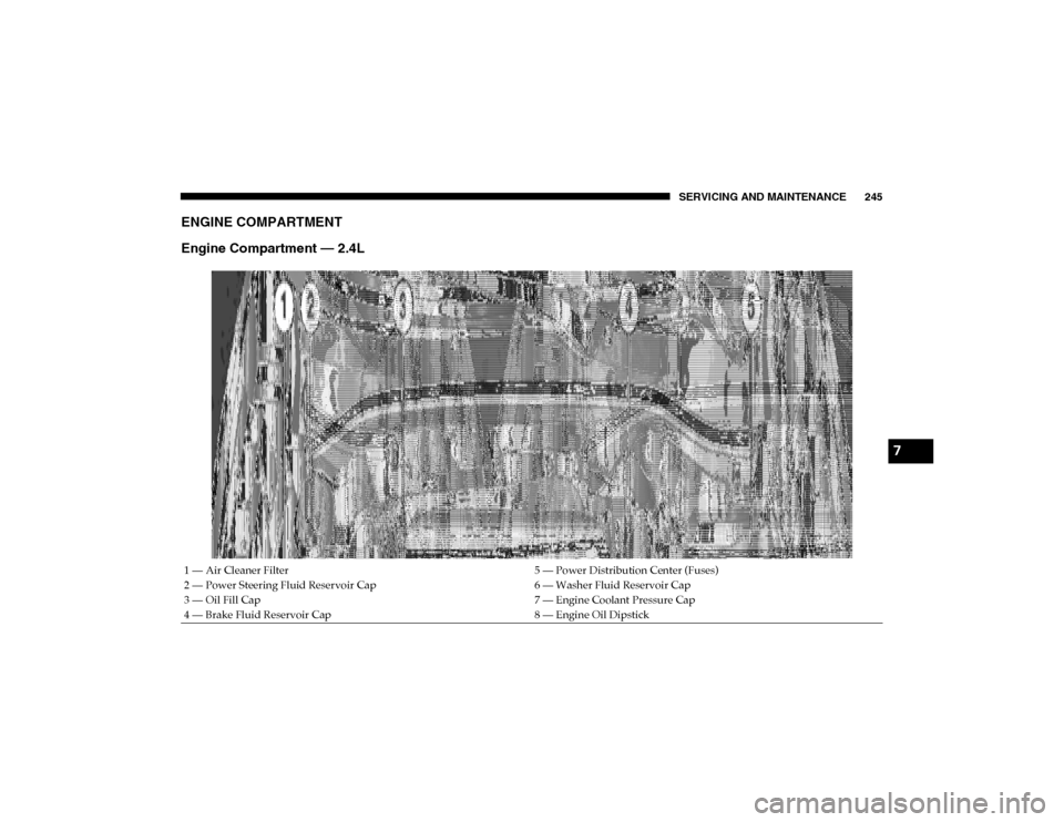
Engine Compartment — 2.4L
1 — Air Cleaner Filter5 — Power Distribution Center (Fuses)
2 — Power Steering Fluid Reservoir Cap 6 — Washer Fluid Reservoir Cap
3 — Oil Fill Cap 7 — Engine Coolant Pressure Cap
4 — Brake Fluid Reservoir Cap 8 — Engine Oil Dipstick
7
2020_RAM_PROMASTER_CITY_OM_USA=GUID-7B6A7FCA-79B0-423F-95C5-ED2A949C3D13=1=en=.book Page 245
Page 264 of 350
SERVICING AND MAINTENANCE 261
Power Steering Fluid
Check the fluid level with the vehicle on flat ground and
engine cold. Fluid should be between MIN and MAX refer-
ences on the reservoir body.
The level may go over the MAX line when oil is hot.
If topping off is required, make sure the oil you use is
approved. Refer to “Fluids And Lubricants” in “Technical
Specifications” for further information. NOTE:
Power steering fluid consumption is very low. If you need to
top off your fluid often and multiple times, have your system
inspected by an authorized dealer.
Automatic Transmission
Selection Of Lubricant
It is important to use the proper transmission fluid to ensure
optimum transmission performance and life. Use only the
manufacturer's specified transmission fluid. Refer to “Fluids
And Lubricants” in “Technical Specifications” for fluid spec
-
ifications. It is important to maintain the transmission fluid
at the correct level using the recommended fluid.
NOTE:
No chemical flushes should be used in any transmission;
only the approved lubricant should be used.
• Overfilling the brake fluid reservoir can result in
spilling brake fluid on hot engine parts, causing the
brake fluid to catch fire. Brake fluid can also damage
painted and vinyl surfaces, care should be taken to
avoid its contact with these surfaces.
• Do not allow petroleum based fluid to contaminate the brake fluid. Brake seal components could be damaged,
causing partial or complete brake failure. This could
result in a collision.
WARNING! (Continued)WARNING!
Because it is flammable, do not allow the power steering
fluid to come into contact with hot engine parts
7
2020_RAM_PROMASTER_CITY_OM_USA=GUID-7B6A7FCA-79B0-423F-95C5-ED2A949C3D13=1=en=.book Page 261
Page 279 of 350
276 SERVICING AND MAINTENANCE
(Continued)
Tires — General Information
Tire Pressure
Proper tire inflation pressure is essential to the safe and satis-
factory operation of your vehicle. Four primary areas are
affected by improper tire pressure:
• Safety
• Fuel Economy
• Tread Wear
• Ride Comfort and Vehicle Stability
Safety
Both underinflation and overinflation affect the stability of
the vehicle and can produce a feeling of sluggish response or
over responsiveness in the steering.
NOTE:
• Unequal tire pressures from side to side may cause erraticand unpredictable steering response.
• Unequal tire pressure from side to side may cause the vehicle to drift left or right.
WARNING!
• Improperly inflated tires are dangerous and can cause collisions.
• Underinflation increases tire flexing and can result in overheating and tire failure.
• Overinflation reduces a tire's ability to cushion shock. Objects on the road and chuckholes can cause damage
that result in tire failure.
• Overinflated or underinflated tires can affect vehiclehandling and can fail suddenly, resulting in loss of
vehicle control.
• Unequal tire pressures can cause steering problems. You could lose control of your vehicle.
• Unequal tire pressures from one side of the vehicle to the other can cause the vehicle to drift to the right or
left.
• Always drive with each tire inflated to the recom -
mended cold tire inflation pressure.
WARNING! (Continued)
2020_RAM_PROMASTER_CITY_OM_USA=GUID-7B6A7FCA-79B0-423F-95C5-ED2A949C3D13=1=en=.book Page 276
Page 284 of 350

SERVICING AND MAINTENANCE 281
tion placard or the Vehicle Certification Label for the size
designation of your tire. The Load Index and Speed Symbol
for your tire will be found on the original equipment tire
sidewall.
See the Tire Sizing Chart example found in the “Tire Safety
Information” section of this manual for more information
relating to the Load Index and Speed Symbol of a tire.
It is recommended to replace the two front tires or two rear
tires as a pair. Replacing just one tire can seriously affect
your vehicle’s handling. If you ever replace a wheel, make
sure that the wheel’s specifications match those of the orig-
inal wheels.
It is recommended you contact an authorized tire dealer or
original equipment dealer with any questions you may have
on tire specifications or capability. Failure to use equivalent
replacement tires may adversely affect the safety, handling,
and ride of your vehicle.WARNING!
• Do not use a tire, wheel size, load rating, or speed rating other than that specified for your vehicle. Some combina -
tions of unapproved tires and wheels may change suspen -
sion dimensions and performance characteristics,
resulting in changes to steering, handling, and braking of
your vehicle. This can cause unpredictable handling and
stress to steering and suspension components. You could
lose control and have a collision resulting in serious injury
or death. Use only the tire and wheel sizes with load
ratings approved for your vehicle.
• Never use a tire with a smaller load index or capacity, other than what was originally equipped on your
vehicle. Using a tire with a smaller load index could
result in tire overloading and failure. You could lose
control and have a collision.
• Failure to equip your vehicle with tires having adequate speed capability can result in sudden tire
failure and loss of vehicle control.
CAUTION!
Replacing original tires with tires of a different size may
result in false speedometer and odometer readings.
7
2020_RAM_PROMASTER_CITY_OM_USA=GUID-7B6A7FCA-79B0-423F-95C5-ED2A949C3D13=1=en=.book Page 281
Page 290 of 350

SERVICING AND MAINTENANCE 287
Dark Vapor Chrome, Black Satin Chrome, or Low Gloss
Clear Coat Wheels
Tire Chains (Traction Devices)
Due to limited clearance, tire chains or traction devices are
not recommended.
Tire Rotation Recommendations
The tires on the front and rear of your vehicle operate at
different loads and perform different steering, driving, and
braking functions. For these reasons, they wear at unequal
rates.
These effects can be reduced by timely rotation of tires. The
benefits of rotation are especially worthwhile with aggres-
sive tread designs such as those on all season type tires. Rota -
tion will increase tread life, help to maintain mud, snow and
wet traction levels, and contribute to a smooth, quiet ride.
Refer to the “Maintenance Plan” for the proper maintenance
intervals. The reasons for any rapid or unusual wear should
be corrected prior to rotation being performed.
CAUTION!
If your vehicle is equipped with these specialty wheels,
DO NOT USE wheel cleaners, abrasives, or polishing
compounds. They will permanently damage this finish
and such damage is not covered by the New Vehicle
Limited Warranty. HAND WASH ONLY USING MILD
SOAP AND WATER WITH A SOFT CLOTH. Used on a
regular basis; this is all that is required to maintain this
finish.
CAUTION!
Damage to the vehicle may result if tire chains are used.
7
2020_RAM_PROMASTER_CITY_OM_USA=GUID-7B6A7FCA-79B0-423F-95C5-ED2A949C3D13=1=en=.book Page 287