stop start RAM PROMASTER CITY 2021 Owner's Manual
[x] Cancel search | Manufacturer: RAM, Model Year: 2021, Model line: PROMASTER CITY, Model: RAM PROMASTER CITY 2021Pages: 280, PDF Size: 15.78 MB
Page 132 of 280
130MULTIMEDIA
Voice Command — If Equipped
About Voice command
Instead of pressing the touchscreen to control
your navigation system, you can use your voice
to control navigation.
For example, to switch to 2D view, you can say
“2D view”.
To view a list of available commands, press the
“Help” button in the Main menu and then press
“What can I say?”.
Using Voice Control The following example shows how to use voice
control to plan a journey to your Home address:
1. Push the Voice Recognition button on
the steering wheel to turn on the
microphone.
A screen will pop up with examples of com -
mands.
NOTE:
Press the Help button in the Main menu then
press “What can I say?” to see a full list of
commands.
2. When you hear a beep, say a command of your choice. For example, you can say
“Navigate home”.
NOTE:
For accurate results, speak normally without
trying to articulate words in an unnatural way. If
there is excessive road noise, for example, you
may need to speak directly into the microphone.
3. If the command is correct, say “Yes”. NOTE:
If the command is incorrect, say “No” and
repeat the command after you hear the prompt
and tone again. Your navigation system plans a
route from your current location to your destina-
tion. To stop your navigation system from
listening out for further commands, say
“Cancel”.
Guidance View
The guidance view is used to guide you along
the route to your destination. As soon as you
start driving, your navigation system will
immediately start guiding you to your
destination with spoken instructions and visual
instructions on the touchscreen. You can also
see your current location and details along your
route, including 3D buildings in some cities. The
guidance view is normally in 3D. To show a 2D
map with the map moving in your direction of
travel, change the 2D and 3D settings
Ú
page 135.
WARNING!
ALWAYS drive safely with your hands on the
wheel. You have full responsibility and
assume all risks related to the use of the
Uconnect features and applications in this
vehicle. Only use Uconnect when it is safe to
do so. Failure to do so may result in an
accident involving serious injury or death.
21_VM_OM_EN_USC_t.book Page 130
Page 138 of 280
136MULTIMEDIA
Appearance
To change how your navigation screen looks,
select “Appearance” in the settings menu. From
here, you can change these features:
Switch To Night Colors When Dark : Select
this setting to make your system automati -
cally switch to night colors when it gets dark.
Automatic Zoom : Select “Automatic Zoom” to
change how your system zooms in guidance
view when you approach a turn or intersec -
tion. Zooming in can make the turn or inter -
section easier to drive. The following options
are available:
Zoom in to next turn
Based on road type
None
Arrival Information
In the settings menu, select “Arrival
Information” to change the following settings:
Show Remaining Distance : Select this setting
to show the remaining distance left to travel
in the arrival information panel during navi -
gation.
Show Remaining Time : Select this setting to
show the remaining time left to travel in the
arrival information panel during navigation.
Switch Between Distance And Time Automat -
ically : Select this setting to control the auto -
matic switching between remaining distance
and remaining time in the arrival information
panel.
Show On Route
In the settings menu, select “Show On Route” to
see any of the following options in the route bar:
Parking : Select this setting to see parking lots
on your route.
Gas Stations: Select this setting to see gas
stations on your route.
Stops : Select this setting to see stops on your
route.
Show Previews Of Highway Exits
Select this setting to control the full screen
preview when you approach highway exits. Automatic Map View Switching
Automatic changing of views is on by default.
For example, when an alternative route is being
suggested, the map will automatically switch to
map view, and when you start driving, your map
will automatically switch to guidance view. You
can turn this feature off by selecting “Automatic
Map View Switching” in the settings.
Automatic Zoom
Select this setting to control the full screen
preview when you approach highway exits.
Guidance View Style
Select this setting to choose between 3D and
2D versions of the guidance view. Both the 2D
and 3D guidance views move in your direction
of travel.
In 3D guidance view, you can choose to use the
3D car icon or an arrowhead as the current
location indicator. By default, the 3D guidance
view shows the 3D car icon.
Voices Setting
Select this setting to change how instructions
are read out loud Ú
page 135.
21_VM_OM_EN_USC_t.book Page 136
Page 140 of 280
138MULTIMEDIA
Points Of Interest
About Points Of Interest
Points Of Interest (POI) are useful places on the
map.
Here are some examples:
Restaurants
Hotels
Museums
Parking lots
Gas stations
Emergency Services
Using POIs To Plan A Route
When you plan a route, you can use a POI for the
destination or as a stop along the route.
Using Search
1. Select “Search” on the Main Menu to begin a search. The search screen will open,
displaying the keyboard. Enter the name of
your desired destination. Your search
results will be displayed in two lists.
Addresses and city matches are shown in the list called “Addresses.” POIs, types of
POIs, and Places are shown in the list
called “Points of Interest.” You can also
select a POI category to only see POI
search results from that category.
2. Select the desired POI. The location will appear on the map. From here, you can
save the POI to “My Places,” use this POI as
a starting point, begin navigation to this
destination, or view more details about this
POI. By pressing “More Information,” you
can view the phone number and full
address of the POI.
3. If a route is already planned, you can add the location to your current route. To plan a
route to this destination, press the Drive
button on the touchscreen.
NOTE:
Your navigation system will calculate a route,
and guidance to your destination will begin.
Guidance view will begin as soon as you start
driving.
My Places
About My Places My Places provides an easy way to
select a location without the need to
enter the address or search for the
location. You can use My Places to
create a collection of useful or favorite
addresses.
The following items are always in My Places:
Home : Your home location can be your home
address or somewhere you often visit. This
feature provides an easy way to navigate
there.
Recent Destinations: Select this button to
select your destination from a list of locations
you have recently navigated to.
21_VM_OM_EN_USC_t.book Page 138
Page 148 of 280
146SAFETY
Electronic Brake Control (EBC) System
Your vehicle is equipped with an advanced
Electronic Brake Control (EBC) system that
includes the Brake Assist System (BAS),
Traction Control System (TCS), Hill Start Assist
(HSA), Electronic Stability Control (ESC),
Electronic Roll Mitigation (ERM) and Trailer
Sway Control (TSC). All systems work together to
enhance vehicle stability and control in various
driving conditions and are commonly referred to
as ESC.
Brake Assist System (BAS)
BAS is designed to optimize the vehicle’s
braking capability during emergency braking
maneuvers. The system detects an emergency
braking situation by sensing the rate and
amount of brake application and then applies
optimum pressure to the brakes. This can help
reduce braking distances. The BAS
complements the Anti-Lock Brake System
(ABS). Applying the brakes very quickly results
in the best BAS assistance. To receive the
benefit of the system, you must apply continuous braking pressure during the
stopping sequence (do not “pump” the brakes).
Do not reduce brake pedal pressure unless
braking is no longer desired. Once the brake
pedal is released, the BAS is deactivated.
Electronic Stability Control (ESC)
ESC enhances directional control and stability
of the vehicle under various driving conditions.
ESC corrects for over/under steering of the
vehicle by applying the brake of the appropriate
wheel to counteract the above conditions.
Engine power may also be reduced to help the
vehicle maintain the desired path.
Oversteer - when the vehicle is turning more
than appropriate for the steering wheel posi
-
tion.
Understeer - when the vehicle is turning less
than appropriate for the steering wheel posi -
tion.
ESC uses sensors in the vehicle to determine
the vehicle path intended by the driver and
compares it to the actual path of the vehicle.
When the actual path does not match the
intended path, ESC applies the brake of the
appropriate wheel to assist in counteracting the
oversteer or understeer condition.
WARNING!
The Brake Assist System (BAS) cannot
prevent the natural laws of physics from
acting on the vehicle, nor can it increase the
traction afforded by prevailing road
conditions. BAS cannot prevent collisions,
including those resulting from excessive
speed in turns, driving on very slippery
surfaces, or hydroplaning. The capabilities of
a BAS-equipped vehicle must never be
exploited in a reckless or dangerous manner,
which could jeopardize the user's safety or
the safety of others.
21_VM_OM_EN_USC_t.book Page 146
Page 150 of 280
148SAFETY
The ESC Activation/Malfunction Indicator Light
(located in the instrument cluster) starts to
flash as soon as the tires lose traction and the
ESC system becomes active. The ESC
Activation/Malfunction Indicator Light also
flashes when TCS is active. If the ESC
Activation/Malfunction Indicator Light begins to
flash during acceleration, ease up on the
accelerator and apply as little throttle as
possible. Be sure to adapt your speed and
driving to the prevailing road conditions.
The ESC OFF Indicator Light indicates
the Electronic Stability Control (ESC)
is in a reduced mode.
NOTE:
The ESC Activation/Malfunction Indicator
Light and the ESC OFF Indicator Light come
on momentarily each time the ignition switch
placed in the ON position.
Each time the ignition is placed in the ON
position, the ESC system will be on even if it
was turned off previously.
Electronic Roll Mitigation (ERM)
ERM anticipates the potential for wheel lift by
monitoring the driver’s steering wheel input and
the speed of the vehicle. When ERM determines
that the rate of change of the steering wheel
angle and vehicle’s speed are sufficient to
potentially cause wheel lift, it then applies the
appropriate brake and may also reduce engine
power to lessen the chance that wheel lift will
occur.
ERM can only reduce the chance of wheel lift
occurring during severe or evasive driving
maneuvers; it cannot prevent wheel lift due to
other factors, such as road conditions, leaving
the roadway, or striking objects or other
vehicles.
Hill Start Assist (HSA)
HSA is designed to assist the driver when
starting a vehicle from a stop on a hill. HSA will
maintain the level of brake pressure the driver
applied for a short period of time after the driver
takes their foot off of the brake pedal. If the
driver does not apply the throttle during this
short period of time, the system will release
brake pressure and the vehicle will roll down the
hill. The system will release brake pressure in
proportion to the amount of throttle applied as
the vehicle starts to move in the intended
direction of travel.
HSA Activation Criteria
The following criteria must be met in order for
HSA to activate:
The vehicle must be stopped.
The vehicle must be on a 5% (approximate)
grade or greater hill.
Gear selection matches vehicle uphill direc -
tion (i.e., vehicle facing uphill is in forward
gear; vehicle backing uphill is in REVERSE
gear).
WARNING!
Many factors, such as vehicle loading, road
conditions and driving conditions, influence
the chance that wheel lift or rollover may
occur. ERM cannot prevent all wheel lift or roll
overs, especially those that involve leaving
the roadway or striking objects or other vehi -
cles. The capabilities of an ERM-equipped
vehicle must never be exploited in a reckless
or dangerous manner which could jeopardize
the user's safety or the safety of others.
21_VM_OM_EN_USC_t.book Page 148
Page 163 of 280
SAFETY161
Supplemental Restraint Systems (SRS)
Some of the safety features described in this
section may be standard equipment on some
models, or may be optional equipment on
others. If you are not sure, ask an authorized
dealer.
The air bag system must be ready to protect you
in a collision. The Occupant Restraint Controller
(ORC) monitors the internal circuits and
interconnecting wiring associated with the
electrical Air Bag System Components. Your
vehicle may be equipped with the following Air
Bag System Components:
Air Bag System Components
Occupant Restraint Controller (ORC)
Air Bag Warning Light
Steering Wheel and Column
Instrument Panel
Knee Impact Bolsters
Driver and Front Passenger Air Bags
Seat Belt Buckle Switch
Supplemental Side Air Bags
Supplemental Knee Air Bags
Front and Side Impact Sensors
Seat Belt Pretensioners
Air Bag Warning Light
The Occupant Restraint Controller
(ORC) monitors the readiness of the
electronic parts of the air bag system
whenever the ignition switch is in the
AVV/START or MAR/ACC/ON/RUN position. If
the ignition switch is in the STOP/OFF/LOCK
position the air bag system is not on and the air
bags will not inflate. The ORC contains a backup power supply
system that may deploy the air bag system even
if the battery loses power or it becomes
disconnected prior to deployment.
The ORC turns on the Air Bag Warning Light in
the instrument panel for approximately four to
eight seconds for a self-check when the ignition
switch is in the MAR/ACC/ON/RUN position.
After the self-check, the Air Bag Warning Light
will turn off. If the ORC detects a malfunction in
any part of the system, it turns on the Air Bag
Warning Light, either momentarily or
continuously. A single chime will sound to alert
you if the light comes on again after initial
startup.
The ORC also includes diagnostics that will
illuminate the instrument panel Air Bag Warning
Light if a malfunction is detected that could
affect the air bag system. The diagnostics also
record the nature of the malfunction. While the
air bag system is designed to be maintenance
free, if any of the following occurs, have an
authorized dealer service the air bag system
immediately.
Failure to replace the seat belt assembly
could increase the risk of injury in colli
-
sions.
Do not use the Automatic Locking Mode to
restrain occupants who are wearing the
seat belt or children who are using booster
seats. The locked mode is only used to
install rear-facing or forward-facing child
restraints that have a harness for
restraining the child.
WARNING! (Continued)
6
21_VM_OM_EN_USC_t.book Page 161
Page 170 of 280
168SAFETY
Enhanced Accident Response System
In the event of an impact, if the communication
network remains intact, and the power remains
intact, depending on the nature of the event,
the Occupant Restraint Controller (ORC) will
determine whether to have the Enhanced
Accident Response System perform the
following functions:
Cut off fuel to the engine (if equipped)
Cut off battery power to the electric motor (if
equipped)
Flash hazard lights as long as the battery has
power
Turn on the interior lights, which remain on
as long as the battery has power or for
15 minutes from the intervention of the
Enhanced Accident Response System
Unlock the power door locks
Your vehicle may also be designed to perform
any of these other functions in response to the
Enhanced Accident Response System:
Turn off the Fuel Filter Heater, Turn off the
HVAC Blower Motor, Close the HVAC Circula -
tion Door
Cut off battery power to the:
Engine
Electric Motor (if equipped)
Electric Power Steering
Brake booster
Electric park brake
Automatic transmission gear selector
Horn
Front wiper
Headlamp washer pump
NOTE:
After an accident, remember to cycle the igni -
tion to the STOP/OFF position and remove the
key from the ignition switch to avoid draining
the battery. Carefully check the vehicle for fuel
leaks in the engine compartment and on the
ground near the engine compartment and fuel
tank before resetting the system and starting
the engine. If there are no fuel leaks or damage
to the vehicle electrical devices (e.g. headlights)
after an accident, reset the system by following
the procedure described below. If you have any
doubt, contact an authorized dealer.
Enhanced Accident Response System Reset
Procedure
In order to reset the Enhanced Accident
Response System functions after an event, the
ignition switch must be changed from ignition
AVV/START or MAR/RUN to ignition STOP/OFF.
Carefully check the vehicle for fuel leaks in the
engine compartment and on the ground near
the engine compartment and fuel tank before
resetting the system and starting the engine.
After a crash, if the vehicle will not start after
performing the reset procedure, the vehicle
must be towed to an authorized dealer to be
inspected and to have the Enhanced Accident
Response System reset.
21_VM_OM_EN_USC_t.book Page 168
Page 205 of 280
IN CASE OF EMERGENCY203
(Continued)
Insert the power plug into the vehicle power
outlet socket. Start the vehicle engine.
Push the Tire Service Kit power button on. The
electric compressor will be turned on, sealant
and air will inflate the tire.
Minimum 26 psi (1.8 bar) of pressure should be
reached within 20 minutes. If the pressure has
not been reached, turn off and remove the Tire
Service Kit, drive the vehicle 30 feet
(10 meters) back and forth, to better distribute
the sealant inside the tire.
Attach the clear flexible filling tube of the
compressor directly to the tire valve and repeat
the inflation process.
When the correct pressure has been reached,
start driving the vehicle to uniformly distribute
the sealant inside the tire. After 10 minutes,
stop and check the tire pressure. If the pressure
is below 19 psi (1.3 bar), do not drive the
vehicle, as the tire is too damaged, contact the
nearest authorized dealer.WARNING!
Do not attempt to seal a tire on the side of
the vehicle closest to traffic. Pull far enough
off the road to avoid the danger of being hit
when using the Tire Service Kit.
Do not use Tire Service Kit or drive the
vehicle under the following circumstances:
If the puncture in the tire tread is
approximately 1/4 inch (6 mm) or
larger.
If the tire has any sidewall damage.
If the tire has any damage from driving
with extremely low tire pressure.
If the tire has any damage from driving
on a flat tire.
If the wheel has any damage.
If you are unsure of the condition of the
tire or the wheel.
Keep Tire Service Kit away from open
flames or heat source.
A loose Tire Service Kit thrown forward in a
collision or hard stop could endanger the
occupants of the vehicle. Always stow the
Tire Service Kit in the place provided.
Failure to follow these warnings can result
in injuries that are serious or fatal to you,
your passengers, and others around you.
Take care not to allow the contents of Tire
Service Kit to come in contact with hair,
eyes, or clothing. Tire Service Kit sealant is
harmful if inhaled, swallowed, or absorbed
through the skin. It causes skin, eye, and
respiratory irritation. Flush immediately
with plenty of water if there is any contact
with eyes or skin. Change clothing as soon
as possible, if there is any contact with
clothing.
Tire Service Kit Sealant solution contains
latex. In case of an allergic reaction or rash,
consult a physician immediately. Keep Tire
Service Kit out of reach of children. If swal -
lowed, rinse mouth immediately with plenty
of water and drink plenty of water. Do not
induce vomiting! Consult a physician imme -
diately.
WARNING! (Continued)
7
21_VM_OM_EN_USC_t.book Page 203
Page 208 of 280
206IN CASE OF EMERGENCY
See below steps to prepare for jump starting:
1. Apply the parking brake, shift the
automatic transmission into PARK (P) and
turn the ignition to STOP.
2. Turn off the heater, radio, and all electrical accessories.
3. If using another vehicle to jump-start the battery, park the vehicle within the jumper
cables reach, apply the parking brake and
make sure the ignition is OFF.
Jump Starting Procedure
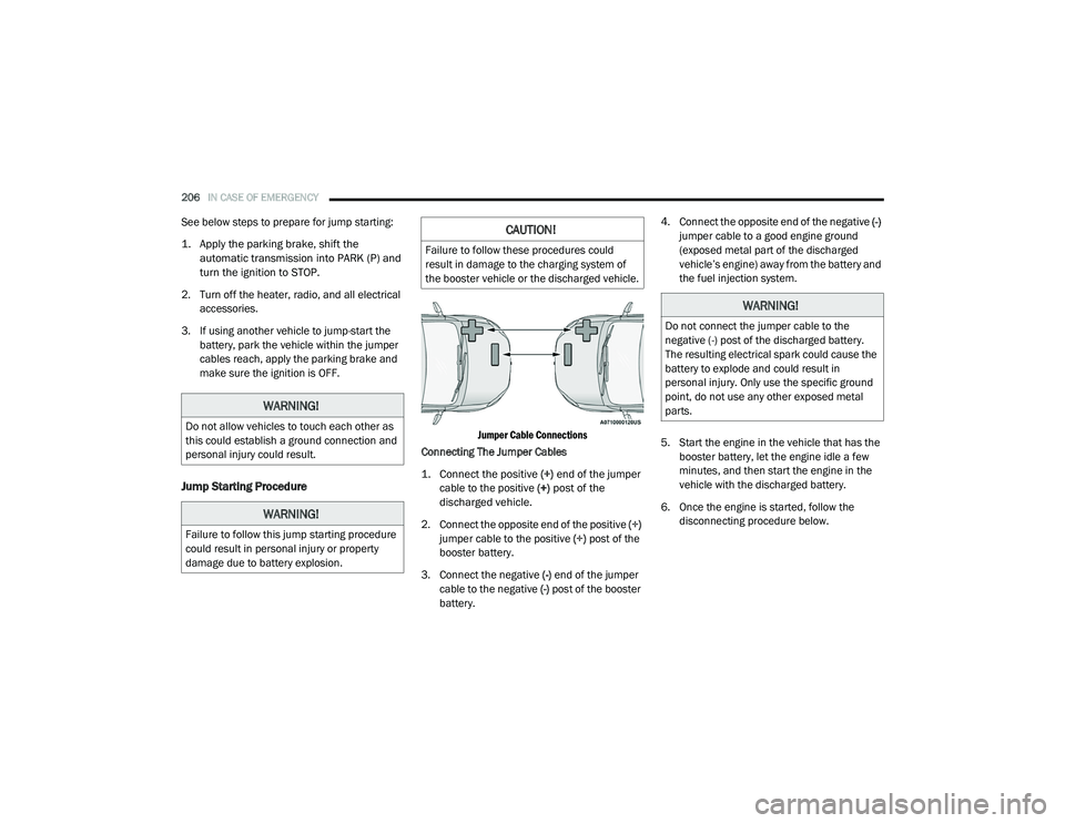
Jumper Cable Connections
Connecting The Jumper Cables
1. Connect the positive
(+) end of the jumper
cable to the positive (+)
post of the
discharged vehicle.
2. Connect the opposite end of the positive (+)
jumper cable to the positive (+) post of the
booster battery.
3. Connect the negative (-) end of the jumper
cable to the negative (-) post of the booster
battery. 4. Connect the opposite end of the negative
(-)
jumper cable to a good engine ground
(exposed metal part of the discharged
vehicle’s engine) away from the battery and
the fuel injection system.
5. Start the engine in the vehicle that has the booster battery, let the engine idle a few
minutes, and then start the engine in the
vehicle with the discharged battery.
6. Once the engine is started, follow the disconnecting procedure below.
WARNING!
Do not allow vehicles to touch each other as
this could establish a ground connection and
personal injury could result.
WARNING!
Failure to follow this jump starting procedure
could result in personal injury or property
damage due to battery explosion.
CAUTION!
Failure to follow these procedures could
result in damage to the charging system of
the booster vehicle or the discharged vehicle.
WARNING!
Do not connect the jumper cable to the
negative (-) post of the discharged battery.
The resulting electrical spark could cause the
battery to explode and could result in
personal injury. Only use the specific ground
point, do not use any other exposed metal
parts.
21_VM_OM_EN_USC_t.book Page 206
Page 209 of 280
IN CASE OF EMERGENCY207
Disconnecting The Jumper Cables
1. Disconnect the negative
(-)
end of the
jumper cable from the engine ground of
the vehicle with the discharged battery.
2. Disconnect the opposite end of the negative (-) jumper cable from the
negative (-) post of the booster battery.
3. Disconnect the positive (+) end of the
jumper cable from the positive (+) post of
the booster battery.
4. Disconnect the opposite end of the positive (+) jumper cable from the
positive (+) post of the vehicle with the
discharged battery.
If frequent jump starting is required to start your
vehicle you should have the battery and
charging system inspected at an authorized
dealer.
IF YOUR ENGINE OVERHEATS
If the vehicle is overheating, it will need to be
serviced by an authorized dealer.
In any of the following situations, you can
reduce the potential for overheating by taking
the appropriate action.
On the highways — slow down.
In city traffic — while stopped, place the trans -
mission in NEUTRAL (N), but do not increase
the engine idle speed while preventing
vehicle motion with the brakes. NOTE:
There are steps that you can take to slow down
an impending overheat condition:
If your Air Conditioner (A/C) is on, turn it off.
The A/C system adds heat to the engine
cooling system and turning the A/C off can
help remove this heat.
You can also turn the temperature control to
maximum heat, the mode control to floor and
the blower control to high. This allows the
heater core to act as a supplement to the
radiator and aids in removing heat from the
engine cooling system.
CAUTION!
Accessories plugged into the vehicle power
outlets draw power from the vehicle’s battery,
even when not in use (i.e., cellular devices,
etc.). Eventually, if plugged in long enough
without engine operation, the vehicle’s
battery will discharge sufficiently to degrade
battery life and/or prevent the engine from
starting.
WARNING!
You or others can be badly burned by hot
engine coolant (antifreeze) or steam from
your radiator. If you see or hear steam coming
from under the hood, do not open the hood
until the radiator has had time to cool. Never
try to open a cooling system pressure cap
when the radiator or coolant bottle is hot.7
21_VM_OM_EN_USC_t.book Page 207