inflation pressure RAM PROMASTER CITY 2021 Owners Manual
[x] Cancel search | Manufacturer: RAM, Model Year: 2021, Model line: PROMASTER CITY, Model: RAM PROMASTER CITY 2021Pages: 280, PDF Size: 15.78 MB
Page 5 of 280
3
INSTRUMENT CLUSTER DISPLAY ......................44 Location And Controls ................................. 45
Change Engine Oil — If Equipped................ 46
Instrument Cluster Display Menu Items..... 46
TRIP COMPUTER ...................................................47
Trip Button.................................................... 48
Trip Functions ............................................. 48
Values Displayed ......................................... 49
WARNING LIGHTS AND MESSAGES ..................49
Red Warning Lights...................................... 49
Yellow Warning Lights ................................. 52
Green Indicator Lights ................................. 55
Blue Indicator Lights .................................... 56
ONBOARD DIAGNOSTIC SYSTEM — OBD II .......56
Onboard Diagnostic System (OBD II)
Cybersecurity................................................ 56
EMISSIONS INSPECTION AND MAINTENANCE
PROGRAMS ...........................................................57
STARTING AND OPERATING
STARTING THE ENGINE .......................................58
Automatic Transmission .............................. 58
Normal Starting ............................................ 58
Cold Weather Operation ............................. 58
Extended Park Starting................................ 58
If Engine Fails To Start ................................ 59
After Starting ................................................ 59
ENGINE BLOCK HEATER — IF EQUIPPED ...........59
ENGINE BREAK-IN RECOMMENDATIONS .........60
PARKING BRAKE .................................................60 AUTOMATIC TRANSMISSION ............................. 62
Key Ignition Park Interlock .......................... 62
Brake/Transmission Shift Interlock (BTSI)
System ......................................................... 63 Nine-Speed Automatic Transmission ........ 63
POWER STEERING .............................................. 67
Power Steering Fluid Check ....................... 68
CRUISE CONTROL — IF EQUIPPED ..................... 68
To Activate.................................................... 69
To Set A Desired Speed............................... 69
To Vary The Speed Setting .......................... 69
To Accelerate For Passing ........................... 69
To Resume Speed ....................................... 70
To Deactivate .............................................. 70
PARKSENSE REAR PARK ASSIST —
IF EQUIPPED ......................................................... 70
ParkSense Rear Park Assist Sensors ......... 70
ParkSense Rear Park Assist Alerts ............. 71
ParkSense Rear Park Assist Failure
Indications.................................................... 72 Cleaning The ParkSense Rear Park Assist
System .......................................................... 72 ParkSense Rear Park Assist System Usage
Precautions .................................................. 72
PARKVIEW REAR BACK UP CAMERA ............... 73
REFUELING THE VEHICLE ................................... 74 VEHICLE LOADING ................................................75
Vehicle Certification Label .......................... 75
Gross Vehicle Weight Rating (GVWR) ......... 76
Gross Axle Weight Rating (GAWR) ............. 76
Tire Size ........................................................ 76
Rim Size ....................................................... 76
Inflation Pressure ........................................ 76
Curb Weight ................................................. 76
Overloading .................................................. 76
Loading......................................................... 76
TRAILER TOWING .................................................77
Common Towing Definitions ....................... 77
Trailer Hitch Classification .......................... 78
Trailer Towing Weights (Maximum Trailer
Weight Ratings) ........................................... 79 Trailer And Tongue Weight ......................... 79
Towing Requirements ................................ 79
Towing Tips ................................................. 82
RECREATIONAL TOWING (BEHIND
MOTORHOME) ......................................................83
Towing This Vehicle Behind Another
Vehicle .......................................................... 83 Recreational Towing — Automatic
Transmission................................................ 83
DRIVING TIPS ........................................................84
Driving On Slippery Surfaces ..................... 84
Driving Through Water ............................... 84
21_VM_OM_EN_USC_t.book Page 3
Page 55 of 280
GETTING TO KNOW YOUR INSTRUMENT PANEL53
Tire Pressure Monitoring System (TPMS)
Warning Light
The warning light switches on and a
message is displayed to indicate that
the tire pressure is lower than the
recommended value and/or that slow
pressure loss is occurring. In these cases,
optimal tire duration and fuel consumption may
not be guaranteed.
Should one or more tires be in the condition
mentioned above, the display will show the
indications corresponding to each tire.
Each tire, including the spare (if provided),
should be checked monthly when cold and
inflated to the inflation pressure recommended
by the vehicle manufacturer on the vehicle
placard or tire inflation pressure label. If your
vehicle has tires of a different size than the size indicated on the vehicle placard or tire inflation
pressure label, you should determine the
proper tire inflation pressure for those tires.
As an added safety feature, your vehicle has
been equipped with a TPMS that illuminates a
low tire pressure telltale when one or more of
your tires is significantly underinflated.
Accordingly, when the low tire pressure telltale
illuminates, you should stop and check your
tires as soon as possible, and inflate them to
the proper pressure. Driving on a significantly
underinflated tire causes the tire to overheat
and can lead to tire failure. Under-inflation also
reduces fuel efficiency and tire tread life, and
may affect the vehicle’s handling and stopping
ability.
Please note that the TPMS is not a substitute for
proper tire maintenance, and it is the driver’s
responsibility to maintain correct tire pressure,
even if under-inflation has not reached the level
to trigger illumination of the TPMS low tire
pressure telltale.
Your vehicle has also been equipped with a
TPMS malfunction indicator to indicate when
the system is not operating properly. The TPMS
malfunction indicator is combined with the low
tire pressure telltale. When the system detects
a malfunction, the telltale will flash for approximately one minute and then remain
continuously illuminated. This sequence will
continue upon subsequent vehicle start-ups as
long as the malfunction exists. When the
malfunction indicator is illuminated, the system
may not be able to detect or signal low tire
pressure as intended. TPMS malfunctions may
occur for a variety of reasons, including the
installation of replacement or alternate tires or
wheels on the vehicle that prevent the TPMS
from functioning properly. Always check the
TPMS malfunction telltale after replacing one or
more tires or wheels on your vehicle to ensure
that the replacement or alternate tires and
wheels allow the TPMS to continue to function
properly.
CAUTION!
Do not continue driving with one or more flat
tires as handling may be compromised. Stop
the vehicle, avoiding sharp braking and
steering. If a tire puncture occurs, repair
immediately using the dedicated tire repair
kit and contact an authorized dealer as soon
as possible.
3
21_VM_OM_EN_USC_t.book Page 53
Page 78 of 280
76STARTING AND OPERATING
Gross Vehicle Weight Rating (GVWR)
The GVWR is the total allowable weight of your
vehicle. This includes driver, passengers, and
cargo. The total load must be limited so that you
do not exceed the GVWR.
Gross Axle Weight Rating (GAWR)
The GAWR is the maximum capacity of the front
and rear axles. Distribute the load over the front
and rear axles evenly. Make sure that you do
not exceed either front or rear GAWR.
Tire Size
The tire size on the Vehicle Certification Label
represents the actual tire size on your vehicle.
Replacement tires must be equal to the load
capacity of this tire size.
Rim Size
This is the rim size that is appropriate for the tire
size listed.
Inflation Pressure
This is the cold tire inflation pressure for your
vehicle for all loading conditions up to full GAWR.
Curb Weight
The curb weight of a vehicle is defined as the
total weight of the vehicle with all fluids,
including vehicle fuel, at full capacity
conditions, and with no occupants or cargo
loaded into the vehicle. The front and rear curb
weight values are determined by weighing your
vehicle on a commercial scale before any
occupants or cargo are added.
Overloading
The load carrying components (axle, springs,
tires, wheels, etc.) of your vehicle will provide
satisfactory service as long as you do not
exceed the GVWR and the front and rear GAWR.
The best way to figure out the total weight of
your vehicle is to weigh it when it is fully loaded
and ready for operation. Weigh it on a
commercial scale to ensure that it is not over
the GVWR. Figure out the weight on the front and rear of
the vehicle separately. It is important that you
distribute the load evenly over the front and rear
axles.
Overloading can cause potential safety hazards
and shorten useful service life. Heavier axles or
suspension components do not necessarily
increase the vehicle's GVWR.
Loading
To load your vehicle properly, first figure out its
empty weight, axle-by-axle and side-by-side.
Store heavier items down low and be sure you
distribute their weight as evenly as possible.
Stow all loose items securely before driving. If
weighing the loaded vehicle shows that you
have exceeded either GAWR, but the total load
is within the specified GVWR, you must
redistribute the weight. Improper weight
distribution can have an adverse effect on the
way your vehicle steers and handles and the
way the brakes operate.
NOTE:
Refer to the “Vehicle Certification Label” affixed
to the B-Pillar or the rear of the driver's door for
your vehicle's GVWR and GAWRs.
WARNING!
Because the front wheels steer the vehicle, it
is important that you do not exceed the
maximum front or rear GAWR. A dangerous
driving condition can result if either rating is
exceeded. You could lose control of the
vehicle and have a collision.
21_VM_OM_EN_USC_t.book Page 76
Page 82 of 280
80STARTING AND OPERATING
(Continued)
Towing Requirements — Tires
Do not attempt to tow a trailer while using a
compact spare tire.
Do not drive more than 50 mph (80 km/h) when towing while using a full size spare tire.
Proper tire inflation pressures are essential
to the safe and satisfactory operation of your
vehicle.
Check the trailer tires for proper tire inflation
pressures before trailer usage.
Check for signs of tire wear or visible tire
damage before towing a trailer.
When replacing tires with a higher load
carrying capacity they will not increase the
vehicle's GVWR and GAWR limits.
For further information Ú page 234.
WARNING!
Make certain that the load is secured in the
trailer and will not shift during travel. When
trailering cargo that is not fully secured,
dynamic load shifts can occur that may be
difficult for the driver to control. You could
lose control of your vehicle and have a colli -
sion.
When hauling cargo or towing a trailer, do
not overload your vehicle or trailer. Over -
loading can cause a loss of control, poor
performance or damage to brakes, axle,
engine, transmission, steering, suspension,
chassis structure or tires.
Safety chains must always be used
between your vehicle and trailer. Always
connect the chains to the hook retainers of
the vehicle hitch. Cross the chains under
the trailer tongue and allow enough slack
for turning corners.
Vehicles with trailers should not be parked
on a grade. When parking, apply the
parking brake on the tow vehicle. Put the
tow vehicle transmission in PARK. For
four-wheel drive vehicles, make sure the
transfer case is not in NEUTRAL. Always,
block or "chock" the trailer wheels.
GCWR must not be exceeded.
Total weight must be distributed between
the tow vehicle and the trailer such that the
following four ratings are not exceeded :
GVWR
GTW
GAWR
Tongue weight rating for the trailer
hitch utilized.
WARNING! (Continued)
21_VM_OM_EN_USC_t.book Page 80
Page 151 of 280
SAFETY149
HSA will work in REVERSE and all forward gears
when the activation criteria have been met. The
system will not activate if the vehicle is placed
in NEUTRAL or PARK.
Traction Control System (TCS)
TCS monitors the amount of wheel spin of each
of the driven wheels. If wheel spin is detected,
brake pressure is applied to the slipping
wheel(s) and engine power is reduced to
provide enhanced acceleration and stability. A
feature of the TCS system, Brake Limited
Differential (BLD), functions similarly to a
limited slip differential and controls the wheel
spin across a driven axle. If one wheel on a
driven axle is spinning faster than the other, the
system will apply the brake of the spinning wheel. This will allow more engine torque to be
applied to the wheel that is not spinning. This
feature remains active even if TCS and ESC are
in the “Partial Off” mode Ú
page 146.
Trailer Sway Control (TSC) — If Equipped
TSC uses sensors in the vehicle to recognize an
excessively swaying trailer and will take the
appropriate actions to attempt to stop the sway.
The system may reduce engine power and apply
the brake of the appropriate wheel(s) to
counteract the sway of the trailer.
NOTE:
TSC cannot stop all trailers from swaying.
Always use caution when towing a trailer and
follow the trailer tongue weight recommenda -
tions Ú page 77.
When TSC is functioning, the ESC Activation/
Malfunction Indicator Light will flash, the engine
power may be reduced and you may feel the
brakes being applied to individual wheels to
attempt to stop the trailer from swaying. TSC is
disabled when the ESC system is in the “Partial
Off” mode.
AUXILIARY DRIVING SYSTEMS
Tire Pressure Monitoring System (TPMS)
The Tire Pressure Monitoring System (TPMS)
will warn the driver of a low tire pressure based
on the vehicle recommended cold placard
pressure.
The tire pressure will vary with temperature by
about 1 psi (7 kPa) for every 12°F (6.5°C). This
means that when the outside temperature
decreases, the tire pressure will decrease. Tire
pressure should always be set based on cold
inflation tire pressure. This is defined as the tire
pressure after the vehicle has not been driven
for at least three hours, or driven less than
1 mile (1.6 km) after a three hour period. The
cold tire inflation pressure must not exceed the
maximum inflation pressure molded into the
WARNING!
There may be situations on minor hills with a
loaded vehicle, or while pulling a trailer, when
the system will not activate and slight rolling
may occur. This could cause a collision with
another vehicle or object. Always remember
the driver is responsible for braking the
vehicle.
WARNING!
If TSC activates while driving, slow the vehicle
down, stop at the nearest safe location, and
adjust the trailer load to eliminate trailer
sway.
6
21_VM_OM_EN_USC_t.book Page 149
Page 153 of 280
SAFETY151
NOTE:
The TPMS is not intended to replace normal
tire care and maintenance or to provide
warning of a tire failure or condition.
The TPMS should not be used as a tire pres -
sure gauge while adjusting your tire pressure.
Driving on a significantly under-inflated tire
causes the tire to overheat and can lead to
tire failure. Under-inflation also reduces fuel
efficiency and tire tread life, and may affect
the vehicle’s handling and stopping ability.
The TPMS is not a substitute for proper tire
maintenance, and it is the driver’s responsi -
bility to maintain correct tire pressure using
an accurate tire pressure gauge, even if
under-inflation has not reached the level to
trigger illumination of the TPMS Warning
Light.
Seasonal temperature changes will affect
tire pressure, and the TPMS will monitor the
actual tire pressure in the tire Ú page 265.
Base System
This is the TPMS warning indicator
located in the instrument cluster.
The TPMS uses wireless technology with wheel
rim mounted electronic sensors to monitor tire
pressure levels. Sensors, mounted to each
wheel as part of the valve stem, transmit tire
pressure readings to the Receiver Module.
NOTE:
It is particularly important for you to check the
tire pressure in all of the tires on your vehicle
regularly and to maintain the proper pressure.
The TPMS consists of the following
components:
Receiver Module
Four Tire Pressure Monitoring sensors
Tire Pressure Monitoring System Warning
Light
Tire Pressure Monitoring Low Pressure
Warnings
The Tire Pressure Monitoring System Warning
Light will illuminate in the instrument cluster, an
audible chime will be activated, and the “Check
tire pressure” text message will display when
one or more of the four active road tire
pressures are low. Should this occur, you
should stop as soon as possible, check the
inflation pressure of each tire on your vehicle,
and inflate each tire to the vehicle’s
recommended cold placard pressure value. The
system will automatically update and the Tire
Pressure Monitoring Light will extinguish once
the updated tire pressures have been received.
The vehicle may need to be driven for up to
20 minutes above 15 mph (24 km/h) to receive
this information.
6
21_VM_OM_EN_USC_t.book Page 151
Page 154 of 280
152SAFETY
Check TPMS Warnings
The Tire Pressure Monitoring Warning Light will
flash on and off for 75 seconds and remain on
solid when a system fault is detected, an
audible chime will be activated and a proper
text message will be displayed. If the ignition
key is cycled, this sequence will repeat
providing the system fault still exists. The Tire
Pressure Monitoring Warning Light will turn off
when the fault condition no longer exists. A
system fault can occur with any of the following
scenarios:
1. Jamming due to electronic devices or
driving next to facilities emitting the same
radio frequencies as the TPM sensors.
2. Installing some form of aftermarket window tinting that affects radio wave signals.
3. Snow or ice around the wheels or wheel housings. 4. Using tire chains on the vehicle.
5. Using wheels/tires not equipped with TPM
sensors.
NOTE:
Your vehicle can be equipped with either a Tire
Service Kit, a compact spare tire or a regular
size spare tire (with or without original TPMS
sensor).
1. Tire Service Kit (original tire sealant – if equipped): After fixing the punctured tire
with original tire sealant, the original
situation will be restored, so system will
turn off the telltale during the normal drive.
2. Compact Spare Tire – if equipped: The compact spare wheel is not equipped with a
TPMS sensor. So when mounted, during the
normal drive the system will turn on the
telltale (flashing for approximately
75 seconds then remains solid). This
condition persists until a wheel equipped
with original TPMS sensor has been
mounted on the vehicle. 3. Regular size spare tire (not equipped with
TPMS sensor): When mounted, during the
normal drive the system will turn on the
telltale (flashing for approximately
75 seconds then remains solid). This
condition persists until a wheel equipped
with original TPMS sensor has been
mounted on the vehicle. Then the system
will be restored and the telltale will turn off
during the normal drive.
4. Regular size spare tire (equipped with TPMS sensor): When mounted, the telltale will
turn off during the normal drive.
5. In all the above cases, please check the replacement tire inflation pressure before
driving your vehicle.
6. In case of tire replacement, if the vehicle is driven for short periods of time, then the
system can take a while to be restored.
NOTE:
For a correct Tire Pressure Monitoring behavior,
please wait for about 20 minutes in key-off
during each tire substitution.
21_VM_OM_EN_USC_t.book Page 152
Page 189 of 280
SAFETY187
Periodic Safety Checks You Should Make
Outside The Vehicle
Tires
Examine tires for excessive tread wear and
uneven wear patterns. Check for stones, nails,
glass, or other objects lodged in the tread or
sidewall. Inspect the tread for cuts and cracks.
Inspect sidewalls for cuts, cracks, and bulges.
Check the lug nut/bold torque for tightness.
Check the tires (including spare) for proper cold
inflation pressure.
Lights
Have someone observe the operation of brake
lights and exterior lights while you work the
controls. Check turn signal and high beam
indicator lights on the instrument panel.
Door Latches
Check for proper closing, latching, and locking.
Fluid Leaks
Check area under the vehicle after overnight
parking for fuel, coolant, oil, or other fluid leaks.
Also, if gasoline fumes are detected or if fuel or
brake fluid leaks are suspected, the cause
should be located and corrected immediately.
NEVER place any objects under the floor
mat (e.g., towels, keys, etc.). These objects
could change the position of the floor mat
and may cause interference with the accel -
erator, brake, or clutch pedals.
If the vehicle carpet has been removed and
re-installed, always properly attach carpet
to the floor and check the floor mat
fasteners are secure to the vehicle carpet.
Fully depress each pedal to check for inter -
ference with the accelerator, brake, or
clutch pedals then re-install the floor mats.
It is recommended to only use mild soap
and water to clean your floor mats. After
cleaning, always check your floor mat has
been properly installed and is secured to
your vehicle using the floor mat fasteners
by lightly pulling mat.
WARNING! (Continued)
6
21_VM_OM_EN_USC_t.book Page 187
Page 205 of 280
IN CASE OF EMERGENCY203
(Continued)
Insert the power plug into the vehicle power
outlet socket. Start the vehicle engine.
Push the Tire Service Kit power button on. The
electric compressor will be turned on, sealant
and air will inflate the tire.
Minimum 26 psi (1.8 bar) of pressure should be
reached within 20 minutes. If the pressure has
not been reached, turn off and remove the Tire
Service Kit, drive the vehicle 30 feet
(10 meters) back and forth, to better distribute
the sealant inside the tire.
Attach the clear flexible filling tube of the
compressor directly to the tire valve and repeat
the inflation process.
When the correct pressure has been reached,
start driving the vehicle to uniformly distribute
the sealant inside the tire. After 10 minutes,
stop and check the tire pressure. If the pressure
is below 19 psi (1.3 bar), do not drive the
vehicle, as the tire is too damaged, contact the
nearest authorized dealer.WARNING!
Do not attempt to seal a tire on the side of
the vehicle closest to traffic. Pull far enough
off the road to avoid the danger of being hit
when using the Tire Service Kit.
Do not use Tire Service Kit or drive the
vehicle under the following circumstances:
If the puncture in the tire tread is
approximately 1/4 inch (6 mm) or
larger.
If the tire has any sidewall damage.
If the tire has any damage from driving
with extremely low tire pressure.
If the tire has any damage from driving
on a flat tire.
If the wheel has any damage.
If you are unsure of the condition of the
tire or the wheel.
Keep Tire Service Kit away from open
flames or heat source.
A loose Tire Service Kit thrown forward in a
collision or hard stop could endanger the
occupants of the vehicle. Always stow the
Tire Service Kit in the place provided.
Failure to follow these warnings can result
in injuries that are serious or fatal to you,
your passengers, and others around you.
Take care not to allow the contents of Tire
Service Kit to come in contact with hair,
eyes, or clothing. Tire Service Kit sealant is
harmful if inhaled, swallowed, or absorbed
through the skin. It causes skin, eye, and
respiratory irritation. Flush immediately
with plenty of water if there is any contact
with eyes or skin. Change clothing as soon
as possible, if there is any contact with
clothing.
Tire Service Kit Sealant solution contains
latex. In case of an allergic reaction or rash,
consult a physician immediately. Keep Tire
Service Kit out of reach of children. If swal -
lowed, rinse mouth immediately with plenty
of water and drink plenty of water. Do not
induce vomiting! Consult a physician imme -
diately.
WARNING! (Continued)
7
21_VM_OM_EN_USC_t.book Page 203
Page 206 of 280
204IN CASE OF EMERGENCY
If the pressure is at 19 psi (1.3 bar) or above
repeat the inflation process to reach the correct
tire pressure and continue driving.
Peel off the warning label from the bottle and
place it on the dashboard as a reminder to the
driver that a tire has been treated with Tire
Service Kit. NOTE:
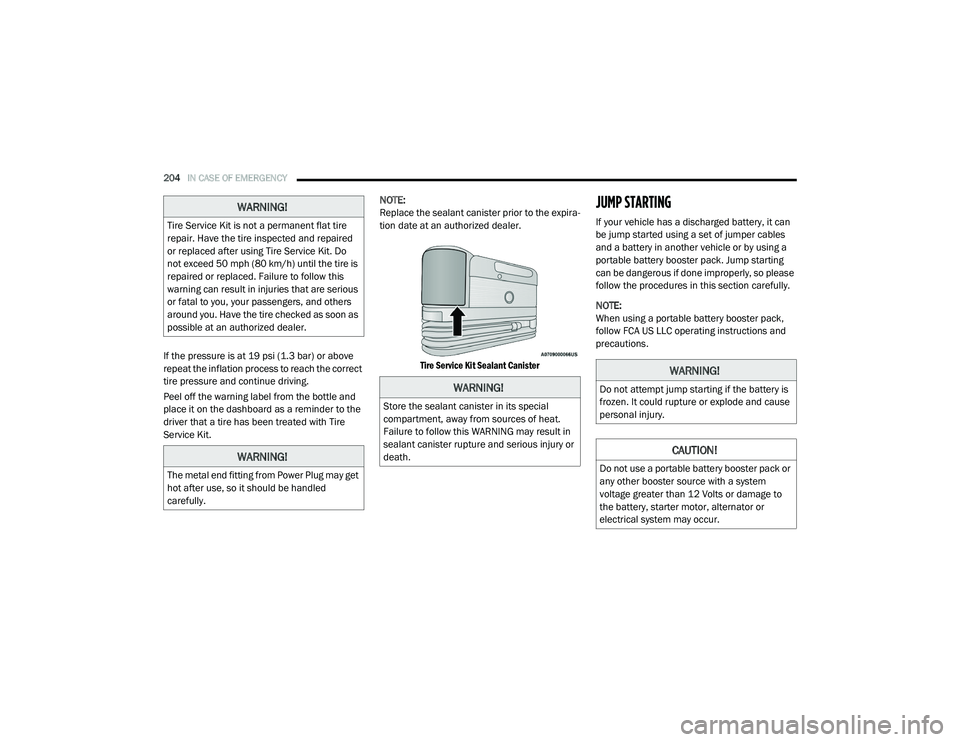
Replace the sealant canister prior to the expira-
tion date at an authorized dealer.
Tire Service Kit Sealant Canister
JUMP STARTING
If your vehicle has a discharged battery, it can
be jump started using a set of jumper cables
and a battery in another vehicle or by using a
portable battery booster pack. Jump starting
can be dangerous if done improperly, so please
follow the procedures in this section carefully.
NOTE:
When using a portable battery booster pack,
follow FCA US LLC operating instructions and
precautions.
WARNING!
Tire Service Kit is not a permanent flat tire
repair. Have the tire inspected and repaired
or replaced after using Tire Service Kit. Do
not exceed 50 mph (80 km/h) until the tire is
repaired or replaced. Failure to follow this
warning can result in injuries that are serious
or fatal to you, your passengers, and others
around you. Have the tire checked as soon as
possible at an authorized dealer.
WARNING!
The metal end fitting from Power Plug may get
hot after use, so it should be handled
carefully.
WARNING!
Store the sealant canister in its special
compartment, away from sources of heat.
Failure to follow this WARNING may result in
sealant canister rupture and serious injury or
death.
WARNING!
Do not attempt jump starting if the battery is
frozen. It could rupture or explode and cause
personal injury.
CAUTION!
Do not use a portable battery booster pack or
any other booster source with a system
voltage greater than 12 Volts or damage to
the battery, starter motor, alternator or
electrical system may occur.
21_VM_OM_EN_USC_t.book Page 204