lock RAM PROMASTER CITY 2022 User Guide
[x] Cancel search | Manufacturer: RAM, Model Year: 2022, Model line: PROMASTER CITY, Model: RAM PROMASTER CITY 2022Pages: 260, PDF Size: 8.45 MB
Page 18 of 260
16GETTING TO KNOW YOUR VEHICLE
NOTE:For emergency exit from the rear seats when the
Child-Protection Door Lock system is engaged,
manually raise the door lock knob to the unlocked
position, roll down the window, and open the door
using the outside door handle.
STEERING WHEEL
TILT/TELESCOPING STEERING COLUMN
This feature allows you to tilt the steering column
upward or downward. It also allows you to lengthen
or shorten the steering column. The steering
column control is located on the steering column,
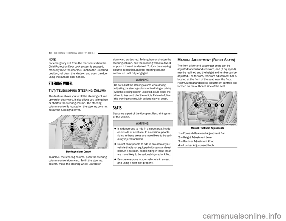
below the turn signal lever.
Steering Column Control
To unlock the steering column, push the steering
column control downward. To tilt the steering
column, move the steering wheel upward or downward as desired. To lengthen or shorten the
steering column, pull the steering wheel outward
or push it inward as desired. To lock the steering
column in position, pull the steering column
control up until fully engaged.
SEATS
Seats are a part of the Occupant Restraint system
of the vehicle.
MANUAL ADJUSTMENT (FRONT SEATS)
The front driver and passenger seats can be
adjusted forward and rearward, and (if equipped),
may be reclined and the height and lumbar can be
adjusted. The forward/rearward adjustment bar is
located at the front of the seat, near the floor.
Height, lumbar and recline adjustment controls are
located on the outboard side of the seat.
Manual Front Seat Adjustments
WARNING!
Do not adjust the steering column while driving.
Adjusting the steering column while driving or driving
with the steering column unlocked, could cause the
driver to lose control of the vehicle. Failure to follow
this warning may result in serious injury or death.
WARNING!
It is dangerous to ride in a cargo area, inside
or outside of a vehicle. In a collision, people
riding in these areas are more likely to be seri -
ously injured or killed.
Do not allow people to ride in any area of your
vehicle that is not equipped with seats and seat
belts. In a collision, people riding in these areas
are more likely to be seriously injured or killed.
Be sure everyone in your vehicle is in a seat
and using a seat belt properly.
1 — Forward/Rearward Adjustment Bar
2 — Height Adjustment Lever
3 — Recliner Adjustment Knob
4 — Lumbar Adjustment Knob
22_VM_OM_EN_USC_t.book Page 16
Page 24 of 260
22GETTING TO KNOW YOUR VEHICLE
MIRRORS
INSIDE REARVIEW MIRROR
Manual Mirror — If Equipped
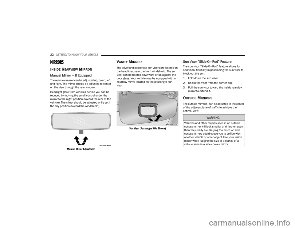
The rearview mirror can be adjusted up, down, left,
and right. The mirror should be adjusted to center
on the view through the rear window.
Headlight glare from vehicles behind you can be
reduced by moving the small control under the
mirror to the night position (toward the rear of the
vehicle). The mirror should be adjusted while set in
the day position (toward the windshield).
Manual Mirror Adjustment
VANITY MIRROR
The driver and passenger sun visors are located on
the headliner, near the front windshield. The sun
visor can be rotated downward or up against the
door glass. Your vehicle may be equipped with a
courtesy mirror located on the passenger sun
visor.
Sun Visor (Passenger Side Shown)
Sun Visor “Slide-On-Rod” Feature
The sun visor “Slide-On-Rod” feature allows for
additional flexibility in positioning the sun visor to
block out the sun.
1. Fold down the sun visor.
2. Unclip the visor from the corner clip.
3. Pull the sun visor toward the inside rearview mirror to extend it.
OUTSIDE MIRRORS
The outside mirror(s) can be adjusted to the center
of the adjacent lane of traffic to achieve the
optimal view.
WARNING!
Vehicles and other objects seen in an outside
convex mirror will look smaller and farther away
than they really are. Relying too much on side
convex mirrors could cause you to collide with
another vehicle or other object. Use your inside
mirror when judging the size or distance of a
vehicle seen in a side convex mirror.
22_VM_OM_EN_USC_t.book Page 22
Page 26 of 260
24GETTING TO KNOW YOUR VEHICLE
EXTERIOR LIGHTS
MULTIFUNCTION LEVER
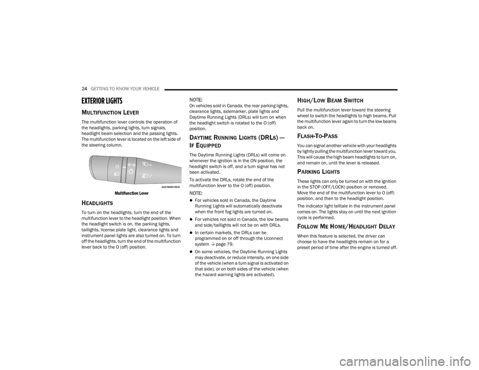
The multifunction lever controls the operation of
the headlights, parking lights, turn signals,
headlight beam selection and the passing lights.
The multifunction lever is located on the left side of
the steering column.
Multifunction Lever
HEADLIGHTS
To turn on the headlights, turn the end of the
multifunction lever to the headlight position. When
the headlight switch is on, the parking lights,
taillights, license plate light, clearance lights and
instrument panel lights are also turned on. To turn
off the headlights, turn the end of the multifunction
lever back to the O (off) position.
NOTE:On vehicles sold in Canada, the rear parking lights,
clearance lights, sidemarker, plate lights and
Daytime Running Lights (DRLs) will turn on when
the headlight switch is rotated to the O (off)
position.
DAYTIME RUNNING LIGHTS (DRLS) —
I
F EQUIPPED
The Daytime Running Lights (DRLs) will come on
whenever the ignition is in the ON position, the
headlight switch is off, and a turn signal has not
been activated.
To activate the DRLs, rotate the end of the
multifunction lever to the O (off) position.
NOTE:
For vehicles sold in Canada, the Daytime
Running Lights will automatically deactivate
when the front fog lights are turned on.
For vehicles not sold in Canada, the low beams
and side/taillights will not be on with DRLs.
In certain markets, the DRLs can be
programmed on or off through the Uconnect
system Ú page 79.
On some vehicles, the Daytime Running Lights
may deactivate, or reduce intensity, on one side
of the vehicle (when a turn signal is activated on
that side), or on both sides of the vehicle (when
the hazard warning lights are activated).
HIGH/LOW BEAM SWITCH
Pull the multifunction lever toward the steering
wheel to switch the headlights to high beams. Pull
the multifunction lever again to turn the low beams
back on.
FLASH-TO-PASS
You can signal another vehicle with your headlights
by lightly pulling the multifunction lever toward you.
This will cause the high beam headlights to turn on,
and remain on, until the lever is released.
PARKING LIGHTS
These lights can only be turned on with the ignition
in the STOP (OFF/LOCK) position or removed.
Move the end of the multifunction lever to O (off)
position, and then to the headlight position.
The indicator light telltale in the instrument panel
comes on. The lights stay on until the next ignition
cycle is performed.
FOLLOW ME HOME/HEADLIGHT DELAY
When this feature is selected, the driver can
choose to have the headlights remain on for a
preset period of time after the engine is turned off.
22_VM_OM_EN_USC_t.book Page 24
Page 27 of 260
GETTING TO KNOW YOUR VEHICLE25
Activation
Remove the key or turn the ignition to the STOP
(OFF/LOCK) position, and pull the multifunction
lever toward the steering wheel within two
minutes. Each time the lever is pulled, the
activation of the lights will be extended by 30
seconds. The activation of the lights can be
extended to a maximum of 210 seconds.
Deactivation
Pull the multifunction lever toward the steering
wheel and hold it for more than two seconds.
FOG LIGHTS — IF EQUIPPED
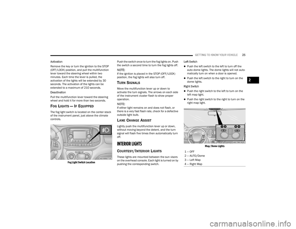
The fog light switch is located on the center stack
of the instrument panel, just above the climate
controls.
Fog Light Switch Location
Push the switch once to turn the fog lights on. Push
the switch a second time to turn the fog lights off.
NOTE:If the ignition is placed in the STOP (OFF/LOCK)
position, the fog lights will also turn off.
TURN SIGNALS
Move the multifunction lever up or down to
activate the turn signals. The arrows on each side
of the instrument cluster flash to show proper
operation.
NOTE:If either light remains on and does not flash, or
there is a very fast flash rate, check for a defective
outside light bulb.
LANE CHANGE ASSIST
Lightly push the multifunction lever up or down,
without moving beyond the detent, and the turn
signal will flash five times then automatically turn
off.
INTERIOR LIGHTS
COURTESY/INTERIOR LIGHTS
These lights are mounted between the sun visors
on the overhead console. Each light is turned on by
pushing the corresponding switch. Left Switch
Push the left switch to the left to turn off the
auto dome lights. The dome lights will not auto -
matically turn on when a door is opened.
Push the left switch to the right to turn on the
dome lights.
Right Switch
Push the right switch to the left to turn on the
left map light.
Push the right switch to the right to turn on the
right map light.
Map/Dome Lights
1 — OFF
2 — AUTO/Dome
3 — Left Map
4 — Right Map
2
22_VM_OM_EN_USC_t.book Page 25
Page 31 of 260
GETTING TO KNOW YOUR VEHICLE29
(Continued)
Recirculation Button
Press and release this button to change
the system between recirculation mode
and outside air mode. The Recirculation
indicator and the A/C indicator
illuminate when the Recirculation button is
pressed. Recirculation can be used when outside
conditions such as smoke, odors, dust, or high
humidity are present. Recirculation can be used in
all modes. Recirculation may be unavailable
(button on the touchscreen greyed out) if
conditions exist that could create fogging on the
inside of the windshield. The A/C can be
deselected manually without disturbing the mode
control selection. Continuous use of the
Recirculation mode may make the inside air stuffy
and window fogging may occur. Extended use of
this mode is not recommended. Recirculation
mode may automatically adjust to optimize
customer experience for warming, cooling,
dehumidification, etc.
In cold weather, use of Recirculation mode may
lead to excessive window fogging. The
Recirculation feature may be unavailable if
conditions exist that could create fogging on the
inside of the windshield.
Front Defrost Setting
Use Defrost mode with maximum
temperature settings for best
windshield and side window defrosting
and defogging. Turn the knob to the
Front Defrost position. Air comes from the
windshield and side window demist outlets.
Rear Defrost Button — If Equipped
Push and release the Rear Defrost
Control button to turn on the rear
window defroster and the heated
outside mirrors (if equipped). An
indicator will illuminate when the rear window
defroster is on. The rear window defroster
automatically turns OFF after 20 minutes.Temperature Control
Temperature Control regulates the temperature of
the air forced through the climate system.
The temperature increases as you turn
the temperature control knob clockwise.
The temperature decreases as you turn
the temperature control knob
counterclockwise.
Blower Control
There are four blower speeds. Use this
control to regulate the amount of air
forced through the system in any mode
you select. The blower speed increases
as you move the control clockwise from the OFF
position.
CAUTION!
Failure to follow these cautions can cause
damage to the heating elements:
Use care when washing the inside of the rear
window. Do not use abrasive window cleaners
on the interior surface of the window. Use a
soft cloth and a mild washing solution, wiping
parallel to the heating elements. Labels can
be peeled off after soaking with warm water.
Do not use scrapers, sharp instruments, or
abrasive window cleaners on the interior
surface of the window.
Keep all objects a safe distance from the
window.
CAUTION!
2
22_VM_OM_EN_USC_t.book Page 29
Page 33 of 260
GETTING TO KNOW YOUR VEHICLE31
Cabin Air Filter
The Climate Control system filters out dust and
pollen from the air. Contact an authorized dealer to
service your cabin air filter, and to have it replaced
when needed.
Operating Tips Chart
INTERIOR STORAGE AND EQUIPMENT
STORAGE
Glove Compartment
The glove compartment is located on the
passenger side of the instrument panel.
To open the glove compartment, pull the release
handle.
NOTE:The glove compartment handle is equipped with a
lock. To lock the glove compartment, insert the
mechanical key into the glove compartment
handle lock cylinder and turn the key to the lock
position and remove the key. Use the reverse
sequence to unlock the glove compartment.
Glove Compartment
Dash Storage
The dash storage is located on the right side of the
instrument panel above the glove compartment.
Dash Storage
WEATHER CONTROL SETTINGS
Hot Weather And
Vehicle Interior Is Very Hot Set the mode control to
(Panel Mode),
(A/C) on, and blower
on high. Roll down the windows for a minute
to flush out the hot air. Adjust the controls as needed to achieve comfort.
Warm Weather Turn (A/C) on and
set the mode control to
(Panel Mode).
Cool Sunny Operate in
(Bi-Level Mode).
Cool & Humid Conditions Set the mode control to
(Mix Mode) and
turn on (A/C) to
keep windows clear.
Cold Weather Set the mode control to
(Floor Mode). If
windshield fogging
starts to occur, move
the control to (Mix Mode).
WEATHER CONTROL SETTINGS
2
22_VM_OM_EN_USC_t.book Page 31
Page 36 of 260
34GETTING TO KNOW YOUR VEHICLE
WINDOWS
POWER WINDOW CONTROLS —
I
F EQUIPPED
The window switches on the driver’s door control
all door windows.
Power Window Switches
The passenger door windows can also be operated
by using the single window switch on the
passenger door trim panel. If the vehicle is
equipped with rear power windows, a single
opening and closing switch on the rear passenger
doors for passenger window control is provided.
NOTE:
The key off power delay feature will allow the
power windows to operate for up to three
minutes after the ignition is turned off. This
feature is canceled when either front door is
opened.
The power window switches remain active for up
to three minutes after the ignition switch has
been turned off. Opening either of the vehicle’s
front doors will cancel this feature.
Automatic Window Features
Auto-Down Feature
The driver and passenger door power window
switches have an Auto-Down feature. Push the
window switch down for a short period of time, then
release, and the window will go down automatically.
To stop the window from going all the way down
during the Auto-Down operation, pull up or push
down on the switch briefly.
Auto-Up Feature With Anti-Pinch Protection
Lift the window switch up for a short period of time
and release; the window will go up automatically.
To stop the window from going all the way up
during the Auto-Up operation, push down on the
switch briefly.
To close the window part way, lift the window
switch briefly and release it when you want the
window to stop.
If the window runs into any obstacle during
auto-closure, it will reverse direction and then go
back down. Remove the obstacle and use the
window switch again to close the window.
1 — Front Window Control Switches
2 — Rear Window Lock Switch (If Equipped)
3 — Rear Window Control Switches (If Equipped)
WARNING!
Never leave children alone in a vehicle, or with
access to an unlocked vehicle. Allowing chil
-
dren to be in a vehicle unattended is
dangerous for a number of reasons. A child or
others could be seriously or fatally injured.
Children should be warned not to touch the
parking brake, brake pedal or the gear
selector.
Do not leave the key fob in or near the vehicle
or in a location accessible to children. A child
could operate power windows, other controls,
or move the vehicle.
WARNING!
There is no anti-pinch protection when the window
is almost closed. To avoid personal injury be sure
to clear your arms, hands, fingers and all objects
from the window path before closing.
22_VM_OM_EN_USC_t.book Page 34
Page 37 of 260
GETTING TO KNOW YOUR VEHICLE35
Power Windows System Initialization
The power windows may be reset if any of the
following occurs:
On the front doors:
Fuse or battery are disconnected when the
window is moving
50 window movements without ever closing
the window
On the rear doors (in addition to the conditions
for the front doors):
Fuse or battery are disconnected when the
window is moving
The auto-reverse system is activated while
the window is moving and the door is
opening
50 window movements without ever closing
the window
One door opening with the window moving,
without ever closing the door
Three doors opening with the window in
motion. During these maneuvers, the upper
stop position is never reached Proceed as follows for initialization:
1. Completely close the driver's door window,
keeping the window switch pushed for at
least five seconds after the (upper) end of
travel position.
2. Proceed in the same way on the passenger's window switches.
Rear Window Lockout Switch — If Equipped
The window lockout switch on the driver's door trim
panel allows you to disable the window controls on
the rear passenger doors. To disable the window
controls, push and release the window lockout
button (the indicator light on the button will turn
on). To enable the window controls, push and
release the window lockout button again (the
indicator light on the button will turn off).
WINDOW BAR GRATES — IF EQUIPPED
This vehicle may be equipped with metal grates
over the sliding door windows. This feature is a part
of the vehicle’s safety system, and is designed to
protect you and your passengers in the event of an
accident.
Window Bar Grates
WIND BUFFETING
Wind buffeting can be described as the perception
of pressure on the ears or a helicopter-type sound
in the ears. Your vehicle may exhibit wind buffeting
with the windows down in certain open or partially
open positions. This is a normal occurrence and
can be minimized. If wind buffeting occurs, open
the front windows together to minimize the
buffeting.
WARNING!
The metal grates over the sliding door windows
are designed to protect you in the event of an
accident. Modification or removal of the grates
could lead to serious injury or death.
2
22_VM_OM_EN_USC_t.book Page 35
Page 38 of 260
36GETTING TO KNOW YOUR VEHICLE
HOOD
OPENING
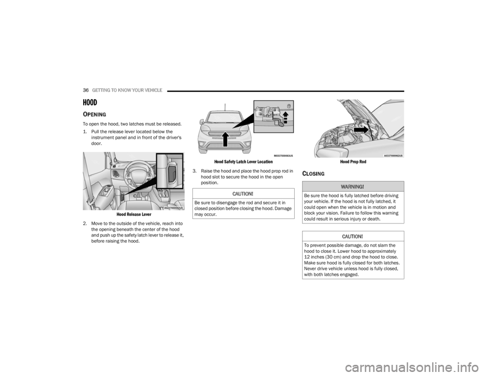
To open the hood, two latches must be released.
1. Pull the release lever located below the
instrument panel and in front of the driver's
door.
Hood Release Lever
2. Move to the outside of the vehicle, reach into the opening beneath the center of the hood
and push up the safety latch lever to release it,
before raising the hood.
Hood Safety Latch Lever Location
3. Raise the hood and place the hood prop rod in hood slot to secure the hood in the open
position.
Hood Prop Rod
CLOSING
CAUTION!
Be sure to disengage the rod and secure it in
closed position before closing the hood. Damage
may occur.
WARNING!
Be sure the hood is fully latched before driving
your vehicle. If the hood is not fully latched, it
could open when the vehicle is in motion and
block your vision. Failure to follow this warning
could result in serious injury or death.
CAUTION!
To prevent possible damage, do not slam the
hood to close it. Lower hood to approximately
12 inches (30 cm) and drop the hood to close.
Make sure hood is fully closed for both latches.
Never drive vehicle unless hood is fully closed,
with both latches engaged.
22_VM_OM_EN_USC_t.book Page 36
Page 40 of 260
38GETTING TO KNOW YOUR VEHICLE
(Continued)
To move the crossbars, loosen the attachments,
located at the upper edge of each crossbar,
approximately eight turns using the anti-theft
wrench provided with the Mopar® crossbars.
Then, move the crossbar to the desired position,
keeping the crossbars parallel to the rack frame.
Once the crossbar is in the desired position,
re-tighten it with the wrench to lock the crossbar
into position.
NOTE:
To help control wind noise when the crossbars
are not in use, place the front and rear cross
-
bars approximately 24 inches (61 cm) apart.
Optimal noise reduction can then be achieved
by adjusting the front crossbar forward or aft
using increments of 1 inch (2.5 cm).
If the crossbar (or any metallic object) is placed
over the satellite radio antenna (if equipped),
you may experience interruption of satellite
radio reception. For improved satellite radio
reception, avoid placing the rear crossbar over
the satellite radio antenna.
WARNING!
Cargo must be securely tied down before driving
your vehicle. Improperly secured loads can fly off
the vehicle, particularly at high speeds, resulting
in personal injury or property damage. Follow
the roof rack cautions when carrying cargo on
your roof rack.
CAUTION!
To prevent damage to the roof of your vehicle,
DO NOT carry any loads on the roof rack
without the crossbars deployed. The load
should be secured and placed on top of the
crossbars, not directly on the roof. If it is
necessary to place the load on the roof, place
a blanket or other protective layer between
the load and the roof surface.
To avoid damage to the roof rack and vehicle,
do not exceed the maximum roof rack load
capacity of 150 lb (68 kg). Always distribute
heavy loads as evenly as possible and secure
the load appropriately.
Loads should always be secured to crossbars
first, with tie down loops used as additional
securing points if needed. Tie loops are
intended as supplementary tie down points
only. Do not use ratcheting mechanisms with
the tie loops. Check the straps and thumb
wheels frequently to be sure that the load
remains securely attached.
Long loads that extend over the windshield,
such as wood panels or surfboards, or loads
with large frontal area should be secured to
both the front and rear of the vehicle.
Travel at reduced speeds and turn corners
carefully when carrying large or heavy loads
on the roof rack. Wind forces, due to natural
causes or nearby truck traffic, can add sudden
upward lift to a load. This is especially true on
large flat loads and may result in damage to
the cargo or your vehicle.
CAUTION!
22_VM_OM_EN_USC_t.book Page 38