driver seat adjustment RAM PROMASTER CITY 2022 Owners Manual
[x] Cancel search | Manufacturer: RAM, Model Year: 2022, Model line: PROMASTER CITY, Model: RAM PROMASTER CITY 2022Pages: 260, PDF Size: 8.45 MB
Page 18 of 260

16GETTING TO KNOW YOUR VEHICLE
NOTE:For emergency exit from the rear seats when the
Child-Protection Door Lock system is engaged,
manually raise the door lock knob to the unlocked
position, roll down the window, and open the door
using the outside door handle.
STEERING WHEEL
TILT/TELESCOPING STEERING COLUMN
This feature allows you to tilt the steering column
upward or downward. It also allows you to lengthen
or shorten the steering column. The steering
column control is located on the steering column,
below the turn signal lever.
Steering Column Control
To unlock the steering column, push the steering
column control downward. To tilt the steering
column, move the steering wheel upward or downward as desired. To lengthen or shorten the
steering column, pull the steering wheel outward
or push it inward as desired. To lock the steering
column in position, pull the steering column
control up until fully engaged.
SEATS
Seats are a part of the Occupant Restraint system
of the vehicle.
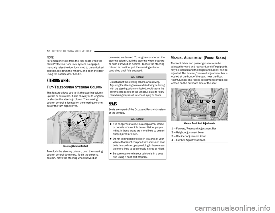
MANUAL ADJUSTMENT (FRONT SEATS)
The front driver and passenger seats can be
adjusted forward and rearward, and (if equipped),
may be reclined and the height and lumbar can be
adjusted. The forward/rearward adjustment bar is
located at the front of the seat, near the floor.
Height, lumbar and recline adjustment controls are
located on the outboard side of the seat.
Manual Front Seat Adjustments
WARNING!
Do not adjust the steering column while driving.
Adjusting the steering column while driving or driving
with the steering column unlocked, could cause the
driver to lose control of the vehicle. Failure to follow
this warning may result in serious injury or death.
WARNING!
It is dangerous to ride in a cargo area, inside
or outside of a vehicle. In a collision, people
riding in these areas are more likely to be seri -
ously injured or killed.
Do not allow people to ride in any area of your
vehicle that is not equipped with seats and seat
belts. In a collision, people riding in these areas
are more likely to be seriously injured or killed.
Be sure everyone in your vehicle is in a seat
and using a seat belt properly.
1 — Forward/Rearward Adjustment Bar
2 — Height Adjustment Lever
3 — Recliner Adjustment Knob
4 — Lumbar Adjustment Knob
22_VM_OM_EN_USC_t.book Page 16
Page 21 of 260

GETTING TO KNOW YOUR VEHICLE19
HEAD RESTRAINTS
Head restraints are designed to reduce the risk of
injury by restricting head movement in the event of
a rear impact. Head restraints should be adjusted
so that the top of the head restraint is located
above the top of your ear.
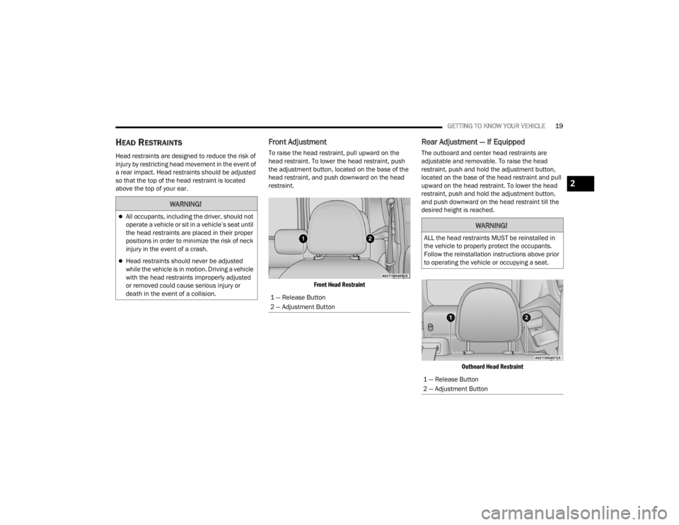
Front Adjustment
To raise the head restraint, pull upward on the
head restraint. To lower the head restraint, push
the adjustment button, located on the base of the
head restraint, and push downward on the head
restraint.
Front Head Restraint
Rear Adjustment — If Equipped
The outboard and center head restraints are
adjustable and removable. To raise the head
restraint, push and hold the adjustment button,
located on the base of the head restraint and pull
upward on the head restraint. To lower the head
restraint, push and hold the adjustment button,
and push downward on the head restraint till the
desired height is reached.
Outboard Head Restraint
WARNING!
All occupants, including the driver, should not
operate a vehicle or sit in a vehicle’s seat until
the head restraints are placed in their proper
positions in order to minimize the risk of neck
injury in the event of a crash.
Head restraints should never be adjusted
while the vehicle is in motion. Driving a vehicle
with the head restraints improperly adjusted
or removed could cause serious injury or
death in the event of a collision.
1 — Release Button
2 — Adjustment Button
WARNING!
ALL the head restraints MUST be reinstalled in
the vehicle to properly protect the occupants.
Follow the reinstallation instructions above prior
to operating the vehicle or occupying a seat.
1 — Release Button
2 — Adjustment Button
2
22_VM_OM_EN_USC_t.book Page 19
Page 44 of 260

42GETTING TO KNOW YOUR INSTRUMENT PANEL
NOTE:If the indicator message illuminates when you start
the vehicle, the oil change indicator system did not
reset. If necessary, repeat this procedure.
INSTRUMENT CLUSTER DISPLAY MENU
I
TEMS
Speed Beep
This function is used to set a speed limit (MPH or
km/h); the driver is alerted when this limit is
exceeded.
To set the desired speed limit:
1. Push the
MENU
button briefly. The display will
show the wording (SPEED BEEP) and the unit
(MPH) or (km/h) previously set.
2. If the function is on, push and release the up
or down arrow button to select the required
speed limit and then push MENU to confirm.
NOTE:The speed may be set in the range from 20 to
125 mph (30 to 200 km/h) according to the previ -
ously chosen unit.
The setting will increase/decrease by five units
each time the up or down arrow button is
pushed. Hold down the up or down arrow
button to automatically increase/decrease the setting rapidly. Complete the adjustment when you
approach the desired value.
Push the
MENU button briefly to return to the menu
screen or hold the MENU button down to return to
the standard screen without storing.
To cancel the setting:
1. Briefly push the
MENU
button, “ON” will flash
in the display.
2. Push the down arrow button, “OFF” will
flash in the display.
3. Push the MENU button briefly to return to the
menu screen or hold the MENU button down to
return to the standard screen without storing.
Trip B Data
This function can be used to activate (On) or
deactivate (Off) the Trip B display (Partial Trip)
Ú page 43.
To switch the function On/Off:
1. Push the
MENU
button briefly. The display will
flash On or Off according to the previous
setting.
2. Push and release the up or down arrow
button to select. Push the
MENU button briefly to return to the menu
screen or hold the MENU button down to return to
the standard screen without storing.
Buzzer Volume
With this function, the volume of the acoustic
signal which accompanies the display of failure/
warning can be adjusted according to seven levels.
To set the desired volume:
1. Push the
MENU
button, the previously set
volume level will flash on the display.
2. Push and release the up or down arrow
button to adjust.
3. Push the MENU button to return to the menu
screen or hold the MENU button down to
return to the standard screen without storing.
Seat Belt Buzzer
Only shows in the instrument cluster display if the
seat belt reminder was previously deactivated by
an authorized dealer.
NOTE:This is a one-time occurrence to enable the
acoustic signal.
22_VM_OM_EN_USC_t.book Page 42