instrument cluster RAM PROMASTER CITY 2022 Owners Manual
[x] Cancel search | Manufacturer: RAM, Model Year: 2022, Model line: PROMASTER CITY, Model: RAM PROMASTER CITY 2022Pages: 260, PDF Size: 8.45 MB
Page 4 of 260
2
INTRODUCTION
SYMBOLS KEY ...........................................................7
VAN CONVERSIONS/CAMPERS ..............................7
VEHICLE MODIFICATIONS/ALTERATIONS .............7
SYMBOL GLOSSARY.................................................8
GETTING TO KNOW YOUR VEHICLE
KEYS ....................................................................... 10 Key Fob .............................................................10
SENTRY KEY ........................................................... 12
IGNITION SWITCH .................................................. 12
DOORS ................................................................... 13
Power Door Locks ............................................13
Auto Unlock Doors ............................................13
Sliding Side Door ..............................................13
Double Rear Swing Doors ................................15
Child-Protection Door Lock System.................15
STEERING WHEEL.................................................. 16
Tilt/Telescoping Steering Column ...................16
SEATS ...................................................................... 16
Manual Adjustment (Front Seats) ...................16
Folding Rear Seat — If Equipped .....................17
Heated Seats — If Equipped ............................18
Head Restraints ...............................................19 UCONNECT VOICE RECOGNITION ........................21
Introducing Voice Recognition.........................21
Basic Voice Commands ...................................21
Get Started .......................................................21
Additional Information .....................................21
MIRRORS ...............................................................22
Inside Rearview Mirror .....................................22
Vanity Mirror .....................................................22
Outside Mirrors ................................................22
EXTERIOR LIGHTS ..................................................24
Multifunction Lever ..........................................24
Headlights ........................................................24
Daytime Running Lights (DRLs) —
If Equipped .......................................................24
High/Low Beam Switch....................................24
Flash-To-Pass ..................................................24
Parking Lights ..................................................24
Follow Me Home/Headlight Delay ..................24
Fog Lights — If Equipped .................................25
Turn Signals ......................................................25
Lane Change Assist..........................................25
INTERIOR LIGHTS ..................................................25
Courtesy/Interior Lights ...................................25
WIPERS AND WASHERS ......................................26
Front Wiper Operation......................................27
Rear Wiper And Washer —If Equipped ............28 CLIMATE CONTROLS ............................................ 28
Manual Climate Control Descriptions And
Functions .......................................................... 28
Operating Tips .................................................. 30
INTERIOR STORAGE AND EQUIPMENT ............... 31
Storage ............................................................. 31
USB Control — If Equipped .............................. 32
Power Outlets .................................................. 32
WINDOWS ............................................................. 34
Power Window Controls —If Equipped ........... 34
Window Bar Grates — If Equipped .................. 35
Wind Buffeting .................................................35
HOOD....................................................................... 36
Opening............................................................. 36
Closing ..............................................................36
CARGO AREA FEATURES ...................................... 37
Rear Cargo Tie-Downs ..................................... 37
ROOF RACK — IF EQUIPPED................................. 37
GETTING TO KNOW YOUR
INSTRUMENT PANEL
INSTRUMENT CLUSTER......................................... 39
Instrument Cluster Descriptions ..................... 40
INSTRUMENT CLUSTER DISPLAY ....................... 40
Location And Controls...................................... 40
Change Engine Oil — If Equipped ................... 41
Instrument Cluster Display Menu Items ......... 42
22_VM_OM_EN_USC_t.book Page 2
Page 27 of 260
GETTING TO KNOW YOUR VEHICLE25
Activation
Remove the key or turn the ignition to the STOP
(OFF/LOCK) position, and pull the multifunction
lever toward the steering wheel within two
minutes. Each time the lever is pulled, the
activation of the lights will be extended by 30
seconds. The activation of the lights can be
extended to a maximum of 210 seconds.
Deactivation
Pull the multifunction lever toward the steering
wheel and hold it for more than two seconds.
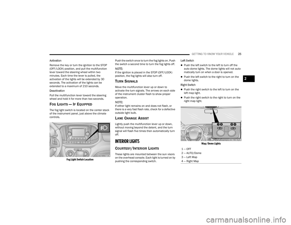
FOG LIGHTS — IF EQUIPPED
The fog light switch is located on the center stack
of the instrument panel, just above the climate
controls.
Fog Light Switch Location
Push the switch once to turn the fog lights on. Push
the switch a second time to turn the fog lights off.
NOTE:If the ignition is placed in the STOP (OFF/LOCK)
position, the fog lights will also turn off.
TURN SIGNALS
Move the multifunction lever up or down to
activate the turn signals. The arrows on each side
of the instrument cluster flash to show proper
operation.
NOTE:If either light remains on and does not flash, or
there is a very fast flash rate, check for a defective
outside light bulb.
LANE CHANGE ASSIST
Lightly push the multifunction lever up or down,
without moving beyond the detent, and the turn
signal will flash five times then automatically turn
off.
INTERIOR LIGHTS
COURTESY/INTERIOR LIGHTS
These lights are mounted between the sun visors
on the overhead console. Each light is turned on by
pushing the corresponding switch. Left Switch
Push the left switch to the left to turn off the
auto dome lights. The dome lights will not auto -
matically turn on when a door is opened.
Push the left switch to the right to turn on the
dome lights.
Right Switch
Push the right switch to the left to turn on the
left map light.
Push the right switch to the right to turn on the
right map light.
Map/Dome Lights
1 — OFF
2 — AUTO/Dome
3 — Left Map
4 — Right Map
2
22_VM_OM_EN_USC_t.book Page 25
Page 41 of 260
39
GETTING TO KNOW YOUR INSTRUMENT PANEL
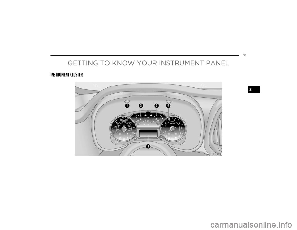
INSTRUMENT CLUSTER
3
22_VM_OM_EN_USC_t.book Page 39
Page 42 of 260
40GETTING TO KNOW YOUR INSTRUMENT PANEL
INSTRUMENT CLUSTER DESCRIPTIONS
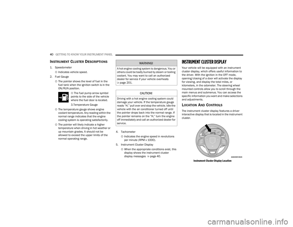
1. Speedometer
Indicates vehicle speed.
2. Fuel Gauge
The pointer shows the level of fuel in the
fuel tank when the ignition switch is in the
ON/RUN position.
The fuel pump arrow symbol
points to the side of the vehicle
where the fuel door is located.
3.Temperature Gauge
The temperature gauge shows engine
coolant temperature. Any reading within the
normal range indicates that the engine
cooling system is operating satisfactorily.
The pointer will likely indicate a higher
temperature when driving in hot weather or
up mountain grades. It should not be
allowed to exceed the upper limits of the
normal operating range. 4. Tachometer
Indicates the engine speed in revolutions
per minute (RPM x 1000).
5. Instrument Cluster Display
When the appropriate conditions exist, this
display shows the instrument cluster
display messages Ú page 40.
INSTRUMENT CLUSTER DISPLAY
Your vehicle will be equipped with an instrument
cluster display, which offers useful information to
the driver. With the ignition in the OFF mode,
opening/closing of a door will activate the display
for viewing, and display the total miles, or
kilometers, in the odometer. The steering wheel
mounted controls allow you to scroll through the
main menus and submenus. You can access the
specific information you want and make selections
and adjustments.
LOCATION AND CONTROLS
The instrument cluster display features a driver
interactive display that is located in the instrument
cluster.
Instrument Cluster Display Location
WARNING!
A hot engine cooling system is dangerous. You or
others could be badly burned by steam or boiling
coolant. You may want to call an authorized
dealer for service if your vehicle overheats
Úpage 201.
CAUTION!
Driving with a hot engine cooling system could
damage your vehicle. If the temperature gauge
reads “H,” pull over and stop the vehicle. Idle the
vehicle with the air conditioner turned off until
the pointer drops back into the normal range. If
the pointer remains on the “H,” turn the engine
off immediately and call an authorized dealer for
service.
22_VM_OM_EN_USC_t.book Page 40
Page 43 of 260
GETTING TO KNOW YOUR INSTRUMENT PANEL41
The menu items described below are an example
of what can be found in the vehicle's menu:
Dimmer
Speed Beep
Trip A / B (options are selectable through the
steering wheel stalk)
Buzzer Volume
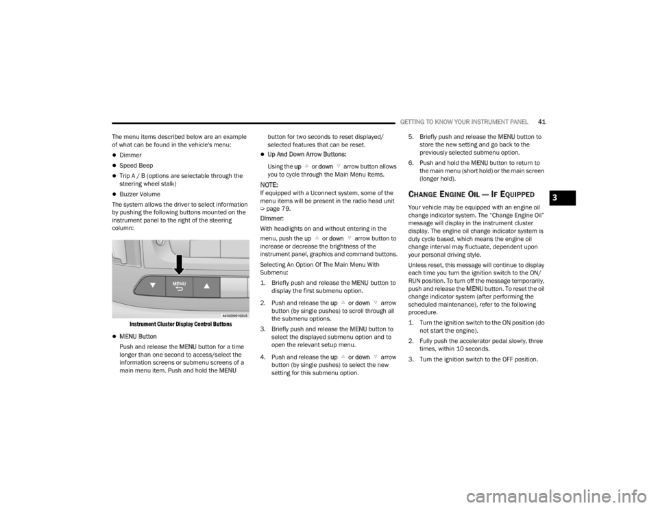
The system allows the driver to select information
by pushing the following buttons mounted on the
instrument panel to the right of the steering
column:
Instrument Cluster Display Control Buttons
MENU Button
Push and release the MENU button for a time
longer than one second to access/select the
information screens or submenu screens of a
main menu item. Push and hold the MENU button for two seconds to reset displayed/
selected features that can be reset.
Up And Down Arrow Buttons:
Using the up or down arrow button allows
you to cycle through the Main Menu Items.
NOTE:If equipped with a Uconnect system, some of the
menu items will be present in the radio head unit
Ú page 79.
Dimmer:
With headlights on and without entering in the
menu, push the up or down arrow button to
increase or decrease the brightness of the
instrument panel, graphics and command buttons.
Selecting An Option Of The Main Menu With
Submenu:
1. Briefly push and release the
MENU
button to
display the first submenu option.
2. Push and release the up or down arrow
button (by single pushes) to scroll through all
the submenu options.
3. Briefly push and release the MENU button to
select the displayed submenu option and to
open the relevant setup menu.
4. Push and release the up or down arrow
button (by single pushes) to select the new
setting for this submenu option. 5. Briefly push and release the MENU
button to
store the new setting and go back to the
previously selected submenu option.
6. Push and hold the MENU button to return to
the main menu (short hold) or the main screen
(longer hold).CHANGE ENGINE OIL — IF EQUIPPED
Your vehicle may be equipped with an engine oil
change indicator system. The “Change Engine Oil”
message will display in the instrument cluster
display. The engine oil change indicator system is
duty cycle based, which means the engine oil
change interval may fluctuate, dependent upon
your personal driving style.
Unless reset, this message will continue to display
each time you turn the ignition switch to the ON/
RUN position. To turn off the message temporarily,
push and release the MENU button. To reset the oil
change indicator system (after performing the
scheduled maintenance), refer to the following
procedure.
1. Turn the ignition switch to the ON position (do not start the engine).
2. Fully push the accelerator pedal slowly, three times, within 10 seconds.
3. Turn the ignition switch to the OFF position.
3
22_VM_OM_EN_USC_t.book Page 41
Page 44 of 260
42GETTING TO KNOW YOUR INSTRUMENT PANEL
NOTE:If the indicator message illuminates when you start
the vehicle, the oil change indicator system did not
reset. If necessary, repeat this procedure.
INSTRUMENT CLUSTER DISPLAY MENU
I
TEMS
Speed Beep
This function is used to set a speed limit (MPH or
km/h); the driver is alerted when this limit is
exceeded.
To set the desired speed limit:
1. Push the
MENU
button briefly. The display will
show the wording (SPEED BEEP) and the unit
(MPH) or (km/h) previously set.
2. If the function is on, push and release the up
or down arrow button to select the required
speed limit and then push MENU to confirm.
NOTE:The speed may be set in the range from 20 to
125 mph (30 to 200 km/h) according to the previ -
ously chosen unit.
The setting will increase/decrease by five units
each time the up or down arrow button is
pushed. Hold down the up or down arrow
button to automatically increase/decrease the setting rapidly. Complete the adjustment when you
approach the desired value.
Push the
MENU button briefly to return to the menu
screen or hold the MENU button down to return to
the standard screen without storing.
To cancel the setting:
1. Briefly push the
MENU
button, “ON” will flash
in the display.
2. Push the down arrow button, “OFF” will
flash in the display.
3. Push the MENU button briefly to return to the
menu screen or hold the MENU button down to
return to the standard screen without storing.
Trip B Data
This function can be used to activate (On) or
deactivate (Off) the Trip B display (Partial Trip)
Ú page 43.
To switch the function On/Off:
1. Push the
MENU
button briefly. The display will
flash On or Off according to the previous
setting.
2. Push and release the up or down arrow
button to select. Push the
MENU button briefly to return to the menu
screen or hold the MENU button down to return to
the standard screen without storing.
Buzzer Volume
With this function, the volume of the acoustic
signal which accompanies the display of failure/
warning can be adjusted according to seven levels.
To set the desired volume:
1. Push the
MENU
button, the previously set
volume level will flash on the display.
2. Push and release the up or down arrow
button to adjust.
3. Push the MENU button to return to the menu
screen or hold the MENU button down to
return to the standard screen without storing.
Seat Belt Buzzer
Only shows in the instrument cluster display if the
seat belt reminder was previously deactivated by
an authorized dealer.
NOTE:This is a one-time occurrence to enable the
acoustic signal.
22_VM_OM_EN_USC_t.book Page 42
Page 45 of 260
GETTING TO KNOW YOUR INSTRUMENT PANEL43
Exit Menu
This is the last function that closes the cycle of
settings listed in the menu screen.
1. Pushing the
MENU
button briefly will return
the display to the standard screen without
storing.
2. Push the down arrow button to return to the
first menu item on the display.
TRIP COMPUTER
The Trip Computer is located in the instrument
cluster. It features a driver interactive display
(displays information such as trip information,
range, fuel consumption, average speed, and
travel time).
NOTE:The Uconnect System also has a Trip Computer
display and menus to customize the information
displayed in the cluster Ú page 79.
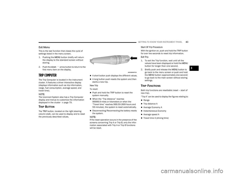
TRIP BUTTON
The TRIP button, located on the right steering
column stalk, can be used to display and to reset
the previously described values.
A short button push displays the different values.
A long button push resets the system and then
starts a new trip.
New Trip
To reset:
Push and hold the TRIP button to reset the
system manually.
When the “Trip distance” reaches
99999.9 miles or kilometers or when the
“Travel time” reaches 999.59 (999 hours and
59 minutes), the system is reset automatically.
Disconnecting/Reconnecting the battery resets
the system.
NOTE:If the reset operation occurs in the presence of the
screens concerning Trip A or Trip B, only the infor -
mation associated with Trip A or Trip B functions
will be reset. Start Of Trip Procedure
With the ignition on, push and hold the TRIP button
for over two seconds to reset trip information.
Exit Trip
1. To exit the Trip function, wait until all the
values have been displayed or hold the
MENU
button for longer than one second.
2. Briefly push and release the MENU button to
go back to the menu screen or push and hold
the MENU button (approximately one second)
to go back to the main screen without storing
settings.
TRIP FUNCTIONS
Both trip functions are resettable (reset — start of
new trip).
“Trip A” can be used to display the figures relating to:
Range
Trip distance A
Average Economy A
Instantaneous Economy
Average speed A
Travel time A (driving time)
3
22_VM_OM_EN_USC_t.book Page 43
Page 49 of 260

GETTING TO KNOW YOUR INSTRUMENT PANEL47
Transmission Fault Warning Light
This light will illuminate (together with a
message in the instrument cluster
display and a buzzer) to indicate a
transmission fault. Contact an
authorized dealer if the message remains after
restarting the engine.
Engine Oil Level Warning Light
This warning light appears on the panel
when the engine oil level falls below the
minimum recommended value. Restore
the correct engine oil level or contact an
authorized dealer for service.
YELLOW WARNING LIGHTS
Anti-Lock Brake System (ABS) Warning
Light
This light monitors the ABS. The light will
turn on when the ignition is placed in the
ON/RUN or MAR/ON/RUN position and
may stay on for as long as four seconds.
If the ABS light remains on or turns on while
driving, then the Anti-Lock portion of the brake
system is not functioning and service is required.
However, the conventional brake system will
continue to operate normally if the brake warning
light is not on. If the ABS light is on, the brake system should be
serviced as soon as possible to restore the
benefits of Anti-Lock Brakes. If the ABS light does
not turn on when the ignition is placed in the ON/
RUN or MAR/ON/RUN position, have the light
inspected by an authorized dealer.
Low Fuel Warning Light
When the fuel level reaches
approximately 2–3 gal (9–11 L) this
light will turn on, and remain on until
fuel is added.
Generic Warning Light
The Generic Warning Light will
illuminate if any of the following
conditions occur: Engine Oil Pressure
Sensor Failure, External Light Failure,
Parking Sensor Failure, Fuel Cut-Off Fail/
Intervention, Generic Failure on Trailer, or Air Bag
telltale recovery.
The telltale will blink in case of an Air Bag Warning
Light Failure. Contact an authorized dealer
immediately for service.
Tire Pressure Monitoring System (TPMS)
Warning Light
The warning light switches on and a
message is displayed to indicate that
the tire pressure is lower than the
recommended value and/or that slow
pressure loss is occurring. In these cases, optimal
tire duration and fuel consumption may not be
guaranteed.
Should one or more tires be in the condition
mentioned above, the display will show the
indications corresponding to each tire.
Each tire, including the spare (if provided), should be
checked monthly when cold and inflated to the
inflation pressure recommended by the vehicle
manufacturer on the vehicle placard or tire inflation
pressure label. If your vehicle has tires of a different
size than the size indicated on the vehicle placard or
tire inflation pressure label, you should determine the
proper tire inflation pressure for those tires.
CAUTION!
Do not continue driving with one or more flat
tires as handling may be compromised. Stop the
vehicle, avoiding sharp braking and steering. If a
tire puncture occurs, repair immediately using
the dedicated tire repair kit and contact an
authorized dealer as soon as possible.
3
22_VM_OM_EN_USC_t.book Page 47
Page 51 of 260
GETTING TO KNOW YOUR INSTRUMENT PANEL49
Electronic Stability Control (ESC) Warning
Light — If Equipped
The ESC Indicator Light in the
instrument cluster will come on when
the ignition is placed in the ON/RUN or
MAR/ON/RUN position, and when ESC
is activated. It should go out with the engine
running. If the ESC Indicator Light comes on continuously with the engine running, a
malfunction has been detected in the ESC system.
If this light remains on after several ignition cycles,
and the vehicle has been driven several miles
(kilometers) at speeds greater than 30 mph
(48 km/h), see an authorized dealer as soon as
possible to have the problem diagnosed and
corrected.
The ESC OFF Indicator Light and the ESC Indi
-
cator Light come on momentarily each time the
ignition is placed in the ON/RUN or MAR/ON/
RUN position.
Each time the ignition is turned to ON/RUN or
MAR/ON/RUN, the ESC system will be on, even
if it was turned off previously.
The ESC system will make buzzing or clicking
sounds when it is active. This is normal; the
sounds will stop when ESC becomes inactive.
This light will come on when the vehicle is in an
ESC event.
Electronic Stability Control (ESC) OFF
Warning Light — If Equipped
This warning light indicates the ESC is off.
Each time the ignition is turned to
ON/RUN or ACC/ON/RUN, the ESC
system will be on, even if it was turned
off previously.
GREEN INDICATOR LIGHTS
Turn Signal Indicator Lights
When the left or right turn signal is
activated, the turn signal indicator will
flash independently and the
corresponding exterior turn signal lamps
will flash. Turn signals can be activated when the
multifunction lever is moved down (left) or up
(right).
NOTE:
A continuous chime will sound if the vehicle is
driven more than 1 mile (1.6 km) with either
turn signal on.
Check for an inoperative outside light bulb if
either indicator flashes at a rapid rate.
Parking/Headlights On Indicator Light
This indicator light will illuminate when
the parking lights or headlights are
turned on Ú page 24.
Front Fog Indicator Light — If Equipped
This indicator light will illuminate when
the front fog lights are on Ú page 24.
WARNING!
A malfunctioning catalytic converter, as
referenced above, can reach higher
temperatures than in normal operating
conditions. This can cause a fire if you drive
slowly or park over flammable substances such
as dry plants, wood, cardboard, etc. This could
result in death or serious injury to the driver,
occupants or others.
CAUTION!
Prolonged driving with the Malfunction Indicator
Light (MIL) on could cause damage to the
vehicle control system. It also could affect fuel
economy and driveability. If the MIL is flashing,
severe catalytic converter damage and power
loss will soon occur. Immediate service is
required.
3
22_VM_OM_EN_USC_t.book Page 49
Page 52 of 260
50GETTING TO KNOW YOUR INSTRUMENT PANEL
Cruise Control Indicator Light —
If Equipped
This indicator light will illuminate when
the cruise control is activated
Úpage 60.
NOTE:There will be no change in the indicator light when
the desired speed is set.
BLUE INDICATOR LIGHTS
High Beam Indicator Light
This indicator light will illuminate to
indicate that the high beam headlights
are on. With the low beams activated,
push the multifunction lever forward
(toward the front of the vehicle) to turn on the high
beams. Pull the multifunction lever rearward
(toward the rear of the vehicle) to turn off the high
beams. If the high beams are off, pull the lever
toward you for a temporary high beam on, “flash to
pass” scenario.
WHITE INDICATOR LIGHTS
Speed Warning Indicator Light —
If Equipped
When Set Speed Warning is turned on,
the speed warning telltale will illuminate
in the instrument cluster with a number
matching the set speed. When the set
speed is exceeded, a single chime will sound along
with pop-up message of speed warning exceeded.
Speed Warning can be turned on and off in the
instrument cluster display Ú page 40.
NOTE:The number “55” is only an example of a speed
that can be set.
ONBOARD DIAGNOSTIC SYSTEM — OBD II
Your vehicle is equipped with a sophisticated
Onboard Diagnostic system called OBD II. This
system monitors the performance of the
emissions, engine, and transmission control
systems. When these systems are operating
properly, your vehicle will provide excellent
performance and fuel economy, as well as engine
emissions well within current government
regulations. If any of these systems require service, the OBD II
system will turn on the Malfunction Indicator Light
(MIL). It will also store diagnostic codes and other
information to assist your service technician in
making repairs. Although your vehicle will usually
be drivable and not need towing, see an authorized
dealer for service as soon as possible.
CAUTION!
Prolonged driving with the MIL on could cause
further damage to the emission control
system. It could also affect fuel economy and
driveability. The vehicle must be serviced
before any emissions tests can be performed.
If the MIL is flashing while the vehicle is
running, severe catalytic converter damage
and power loss will soon occur. Immediate
service is required.
22_VM_OM_EN_USC_t.book Page 50