spare wheel RAM PROMASTER CITY 2022 Owners Manual
[x] Cancel search | Manufacturer: RAM, Model Year: 2022, Model line: PROMASTER CITY, Model: RAM PROMASTER CITY 2022Pages: 260, PDF Size: 8.45 MB
Page 6 of 260
4
MULTIMEDIA
UCONNECT SYSTEMS ........................................... 78
CYBERSECURITY ................................................... 78
UCONNECT SETTINGS .......................................... 79 Uconnect 3/3 NAV Settings .............................79
UCONNECT INTRODUCTION.................................. 88
Identifying Your Radio ......................................88
Safety And General Information ......................90
UCONNECT MODES ............................................... 91
Radio Mode ......................................................91
Media Mode......................................................98
Phone Mode ................................................. 100
NAVIGATION MODE — IF EQUIPPED ..................110
Operating Navigation Mode —If Equipped ... 110
STEERING WHEEL AUDIO CONTROLS —
IF EQUIPPED ........................................................ 128
Radio Operation ............................................ 128
Media Mode................................................... 129
RAM TELEMATICS - IF EQUIPPED ...................... 129
Ram Telematics General Information .......... 129
RADIO OPERATION AND MOBILE PHONES ..... 130
Regulatory And Safety Information .............. 130
SAFETY
SAFETY FEATURES .............................................. 131Four-Wheel Anti-Lock Brake System (ABS).. 131
Electronic Brake Control (EBC) System ...... 132
AUXILIARY DRIVING SYSTEMS.......................... 135
Tire Pressure Monitoring System (TPMS) .... 135
OCCUPANT RESTRAINT SYSTEMS ................... 137
Occupant Restraint Systems ........................ 137
Important Safety Precautions ...................... 137Seat Belt Systems ........................................ 138Supplemental Restraint Systems (SRS) ...... 144Child Restraints ............................................. 152
SAFETY TIPS ....................................................... 168
Transporting Passengers .............................. 168Transporting Pets ......................................... 168
Safety Checks You Should Make Inside
The Vehicle ................................................... 168
Periodic Safety Checks You Should Make
Outside The Vehicle ...................................... 169
Exhaust Gas................................................... 170
Carbon Monoxide Warnings ........................ 170
IN CASE OF EMERGENCY
HAZARD WARNING FLASHERS......................... 171
JACKING AND TIRE CHANGING ......................... 171
Preparations For Jacking ............................. 171
Jack Location — If Equipped ......................... 172
Removing The Spare Tire —If Equipped....... 172 Jacking Instructions ...................................... 174
Vehicles With Alloy Wheels ........................... 177
Vehicles Equipped With Wheel Covers ........ 178
TIRE SERVICE KIT — IF EQUIPPED .................... 179
Tire Service Kit Storage ................................ 179Tire Service Kit Usage ................................... 179
JUMP STARTING .................................................. 181
Preparations For Jump Starting ................... 181Jump Starting Procedure .............................. 182
IF YOUR ENGINE OVERHEATS ........................... 183
IGNITION KEY REMOVAL OVERRIDE ................. 184
GEAR SELECTOR OVERRIDE .............................. 184
FREEING A STUCK VEHICLE .............................. 185
TOWING A DISABLED VEHICLE .......................... 187
ENHANCED ACCIDENT RESPONSE SYSTEM
(EARS) .................................................................. 188
EVENT DATA RECORDER (EDR) ......................... 188
SERVICING AND MAINTENANCE
SCHEDULED SERVICING .................................... 189
Maintenance Plan ......................................... 190
ENGINE COMPARTMENT .................................... 193
Engine Compartment — 2.4L ....................... 193
Checking Oil Level ........................................ 194
Adding Washer Fluid .................................... 194
Maintenance-Free Battery ........................... 194
Pressure Washing ......................................... 195
22_VM_OM_EN_USC_t.book Page 4
Page 7 of 260
5
VEHICLE MAINTENANCE ..................................... 195 Engine Oil ....................................................... 195
Engine Oil Filter ............................................. 196
Engine Air Cleaner Filter .............................. 196Air Conditioner Maintenance ....................... 196
Body Lubrication............................................ 197
Windshield Wiper Blades .............................. 197Exhaust System ............................................ 198
Cooling System ............................................. 199
Brake System ............................................... 202
Automatic Transmission .............................. 203Upfitter Connectors — If Equipped ............... 204
Fuses.............................................................. 207
Bulb Replacement ......................................... 213
TIRES ..................................................................... 217
Tire Safety Information ................................ 217
Tires — General Information ........................ 225
Tire Types ....................................................... 228
Spare Tires — If Equipped ............................. 229
Wheel And Wheel Trim Care ........................ 231
Tire Chains and Traction Devices ................ 232
Tire Rotation Recommendations ................. 232
DEPARTMENT OF TRANSPORTATION UNIFORM
TIRE QUALITY GRADES ...................................... 232
Treadwear ...................................................... 232Traction Grades ............................................. 233
Temperature Grades ..................................... 233
STORING THE VEHICLE ...................................... 233 BODYWORK ......................................................... 233
Protection From Atmospheric Agents .......... 233
Body And Underbody Maintenance.............. 234Preserving The Bodywork ............................. 234
INTERIORS .......................................................... 235
Seats And Fabric Parts ................................. 235
Plastic And Coated Parts .............................. 235Leather Surfaces ........................................... 235Glass Surfaces ............................................. 235
TECHNICAL SPECIFICATIONS
VEHICLE IDENTIFICATION NUMBER (VIN) ........ 236
BRAKE SYSTEM ................................................... 236
WHEEL AND TIRE TORQUE SPECIFICATIONS .. 236
Torque Specifications ................................... 236
FUEL REQUIREMENTS ........................................ 237
2.4L Engine ................................................... 237
Reformulated Gasoline ................................ 238Gasoline/Oxygenate Blends ........................ 238
E-85 Usage In Non-Flex Fuel Vehicles ......... 238CNG And LP Fuel System Modifications ...... 238MMT In Gasoline ........................................... 238Materials Added To Fuel ............................... 239
Fuel System Cautions ................................... 239
FLUID CAPACITIES ............................................. 240
ENGINE FLUIDS AND LUBRICANTS................... 240
CHASSIS FLUIDS AND LUBRICANTS ................ 241
CUSTOMER ASSISTANCE
SUGGESTIONS FOR OBTAINING SERVICE FOR
YOUR VEHICLE .................................................... 242
Prepare For The Appointment ...................... 242
Prepare A List ................................................ 242
Be Reasonable With Requests..................... 242
IF YOU NEED ASSISTANCE ................................ 242
FCA US LLC Customer Center....................... 242
FCA Canada Inc. Customer Center .............. 242
Mexico............................................................ 243
Puerto Rico And US Virgin Islands ............... 243
Customer Assistance For The Hearing
Or Speech Impaired (TDD/TTY) .................... 243
Service Contract ........................................... 243
WARRANTY INFORMATION ................................ 244
MOPAR® PARTS ................................................. 244
REPORTING SAFETY DEFECTS .......................... 244
In The 50 United States And
Washington, D.C............................................ 244
In Canada ...................................................... 244
PUBLICATION ORDER FORMS .......................... 245
GENERAL INFORMATION.................................... 245
22_VM_OM_EN_USC_t.book Page 5
Page 74 of 260
72STARTING AND OPERATING
(Continued)
Towing Requirements — Tires
Do not attempt to tow a trailer while using a
compact spare tire.
Do not drive more than 50 mph (80 km/h) when
towing while using a full size spare tire.
Proper tire inflation pressures are essential to
the safe and satisfactory operation of your
vehicle.
Check the trailer tires for proper tire inflation
pressures before trailer usage.
Check for signs of tire wear or visible tire
damage before towing a trailer.
When replacing tires with a higher load carrying
capacity they will not increase the vehicle's
GVWR and GAWR limits.
For further information Ú page 217.
WARNING!
Make certain that the load is secured in the
trailer and will not shift during travel. When
trailering cargo that is not fully secured,
dynamic load shifts can occur that may be
difficult for the driver to control. You could lose
control of your vehicle and have a collision.
When hauling cargo or towing a trailer, do not
overload your vehicle or trailer. Overloading
can cause a loss of control, poor performance
or damage to brakes, axle, engine, transmis -
sion, steering, suspension, chassis structure
or tires.
Safety chains must always be used between
your vehicle and trailer. Always connect the
chains to the hook retainers of the vehicle
hitch. Cross the chains under the trailer
tongue and allow enough slack for turning
corners.
Vehicles with trailers should not be parked on
a grade. When parking, apply the parking
brake on the tow vehicle. Put the tow vehicle
transmission in PARK. For four-wheel drive
vehicles, make sure the transfer case is not in
NEUTRAL. Always, block or "chock" the trailer
wheels.
GCWR must not be exceeded.
Total weight must be distributed between the
tow vehicle and the trailer such that the
following four ratings are not exceeded :
GVWR
GTW
GAWR
Tongue weight rating for the trailer hitch
utilized.
WARNING!
22_VM_OM_EN_USC_t.book Page 72
Page 138 of 260
136SAFETY
NOTE:
The TPMS is not intended to replace normal tire
care and maintenance or to provide warning of
a tire failure or condition.
The TPMS should not be used as a tire pressure
gauge while adjusting your tire pressure.
Driving on a significantly underinflated tire
causes the tire to overheat and can lead to tire
failure. Underinflation also reduces fuel effi -
ciency and tire tread life, and may affect the
vehicle’s handling and stopping ability.
The TPMS is not a substitute for proper tire
maintenance, and it is the driver’s responsibility
to maintain correct tire pressure using an accu -
rate tire pressure gauge, even if underinflation
has not reached the level to trigger illumination
of the TPMS Warning Light.
Seasonal temperature changes will affect tire
pressure, and the TPMS will monitor the actual
tire pressure in the tire Ú page 245.
Base System
This is the TPMS Warning Light located
in the instrument cluster.
The TPMS uses wireless technology with
wheel rim mounted electronic sensors
to monitor tire pressure levels. Sensors, mounted
to each wheel as part of the valve stem, transmit
tire pressure readings to the receiver module.
NOTE:It is particularly important for you to check the tire
pressure in all of the tires on your vehicle regularly
and to maintain the proper pressure.
The TPMS consists of the following components:
Receiver module
Four TPMS sensors
Tire Pressure Monitoring System Warning Light
Tire Pressure Monitoring System Low
Pressure Warnings
The Tire Pressure Monitoring System Warning Light
will illuminate in the instrument cluster, an audible
chime will be activated, and the “Check tire
pressure” text message will display when one or
more of the four active road tire pressures are low.
Should this occur, you should stop as soon as
possible, check the inflation pressure of each tire
on your vehicle, and inflate each tire to the
vehicle’s recommended cold placard pressure
value. The system will automatically update and
the TPMS Warning Light will extinguish once the
updated tire pressures have been received. The
vehicle may need to be driven for up to 20 minutes
above 15 mph (24 km/h) to receive this
information.
Check TPMS Warnings
The TPMS Warning Light will flash on and off for 75
seconds and remain on solid when a system fault
is detected, an audible chime will be activated and
a proper text message will be displayed. If the
ignition key is cycled, this sequence will repeat
providing the system fault still exists. The TPMS
Warning Light will turn off when the fault condition
no longer exists. A system fault can occur with any
of the following scenarios:
1. Jamming due to electronic devices or driving next to facilities emitting the same radio
frequencies as the TPMS sensors.
2. Installing some form of aftermarket window tinting that affects radio wave signals.
3. Snow or ice around the wheels or wheel housings.
4. Using tire chains on the vehicle.
5. Using wheels/tires not equipped with TPMS sensors.
NOTE:Your vehicle can be equipped with either a Tire
Service Kit, a compact spare tire or a regular size
spare tire (with or without original TPMS sensor).
22_VM_OM_EN_USC_t.book Page 136
Page 139 of 260
SAFETY137
1. Tire Service Kit (original tire sealant – if equipped): After fixing the punctured tire with
original tire sealant, the original situation will
be restored, so system will turn off the
warning light during the normal drive.
2. Compact Spare Tire (if equipped): The compact spare wheel is not equipped with a
TPMS sensor. So when mounted, during the
normal drive the system will turn on the
warning light (flashes for approximately 75
seconds then remains solid). This condition
persists until a wheel equipped with original
TPMS sensor has been mounted on the
vehicle.
3. Regular size spare tire (not equipped with TPMS sensor): When mounted, during the
normal drive the system will turn on the telltale
(flashes for approximately 75 seconds then
remains solid). This condition persists until a
wheel equipped with original TPMS sensor has
been mounted on the vehicle. Then the system
will be restored and the warning light will turn
off during the normal drive.
4. Regular size spare tire (equipped with TPMS sensor): When mounted, the warning light will
turn off during the normal drive.
5. In all the above cases, please check the replacement tire inflation pressure before
driving your vehicle. 6. In case of tire replacement, if the vehicle is
driven for short periods of time, then the
system can take a while to be restored.
NOTE:For a correct Tire Pressure Monitoring System
behavior, please wait for about 20 minutes in
key-off during each tire substitution.
OCCUPANT RESTRAINT SYSTEMS
Some of the most important safety features in your
vehicle are the restraint systems:
OCCUPANT RESTRAINT SYSTEMS
Seat Belt Systems
Supplemental Restraint Systems (SRS) Air Bags
Child Restraints
Some of the safety features described in this
section may be standard equipment on some
models, or may be optional equipment on others. If
you are not sure, ask an authorized dealer.
IMPORTANT SAFETY PRECAUTIONS
Please pay close attention to the information in
this section. It tells you how to use your restraint
system properly, to keep you and your passengers
as safe as possible. Here are some simple steps you can take to
minimize the risk of harm from a deploying air bag:
1. Children 12 years old and under should
always ride buckled up in the rear seat of a
vehicle with a rear seat.
2. A child who is not big enough to wear the vehicle seat belt properly must be secured in
the appropriate child restraint or
belt-positioning booster seat in a rear seating
position Ú page 166.
3. If a child from 2 to 12 years old (not in a rear-facing child restraint) must ride in the
front passenger seat, move the seat as far
back as possible and use the proper child
restraint Ú page 166.
4. Never allow children to slide the shoulder belt behind them or under their arm.
5. You should read the instructions provided with your child restraint to make sure that you are
using it properly.
6. All occupants should always wear their lap and shoulder belts properly.
7. The driver and front passenger seats should be moved back as far as practical to allow the
front air bags room to inflate.
6
22_VM_OM_EN_USC_t.book Page 137
Page 174 of 260
172IN CASE OF EMERGENCY
2. Turn on the Hazard Warning Flashers.
3. Apply the parking brake.
4. Place the gear selector into PARK (P).
5. Turn the ignition to the STOP (OFF/LOCK) position.
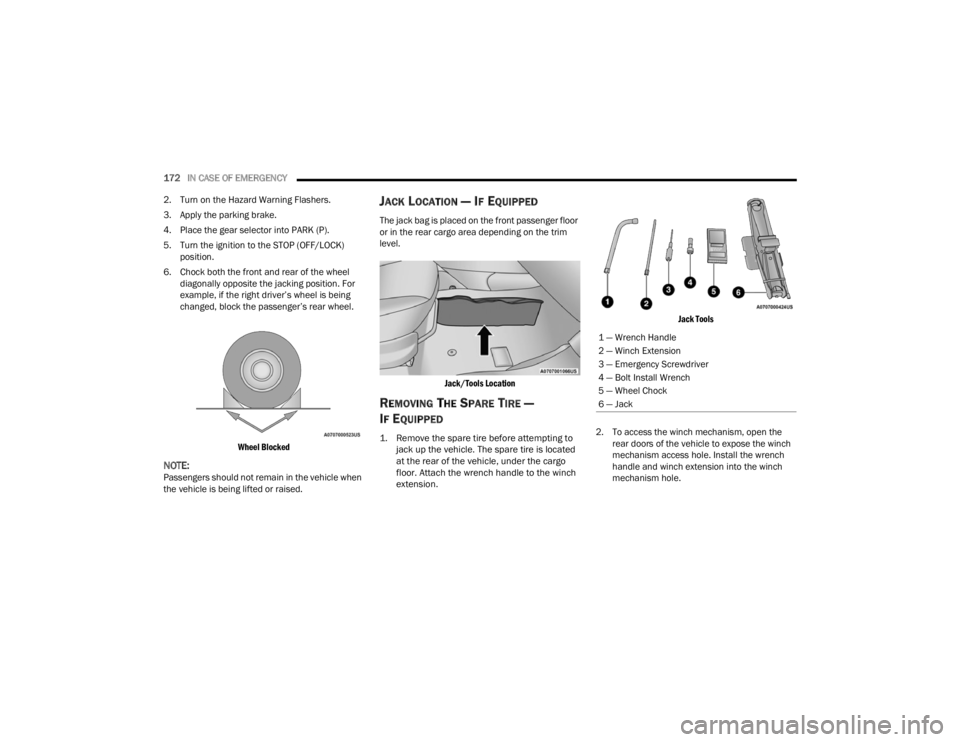
6. Chock both the front and rear of the wheel diagonally opposite the jacking position. For
example, if the right driver’s wheel is being
changed, block the passenger’s rear wheel.
Wheel Blocked
NOTE:Passengers should not remain in the vehicle when
the vehicle is being lifted or raised.
JACK LOCATION — IF EQUIPPED
The jack bag is placed on the front passenger floor
or in the rear cargo area depending on the trim
level.
Jack/Tools Location
REMOVING THE SPARE TIRE —
I
F EQUIPPED
1. Remove the spare tire before attempting to
jack up the vehicle. The spare tire is located
at the rear of the vehicle, under the cargo
floor. Attach the wrench handle to the winch
extension.
Jack Tools
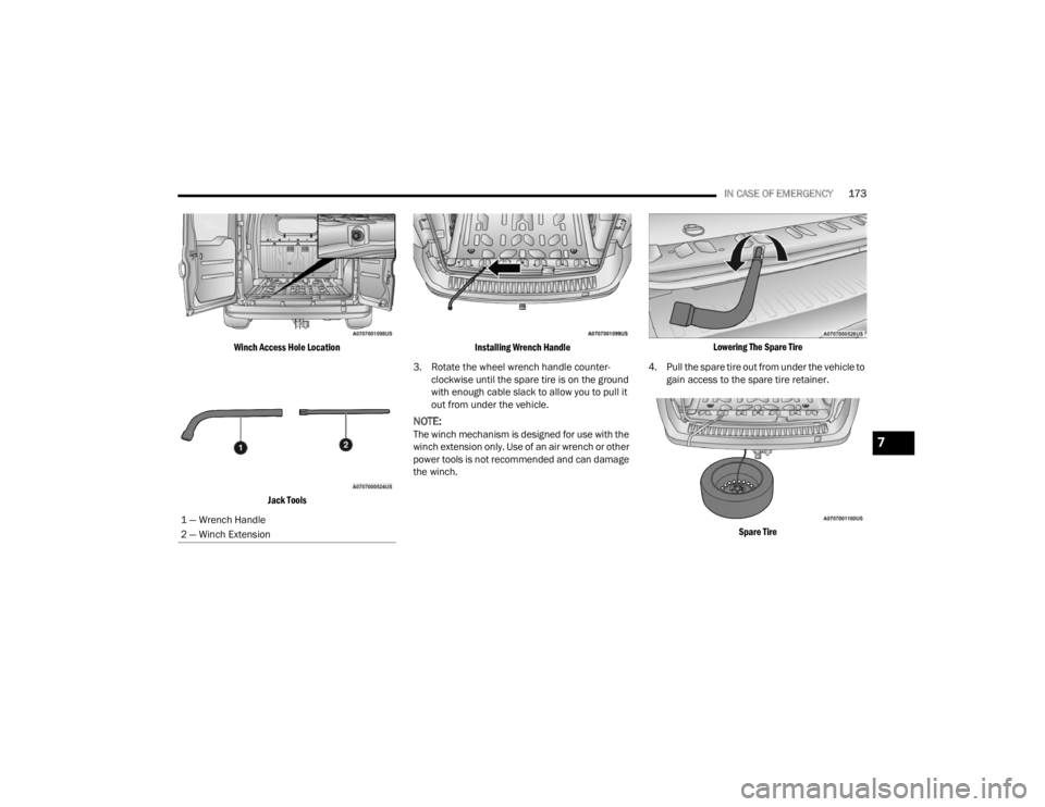
2. To access the winch mechanism, open the rear doors of the vehicle to expose the winch
mechanism access hole. Install the wrench
handle and winch extension into the winch
mechanism hole.
1 — Wrench Handle
2 — Winch Extension
3 — Emergency Screwdriver
4 — Bolt Install Wrench
5 — Wheel Chock
6 — Jack
22_VM_OM_EN_USC_t.book Page 172
Page 175 of 260
IN CASE OF EMERGENCY173
Winch Access Hole Location Jack Tools Installing Wrench Handle
3. Rotate the wheel wrench handle counter -
clockwise until the spare tire is on the ground
with enough cable slack to allow you to pull it
out from under the vehicle.
NOTE:The winch mechanism is designed for use with the
winch extension only. Use of an air wrench or other
power tools is not recommended and can damage
the winch.
Lowering The Spare Tire
4. Pull the spare tire out from under the vehicle to gain access to the spare tire retainer.
Spare Tire
1 — Wrench Handle
2 — Winch Extension7
22_VM_OM_EN_USC_t.book Page 173
Page 176 of 260
174IN CASE OF EMERGENCY
(Continued)
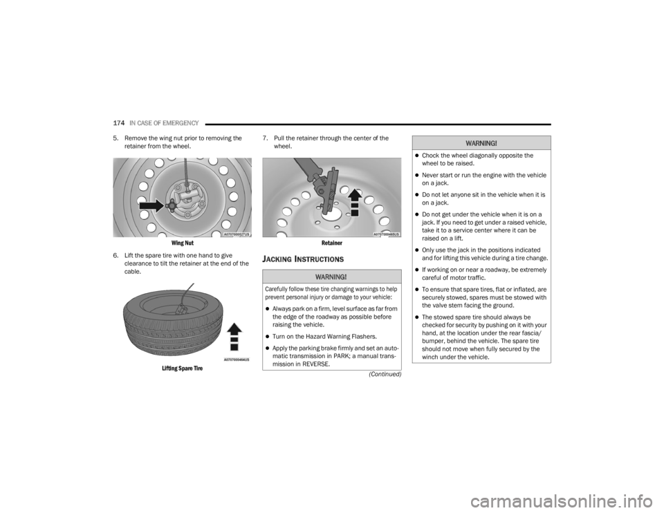
5. Remove the wing nut prior to removing the
retainer from the wheel.
Wing Nut
6. Lift the spare tire with one hand to give clearance to tilt the retainer at the end of the
cable.
Lifting Spare Tire
7. Pull the retainer through the center of the
wheel.
Retainer
JACKING INSTRUCTIONS
WARNING!
Carefully follow these tire changing warnings to help
prevent personal injury or damage to your vehicle:
Always park on a firm, level surface as far from
the edge of the roadway as possible before
raising the vehicle.
Turn on the Hazard Warning Flashers.
Apply the parking brake firmly and set an auto -
matic transmission in PARK; a manual trans -
mission in REVERSE.
Chock the wheel diagonally opposite the
wheel to be raised.
Never start or run the engine with the vehicle
on a jack.
Do not let anyone sit in the vehicle when it is
on a jack.
Do not get under the vehicle when it is on a
jack. If you need to get under a raised vehicle,
take it to a service center where it can be
raised on a lift.
Only use the jack in the positions indicated
and for lifting this vehicle during a tire change.
If working on or near a roadway, be extremely
careful of motor traffic.
To ensure that spare tires, flat or inflated, are
securely stowed, spares must be stowed with
the valve stem facing the ground.
The stowed spare tire should always be
checked for security by pushing on it with your
hand, at the location under the rear fascia/
bumper, behind the vehicle. The spare tire
should not move when fully secured by the
winch under the vehicle.
WARNING!
22_VM_OM_EN_USC_t.book Page 174
Page 178 of 260
176IN CASE OF EMERGENCY
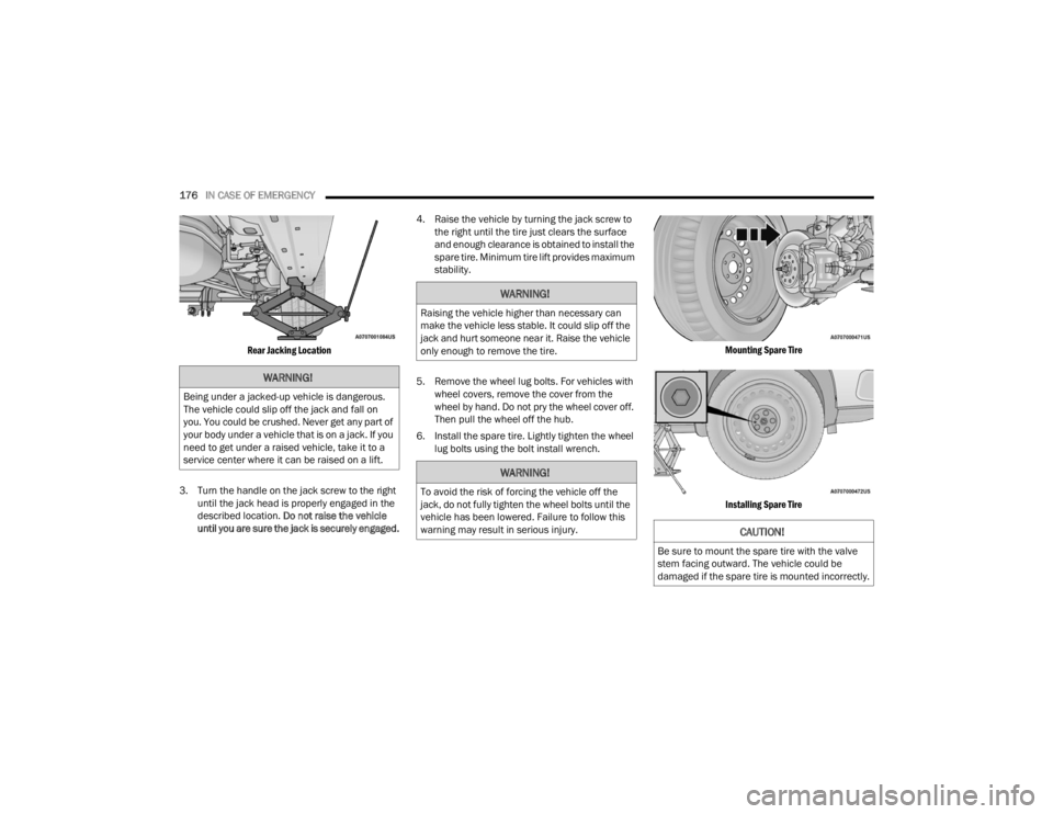
Rear Jacking Location
3. Turn the handle on the jack screw to the right until the jack head is properly engaged in the
described location. Do not raise the vehicle
until you are sure the jack is securely engaged. 4. Raise the vehicle by turning the jack screw to
the right until the tire just clears the surface
and enough clearance is obtained to install the
spare tire. Minimum tire lift provides maximum
stability.
5. Remove the wheel lug bolts. For vehicles with wheel covers, remove the cover from the
wheel by hand. Do not pry the wheel cover off.
Then pull the wheel off the hub.
6. Install the spare tire. Lightly tighten the wheel lug bolts using the bolt install wrench.
Mounting Spare Tire
Installing Spare Tire
WARNING!
Being under a jacked-up vehicle is dangerous.
The vehicle could slip off the jack and fall on
you. You could be crushed. Never get any part of
your body under a vehicle that is on a jack. If you
need to get under a raised vehicle, take it to a
service center where it can be raised on a lift.
WARNING!
Raising the vehicle higher than necessary can
make the vehicle less stable. It could slip off the
jack and hurt someone near it. Raise the vehicle
only enough to remove the tire.
WARNING!
To avoid the risk of forcing the vehicle off the
jack, do not fully tighten the wheel bolts until the
vehicle has been lowered. Failure to follow this
warning may result in serious injury.
CAUTION!
Be sure to mount the spare tire with the valve
stem facing outward. The vehicle could be
damaged if the spare tire is mounted incorrectly.
22_VM_OM_EN_USC_t.book Page 176
Page 179 of 260
IN CASE OF EMERGENCY177
7. Lower the vehicle by turning the jack screw to the left Ú page 236.
8. Lower the jack to its fully-closed position.
9. Stow the cable and wheel spacer before driving the vehicle Ú page 177.
10. Stow the jack and tools under the driver’s seat.
11. Check the spare tire pressure as soon as possible. Correct the tire pressure, as
required.
12. When you place the spare tire back on the winch or if you carry the tire in need of repair
on the winch, always check that the tire is
properly secured under the vehicle by pushing
on the stowed tire under the rear fascia/
bumper at the back of the vehicle. If the tire
has motion when pushed, use the tools to
re-tighten the winch until a loud click is heard.
VEHICLES WITH ALLOY WHEELS
For stowing a damaged tire on vehicles with alloy
wheels, remove the adapter bracket and bolts
from the storage bag in the glove compartment
and follow the steps below:
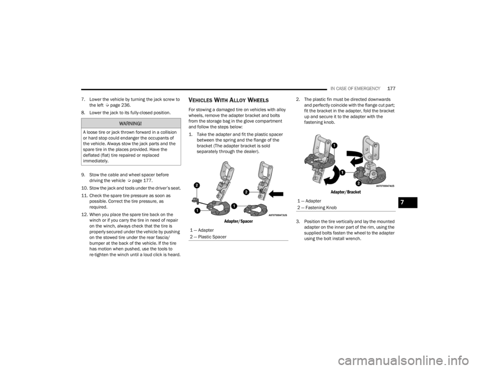
1. Take the adapter and fit the plastic spacer between the spring and the flange of the
bracket (The adapter bracket is sold
separately through the dealer).
Adapter/Spacer
2. The plastic fin must be directed downwards
and perfectly coincide with the flange cut part;
fit the bracket in the adapter, fold the bracket
up and secure it to the adapter with the
fastening knob.
Adapter/Bracket
3. Position the tire vertically and lay the mounted adapter on the inner part of the rim, using the
supplied bolts fasten the wheel to the adapter
using the bolt install wrench.
WARNING!
A loose tire or jack thrown forward in a collision
or hard stop could endanger the occupants of
the vehicle. Always stow the jack parts and the
spare tire in the places provided. Have the
deflated (flat) tire repaired or replaced
immediately.
1 — Adapter
2 — Plastic Spacer
1 — Adapter
2 — Fastening Knob7
22_VM_OM_EN_USC_t.book Page 177