turn signal RAM PROMASTER CITY 2022 Owners Manual
[x] Cancel search | Manufacturer: RAM, Model Year: 2022, Model line: PROMASTER CITY, Model: RAM PROMASTER CITY 2022Pages: 260, PDF Size: 8.45 MB
Page 4 of 260
2
INTRODUCTION
SYMBOLS KEY ...........................................................7
VAN CONVERSIONS/CAMPERS ..............................7
VEHICLE MODIFICATIONS/ALTERATIONS .............7
SYMBOL GLOSSARY.................................................8
GETTING TO KNOW YOUR VEHICLE
KEYS ....................................................................... 10 Key Fob .............................................................10
SENTRY KEY ........................................................... 12
IGNITION SWITCH .................................................. 12
DOORS ................................................................... 13
Power Door Locks ............................................13
Auto Unlock Doors ............................................13
Sliding Side Door ..............................................13
Double Rear Swing Doors ................................15
Child-Protection Door Lock System.................15
STEERING WHEEL.................................................. 16
Tilt/Telescoping Steering Column ...................16
SEATS ...................................................................... 16
Manual Adjustment (Front Seats) ...................16
Folding Rear Seat — If Equipped .....................17
Heated Seats — If Equipped ............................18
Head Restraints ...............................................19 UCONNECT VOICE RECOGNITION ........................21
Introducing Voice Recognition.........................21
Basic Voice Commands ...................................21
Get Started .......................................................21
Additional Information .....................................21
MIRRORS ...............................................................22
Inside Rearview Mirror .....................................22
Vanity Mirror .....................................................22
Outside Mirrors ................................................22
EXTERIOR LIGHTS ..................................................24
Multifunction Lever ..........................................24
Headlights ........................................................24
Daytime Running Lights (DRLs) —
If Equipped .......................................................24
High/Low Beam Switch....................................24
Flash-To-Pass ..................................................24
Parking Lights ..................................................24
Follow Me Home/Headlight Delay ..................24
Fog Lights — If Equipped .................................25
Turn Signals ......................................................25
Lane Change Assist..........................................25
INTERIOR LIGHTS ..................................................25
Courtesy/Interior Lights ...................................25
WIPERS AND WASHERS ......................................26
Front Wiper Operation......................................27
Rear Wiper And Washer —If Equipped ............28 CLIMATE CONTROLS ............................................ 28
Manual Climate Control Descriptions And
Functions .......................................................... 28
Operating Tips .................................................. 30
INTERIOR STORAGE AND EQUIPMENT ............... 31
Storage ............................................................. 31
USB Control — If Equipped .............................. 32
Power Outlets .................................................. 32
WINDOWS ............................................................. 34
Power Window Controls —If Equipped ........... 34
Window Bar Grates — If Equipped .................. 35
Wind Buffeting .................................................35
HOOD....................................................................... 36
Opening............................................................. 36
Closing ..............................................................36
CARGO AREA FEATURES ...................................... 37
Rear Cargo Tie-Downs ..................................... 37
ROOF RACK — IF EQUIPPED................................. 37
GETTING TO KNOW YOUR
INSTRUMENT PANEL
INSTRUMENT CLUSTER......................................... 39
Instrument Cluster Descriptions ..................... 40
INSTRUMENT CLUSTER DISPLAY ....................... 40
Location And Controls...................................... 40
Change Engine Oil — If Equipped ................... 41
Instrument Cluster Display Menu Items ......... 42
22_VM_OM_EN_USC_t.book Page 2
Page 11 of 260
9
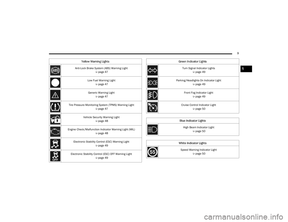
Yellow Warning Lights
Anti-Lock Brake System (ABS) Warning Light Úpage 47
Low Fuel Warning Light Úpage 47
Generic Warning Light Úpage 47
Tire Pressure Monitoring System (TPMS) Warning Light Úpage 47
Vehicle Security Warning Light Úpage 48
Engine Check/Malfunction Indicator Warning Light (MIL) Úpage 48
Electronic Stability Control (ESC) Warning Light Úpage 49
Electronic Stability Control (ESC) OFF Warning Light Úpage 49
Green Indicator Lights
Turn Signal Indicator Lights
Úpage 49
Parking/Headlights On Indicator Light Úpage 49
Front Fog Indicator Light Úpage 49
Cruise Control Indicator Light Úpage 50
Blue Indicator Lights
High Beam Indicator Light
Úpage 50
White Indicator Lights
Speed Warning Indicator Light
Úpage 50
1
22_VM_OM_EN_USC_t.book Page 9
Page 12 of 260
10
GETTING TO KNOW YOUR VEHICLE
KEYS
KEY FOB
Your vehicle uses a key start ignition system which
supports Remote Keyless Entry (RKE). The key fob
allows you to lock or unlock the doors from
distances up to approximately 66 ft (20 m). The
key fob does not need to be pointed at the vehicle
to activate the system. The key fob also contains
an integrated mechanical key, which can be
accessed by pushing the mechanical key release
button.
NOTE:The key fob may not be able to be detected by the
vehicle if it is located next to a mobile phone,
laptop or other electronic device; these devices
may block the key fob’s wireless signal
Úpage 245.
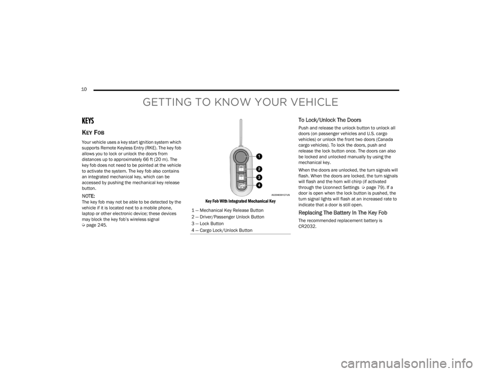
Key Fob With Integrated Mechanical Key
To Lock/Unlock The Doors
Push and release the unlock button to unlock all
doors (on passenger vehicles and U.S. cargo
vehicles) or unlock the front two doors (Canada
cargo vehicles). To lock the doors, push and
release the lock button once. The doors can also
be locked and unlocked manually by using the
mechanical key.
When the doors are unlocked, the turn signals will
flash. When the doors are locked, the turn signals
will flash and the horn will chirp (if activated
through the Uconnect Settings Ú
page 79). If a
door is open when the lock button is pushed, the
turn signal lights will flash at an increased rate to
indicate that a door is still open.
Replacing The Battery In The Key Fob
The recommended replacement battery is
CR2032.
1 — Mechanical Key Release Button
2 — Driver/Passenger Unlock Button
3 — Lock Button
4 — Cargo Lock/Unlock Button
22_VM_OM_EN_USC_t.book Page 10
Page 15 of 260
GETTING TO KNOW YOUR VEHICLE13
NOTE:When opening the driver’s door with the key in the
ignition and the ignition placed in the STOP (OFF/
LOCK) position, a chime will sound to remind you to
remove the key.
DOORS
POWER DOOR LOCKS
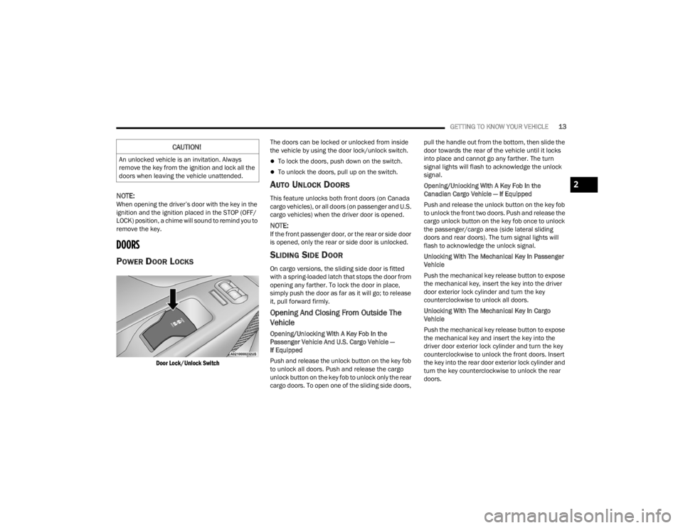
Door Lock/Unlock Switch
The doors can be locked or unlocked from inside
the vehicle by using the door lock/unlock switch.
To lock the doors, push down on the switch.
To unlock the doors, pull up on the switch.
AUTO UNLOCK DOORS
This feature unlocks both front doors (on Canada
cargo vehicles), or all doors (on passenger and U.S.
cargo vehicles) when the driver door is opened.
NOTE:If the front passenger door, or the rear or side door
is opened, only the rear or side door is unlocked.
SLIDING SIDE DOOR
On cargo versions, the sliding side door is fitted
with a spring-loaded latch that stops the door from
opening any farther. To lock the door in place,
simply push the door as far as it will go; to release
it, pull forward firmly.
Opening And Closing From Outside The
Vehicle
Opening/Unlocking With A Key Fob In the
Passenger Vehicle And U.S. Cargo Vehicle —
If Equipped
Push and release the unlock button on the key fob
to unlock all doors. Push and release the cargo
unlock button on the key fob to unlock only the rear
cargo doors. To open one of the sliding side doors, pull the handle out from the bottom, then slide the
door towards the rear of the vehicle until it locks
into place and cannot go any farther. The turn
signal lights will flash to acknowledge the unlock
signal.
Opening/Unlocking With A Key Fob In the
Canadian Cargo Vehicle — If Equipped
Push and release the unlock button on the key fob
to unlock the front two doors. Push and release the
cargo unlock button on the key fob once to unlock
the passenger/cargo area (side lateral sliding
doors and rear doors). The turn signal lights will
flash to acknowledge the unlock signal.
Unlocking With The Mechanical Key In Passenger
Vehicle
Push the mechanical key release button to expose
the mechanical key, insert the key into the driver
door exterior lock cylinder and turn the key
counterclockwise to unlock all doors.
Unlocking With The Mechanical Key In Cargo
Vehicle
Push the mechanical key release button to expose
the mechanical key and insert the key into the
driver door exterior lock cylinder and turn the key
counterclockwise to unlock the front doors. Insert
the key into the rear door exterior lock cylinder and
turn the key counterclockwise to unlock the rear
doors.
CAUTION!
An unlocked vehicle is an invitation. Always
remove the key from the ignition and lock all the
doors when leaving the vehicle unattended.
2
22_VM_OM_EN_USC_t.book Page 13
Page 16 of 260
14GETTING TO KNOW YOUR VEHICLE
Closing/Locking With A Key Fob
Push and release the lock button on the key fob to
lock all doors, including the cargo area (side lateral
sliding doors and rear doors). The turn signal lights
will flash to acknowledge the lock signal.
Horn activation settings after a key fob lock
command can be adjusted manually through the
Uconnect system Ú page 79.
Locking With The Mechanical Key In Passenger
Vehicle
Push the mechanical key release button to expose
the mechanical key, insert the key into the driver
door exterior lock cylinder and turn the key
clockwise to lock all doors.
Locking With The Mechanical Key In Cargo Vehicle
Push the mechanical key release button to expose
the mechanical key, insert the key into the driver
door exterior lock cylinder and turn the key
clockwise to lock the front doors. Insert the key into
the rear door exterior lock cylinder and turn the key
clockwise to lock the rear doors.
Closing And Locking From Outside
Grab the side door handle and push towards the
front of the vehicle. Once the side door is secured
in the full closed position, use one of the prior
locking methods to lock the sliding side doors.
Opening And Closing From The Inside
Opening:
Pull the interior door handle to unlock the door,
then pull the handle and slide the door towards the
rear of the vehicle until it can go no farther.
Closing:
Pull the interior door handle to release the door
and then push it towards the front of the vehicle.
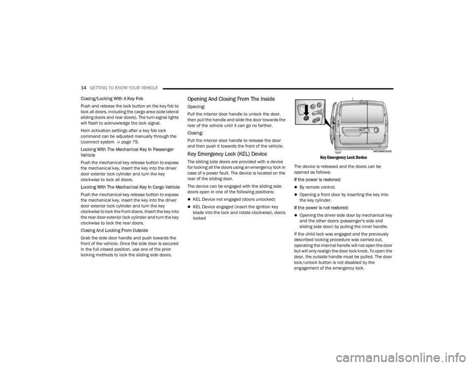
Key Emergency Lock (KEL) Device
The sliding side doors are provided with a device
for locking all the doors using an emergency lock in
case of a power fault. The device is located on the
rear of the sliding door.
The device can be engaged with the sliding side
doors open in one of the following positions:
KEL Device not engaged (doors unlocked)
KEL Device engaged (insert the ignition key
blade into the lock and rotate clockwise), doors
locked
Key Emergency Lock Device
The device is released and the doors can be
opened as follows:
If the power is restored:
By remote control.
Opening a front door by inserting the key into
the key cylinder.
If the power is not restored:
Opening the driver side door by mechanical key
and the other doors (passenger's side and
sliding side door) by pulling the inner handle.
If the child lock was engaged and the previously
described locking procedure was carried out,
operating the internal handle will not open the door
but will only realign the door lock knob. To open the
door, the outside handle must be pulled. The door
lock/unlock button is not disabled by the
engagement of the emergency lock.
22_VM_OM_EN_USC_t.book Page 14
Page 18 of 260
16GETTING TO KNOW YOUR VEHICLE
NOTE:For emergency exit from the rear seats when the
Child-Protection Door Lock system is engaged,
manually raise the door lock knob to the unlocked
position, roll down the window, and open the door
using the outside door handle.
STEERING WHEEL
TILT/TELESCOPING STEERING COLUMN
This feature allows you to tilt the steering column
upward or downward. It also allows you to lengthen
or shorten the steering column. The steering
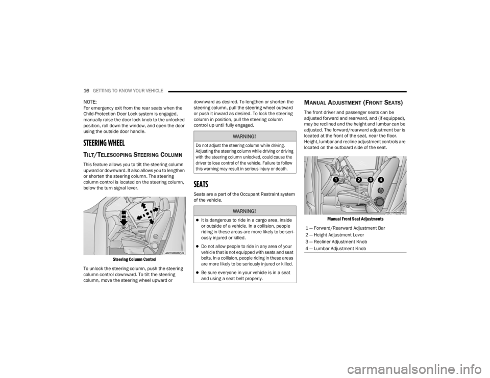
column control is located on the steering column,
below the turn signal lever.
Steering Column Control
To unlock the steering column, push the steering
column control downward. To tilt the steering
column, move the steering wheel upward or downward as desired. To lengthen or shorten the
steering column, pull the steering wheel outward
or push it inward as desired. To lock the steering
column in position, pull the steering column
control up until fully engaged.
SEATS
Seats are a part of the Occupant Restraint system
of the vehicle.
MANUAL ADJUSTMENT (FRONT SEATS)
The front driver and passenger seats can be
adjusted forward and rearward, and (if equipped),
may be reclined and the height and lumbar can be
adjusted. The forward/rearward adjustment bar is
located at the front of the seat, near the floor.
Height, lumbar and recline adjustment controls are
located on the outboard side of the seat.
Manual Front Seat Adjustments
WARNING!
Do not adjust the steering column while driving.
Adjusting the steering column while driving or driving
with the steering column unlocked, could cause the
driver to lose control of the vehicle. Failure to follow
this warning may result in serious injury or death.
WARNING!
It is dangerous to ride in a cargo area, inside
or outside of a vehicle. In a collision, people
riding in these areas are more likely to be seri -
ously injured or killed.
Do not allow people to ride in any area of your
vehicle that is not equipped with seats and seat
belts. In a collision, people riding in these areas
are more likely to be seriously injured or killed.
Be sure everyone in your vehicle is in a seat
and using a seat belt properly.
1 — Forward/Rearward Adjustment Bar
2 — Height Adjustment Lever
3 — Recliner Adjustment Knob
4 — Lumbar Adjustment Knob
22_VM_OM_EN_USC_t.book Page 16
Page 26 of 260
24GETTING TO KNOW YOUR VEHICLE
EXTERIOR LIGHTS
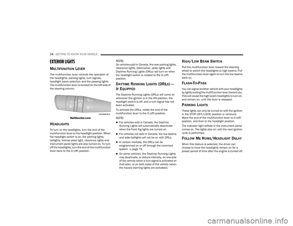
MULTIFUNCTION LEVER
The multifunction lever controls the operation of
the headlights, parking lights, turn signals,
headlight beam selection and the passing lights.
The multifunction lever is located on the left side of
the steering column.
Multifunction Lever
HEADLIGHTS
To turn on the headlights, turn the end of the
multifunction lever to the headlight position. When
the headlight switch is on, the parking lights,
taillights, license plate light, clearance lights and
instrument panel lights are also turned on. To turn
off the headlights, turn the end of the multifunction
lever back to the O (off) position.
NOTE:On vehicles sold in Canada, the rear parking lights,
clearance lights, sidemarker, plate lights and
Daytime Running Lights (DRLs) will turn on when
the headlight switch is rotated to the O (off)
position.
DAYTIME RUNNING LIGHTS (DRLS) —
I
F EQUIPPED
The Daytime Running Lights (DRLs) will come on
whenever the ignition is in the ON position, the
headlight switch is off, and a turn signal has not
been activated.
To activate the DRLs, rotate the end of the
multifunction lever to the O (off) position.
NOTE:
For vehicles sold in Canada, the Daytime
Running Lights will automatically deactivate
when the front fog lights are turned on.
For vehicles not sold in Canada, the low beams
and side/taillights will not be on with DRLs.
In certain markets, the DRLs can be
programmed on or off through the Uconnect
system Ú page 79.
On some vehicles, the Daytime Running Lights
may deactivate, or reduce intensity, on one side
of the vehicle (when a turn signal is activated on
that side), or on both sides of the vehicle (when
the hazard warning lights are activated).
HIGH/LOW BEAM SWITCH
Pull the multifunction lever toward the steering
wheel to switch the headlights to high beams. Pull
the multifunction lever again to turn the low beams
back on.
FLASH-TO-PASS
You can signal another vehicle with your headlights
by lightly pulling the multifunction lever toward you.
This will cause the high beam headlights to turn on,
and remain on, until the lever is released.
PARKING LIGHTS
These lights can only be turned on with the ignition
in the STOP (OFF/LOCK) position or removed.
Move the end of the multifunction lever to O (off)
position, and then to the headlight position.
The indicator light telltale in the instrument panel
comes on. The lights stay on until the next ignition
cycle is performed.
FOLLOW ME HOME/HEADLIGHT DELAY
When this feature is selected, the driver can
choose to have the headlights remain on for a
preset period of time after the engine is turned off.
22_VM_OM_EN_USC_t.book Page 24
Page 27 of 260
GETTING TO KNOW YOUR VEHICLE25
Activation
Remove the key or turn the ignition to the STOP
(OFF/LOCK) position, and pull the multifunction
lever toward the steering wheel within two
minutes. Each time the lever is pulled, the
activation of the lights will be extended by 30
seconds. The activation of the lights can be
extended to a maximum of 210 seconds.
Deactivation
Pull the multifunction lever toward the steering
wheel and hold it for more than two seconds.
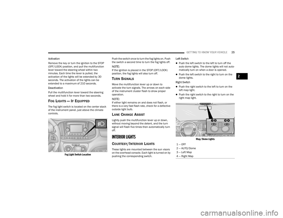
FOG LIGHTS — IF EQUIPPED
The fog light switch is located on the center stack
of the instrument panel, just above the climate
controls.
Fog Light Switch Location
Push the switch once to turn the fog lights on. Push
the switch a second time to turn the fog lights off.
NOTE:If the ignition is placed in the STOP (OFF/LOCK)
position, the fog lights will also turn off.
TURN SIGNALS
Move the multifunction lever up or down to
activate the turn signals. The arrows on each side
of the instrument cluster flash to show proper
operation.
NOTE:If either light remains on and does not flash, or
there is a very fast flash rate, check for a defective
outside light bulb.
LANE CHANGE ASSIST
Lightly push the multifunction lever up or down,
without moving beyond the detent, and the turn
signal will flash five times then automatically turn
off.
INTERIOR LIGHTS
COURTESY/INTERIOR LIGHTS
These lights are mounted between the sun visors
on the overhead console. Each light is turned on by
pushing the corresponding switch. Left Switch
Push the left switch to the left to turn off the
auto dome lights. The dome lights will not auto -
matically turn on when a door is opened.
Push the left switch to the right to turn on the
dome lights.
Right Switch
Push the right switch to the left to turn on the
left map light.
Push the right switch to the right to turn on the
right map light.
Map/Dome Lights
1 — OFF
2 — AUTO/Dome
3 — Left Map
4 — Right Map
2
22_VM_OM_EN_USC_t.book Page 25
Page 44 of 260
42GETTING TO KNOW YOUR INSTRUMENT PANEL
NOTE:If the indicator message illuminates when you start
the vehicle, the oil change indicator system did not
reset. If necessary, repeat this procedure.
INSTRUMENT CLUSTER DISPLAY MENU
I
TEMS
Speed Beep
This function is used to set a speed limit (MPH or
km/h); the driver is alerted when this limit is
exceeded.
To set the desired speed limit:
1. Push the
MENU
button briefly. The display will
show the wording (SPEED BEEP) and the unit
(MPH) or (km/h) previously set.
2. If the function is on, push and release the up
or down arrow button to select the required
speed limit and then push MENU to confirm.
NOTE:The speed may be set in the range from 20 to
125 mph (30 to 200 km/h) according to the previ -
ously chosen unit.
The setting will increase/decrease by five units
each time the up or down arrow button is
pushed. Hold down the up or down arrow
button to automatically increase/decrease the setting rapidly. Complete the adjustment when you
approach the desired value.
Push the
MENU button briefly to return to the menu
screen or hold the MENU button down to return to
the standard screen without storing.
To cancel the setting:
1. Briefly push the
MENU
button, “ON” will flash
in the display.
2. Push the down arrow button, “OFF” will
flash in the display.
3. Push the MENU button briefly to return to the
menu screen or hold the MENU button down to
return to the standard screen without storing.
Trip B Data
This function can be used to activate (On) or
deactivate (Off) the Trip B display (Partial Trip)
Ú page 43.
To switch the function On/Off:
1. Push the
MENU
button briefly. The display will
flash On or Off according to the previous
setting.
2. Push and release the up or down arrow
button to select. Push the
MENU button briefly to return to the menu
screen or hold the MENU button down to return to
the standard screen without storing.
Buzzer Volume
With this function, the volume of the acoustic
signal which accompanies the display of failure/
warning can be adjusted according to seven levels.
To set the desired volume:
1. Push the
MENU
button, the previously set
volume level will flash on the display.
2. Push and release the up or down arrow
button to adjust.
3. Push the MENU button to return to the menu
screen or hold the MENU button down to
return to the standard screen without storing.
Seat Belt Buzzer
Only shows in the instrument cluster display if the
seat belt reminder was previously deactivated by
an authorized dealer.
NOTE:This is a one-time occurrence to enable the
acoustic signal.
22_VM_OM_EN_USC_t.book Page 42
Page 46 of 260
44GETTING TO KNOW YOUR INSTRUMENT PANEL
“Trip B” can be used to display the figures relating to:
Trip distance B
Average Economy B
Average speed B
Travel time B (driving time)
NOTE:“Trip B” functions may be excluded (see “Trip B
Data”). Range and Instantaneous Economy cannot
be reset.
VALUES DISPLAYED
Range
This indicates the distance which may be traveled
with the fuel remaining in the tank, assuming that
driving conditions will not change. The message “----”
will appear on the display in the following cases:
Distance less than 30 miles (or 50 km).
The vehicle is parked for a long time with the
engine running.
NOTE:The range depends on several factors: driving
style, type of route (freeway, residential, mountain
roads, etc.), conditions of use of the vehicle (load,
tire pressure, etc.). Trip planning must take into
account the above notes.
Travel Distance
This value shows the distance covered since the
last reset.
Average Fuel Consumption
This value shows the approximate average
consumption since the last reset.
Current Fuel Consumption
This indicates the fuel consumption. The value is
constantly updated. The message “----” will appear
on the display if the vehicle is parked with the
engine running.
Average Speed
This value shows the vehicle's average speed as a
function of the overall time elapsed since the last
reset.
Travel Time
This value shows the time elapsed since the last
reset.
WARNING LIGHTS AND MESSAGES
The warning/indicator lights will illuminate in the
instrument panel together with a dedicated
message and/or acoustic signal when applicable.
These indications are indicative and precautionary
and as such must not be considered as exhaustive
and/or alternative to the information contained in
the Owner’s Manual, which you are advised to read
carefully in all cases. Always refer to the information
in this chapter in the event of a failure indication. All
active telltales will display first if applicable. The
system check menu may appear different based
upon equipment options and current vehicle status.
Some telltales are optional and may not appear.
RED WARNING LIGHTS
Air Bag Warning Light
This light will turn on for four to eight
seconds as a bulb check when the
ignition is placed in the ON/RUN or
MAR/ON/RUN position. If the light is
either not on during startup, stays on, or turns on
while driving, have the system inspected by an
authorized dealer as soon as possible. This light
will illuminate with a single chime when a fault with
the Air Bag Warning Light has been detected, it will
stay on until the fault is cleared. If the light comes
on intermittently or remains on while driving, have
an authorized dealer service the vehicle
immediately.
22_VM_OM_EN_USC_t.book Page 44