display RENAULT ALASKAN 2017 Owners Manual
[x] Cancel search | Manufacturer: RENAULT, Model Year: 2017, Model line: ALASKAN, Model: RENAULT ALASKAN 2017Pages: 340, PDF Size: 6.93 MB
Page 199 of 340
PHONEBOOK
To access the vehicle phonebook:
1. Push the button on the control panel.
2. Select the “Contacts” key.
3. Choose the desired entry from the displayed list.
4. The number of the entry will be displayed on the screen. Touch the number to initiate dialling.
NOTE
To scroll quickly through the list, touch the “A-Z”
key in the upper right corner of the screen. Turn
the ENTER/Scroll dial to choose aletter or num-
ber and then push the ENTER/Scroll dial. The list
will move to the first entry that begins with that
number or letter.
MAKING ACALL
To make acall, follow the procedure below:
1. Push the on the control panel. The “Phone”
screen will appear on the display.
2. Select one of the following options to make a call:
• “Contacts”: Select the name from an entry
stored in the vehicle phonebook.
• “Call Lists”: Select the name from the incom-
ing, outgoing or missed.
• “Redial”: Dial the last outgoing call from the
vehicle. •
“ ”: Input the phone number manually us-
ing akeypad displayed on the screen. For
information on how to use the touch screen,
see “How to use touch screen display” in this
section.
RECEIVING ACALL
When acall is placed to the connected phone, the
display will change to phone mode.
To accept the incoming call, take one of the follow-
ing actions.
• Push the button on the steering wheel.
• Touch the “ ”i
con on the screen.
To reject the incoming call, take one of the following
actions.
• Push the button on the steering wheel.
• Touch the red phone “ ”i
con on the screen.
DURING ACALL
While acall is active, the following options are avail-
able on the screen:
• “Handset”
Select this option to switch control of the phone
call over to the handset.
• “Mute Mic.”
Select this option to mute the microphone. Se-
lect again to reactivate the microphone. •
“ ”i
con
Select to end the phone call.
ENDING ACALL
To end aphone call, select the [ ]i
con on the
screen or push the < >b
utton on the steering
wheel.
BLUETOOTH® SETTINGS
To access the Bluetooth® settings screen:
1. Push the
2. Touch the [Telephone &Bluetooth] key.
Available setting items:
• [Telephone Setup]
See “Telephone setup” later in this section for
details.
• [Pair New Device]
Select to pair
anew Bluetooth® device to the
Bluetooth® Hands-Free Phone System.
• [Select Paired Device]
Select to choose
aBluetooth® device from alist
of those devices paired to the Bluetooth®
Hands-Free Phone System.
• [Delete Paired Device]
Select to delete
aBluetooth® device from alist
of those devices connected/paired to the
Bluetooth® Hands-Free Phone System.
Display screen, heater and air conditioner, and audio system 4-67
Page 200 of 340
![RENAULT ALASKAN 2017 Owners Manual •
[Bluetooth]
Select to toggle Bluetooth®
ONorOFF.
TELEPHONE SETUP
To access the phone settings screen:
1. Push the <SETUP> button.
2. Touch the [Telephone &Bluetooth] key.
3. Touch the [Telephone RENAULT ALASKAN 2017 Owners Manual •
[Bluetooth]
Select to toggle Bluetooth®
ONorOFF.
TELEPHONE SETUP
To access the phone settings screen:
1. Push the <SETUP> button.
2. Touch the [Telephone &Bluetooth] key.
3. Touch the [Telephone](/img/7/58394/w960_58394-199.png)
•
[Bluetooth]
Select to toggle Bluetooth®
ONorOFF.
TELEPHONE SETUP
To access the phone settings screen:
1. Push the
2. Touch the [Telephone &Bluetooth] key.
3. Touch the [Telephone Setup] key.
Available setting items:
• [Sort Phonebook By]*
Select [First Name] or [Last Name] to choose
how phonebook entries are alphabetically dis-
played on the screen.
• [Phonebook]*
Select [Phone] to use the handset’s phonebook.
Select [SIM] to use the phonebook on the SIM
card. Select [Both] to use both sources.
• [Download Phonebook Now]
Select to download the phonebook to the ve-
hicle from the chosen source.
• [Phone Notifications for]
Select [Driver] to have phone notifications shown
in the vehicle information display. Select [Both]
to have phone notifications shown in both the
vehicle information display and the display.
*: These items are only available after the phonebook
has been downloaded.
4-68 Display screen, heater and air conditioner, and audio system
Page 201 of 340

NOTE
Display screen, heater and air conditioner, and audio system
4-69
Page 202 of 340
5
Starting and driving
Starting and driving
Running-in schedule ................................................ 5-2
Before starting engine.............................................. 5-2
Precautions when starting and driving ...................... 5-3 Exhaust gas (carbon monoxide) .......................... 5-3
AdBlue® Selective Catalytic Reduction (SCR)
system (where fitted for diesel engine model) ...... 5-3
Diesel Particulate Filter (DPF) (where fitted) ............. 5-5 Automatic regeneration ....................................... 5-6
On-road and off-road driving precautions ................. 5-6 Driving safety precautions ................................... 5-6
Turbocharger system ............................................... 5-8
Care when driving ................................................... 5-8 Engine cold start period ...................................... 5-8
Loading luggage ................................................. 5-8
Driving in wet conditions ..................................... 5-8
Driving in winter conditions ................................. 5-8
Tyre Pressure Monitoring System (TPMS) (where
fitted) ....................................................................... 5-9 Meter information................................................ 5-12
Activation............................................................ 5-12
New and repositioned TPMS sensors
(including fitment of alternative wheels) ............... 5-12
Adjusting TPMS target pressure ......................... 5-13
Tyre pressure units ............................................. 5-13
[Check cold tyre] message ................................. 5-13
TPMS temperature calibration............................. 5-13
Ignition switch (models without Remote Control
Key system) ............................................................. 5-14
Manual Transmission (MT) .................................. 5-14
Key positions ...................................................... 5-14 Steering lock ...................................................... 5-14
Push-button ignition switch (models with Remote
Control Key system) ................................................ 5-15 Precautions on push-button ignition switch
operation ............................................................ 5-15
Remote Control Key system................................ 5-15
Automatic Transmission (AT) .............................. 5-16
Steering lock ...................................................... 5-16
Ignition switch positions ...................................... 5-16
Remote Control Key battery discharge ................ 5-17
Starting engine (models without Remote Control
Key system) ............................................................. 5-18
Starting engine (models with Remote Control Key
system).................................................................... 5-18
Driving the vehicle.................................................... 5-19 Driving with Automatic Transmission (AT) ........... 5-19
Driving with Manual Transmission (MT) ............... 5-22
Stop/Start System (where fitted) .............................. 5-23
Stop/Start System display................................... 5-24
Stop/Start OFF switch ....................................... 5-25
Four-Wheel Drive (4WD) (where fitted) .................... 5-26 Part time 4WD system ........................................ 5-26
4WD mode switch operation............................... 5-30
4WD mode indicator........................................... 5-30
4WD warning ..................................................... 5-31
Tyre recommendation for 4WD ........................... 5-32
Rear differential locking system (where fitted)........... 5-32
Electronic Stability Programme (ESP) system
(where fitted) ........................................................... 5-33
Page 206 of 340
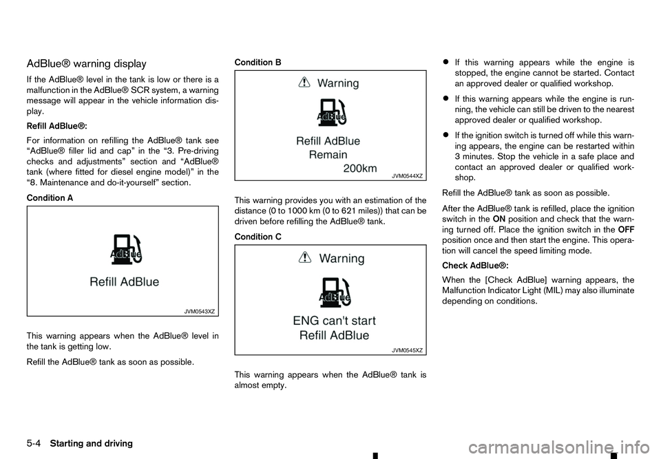
AdBlue® warning display
If the AdBlue® level in the tank is low or there is a malfunction in the AdBlue® SCR system, awarning
message will appear in the vehicle information dis- play.
Refill AdBlue®:
For information on refilling the AdBlue® tank see
“AdBlue® filler lid and cap” in the “3. Pre-driving
checks and adjustments” section and “AdBlue®
tank (where fitted for diesel engine model)” in the
“8. Maintenance and do-it-yourself” section.
Condition A
This warning appears when the AdBlue® level in
the tank is getting low.
Refill the AdBlue® tank as soon as possible. Condition B
This warning provides you with an estimation of the
distance (0 to 1000 km (0 to 621 miles)) that can be
driven before refilling the AdBlue® tank.
Condition C
This warning appears when the AdBlue® tank is
almost empty.•
If this warning appears while the engine is
stopped, the engine cannot be started. Contact
an approved dealer or qualified workshop.
• If this warning appears while the engine is run-
ning, the vehicle can still be driven to the nearest
approved dealer or qualified workshop.
• If the ignition switch is turned off while this warn-
ing appears, the engine can be restarted within
3m
inutes. Stop the vehicle in asafe place and
contact an approved dealer or qualified work-
shop.
Refill the AdBlue® tank as soon as possible.
After the AdBlue® tank is refilled, place the ignition
switch in the ONposition and check that the warn-
ing turned off. Place the ignition switch in the OFF
position once and then start the engine. This opera-
tion will cancel the speed limiting mode.
Check AdBlue®:
When the [Check AdBlue] warning appears, the
Malfunction Indicator Light (MIL) may also illuminate
depending on conditions. JVM0543XZ JVM0544XZ
JVM0545XZ
5-4 Starting and driving
Page 211 of 340
•
Avoid sudden steering.
• Avoid following too close to the vehicle in front.
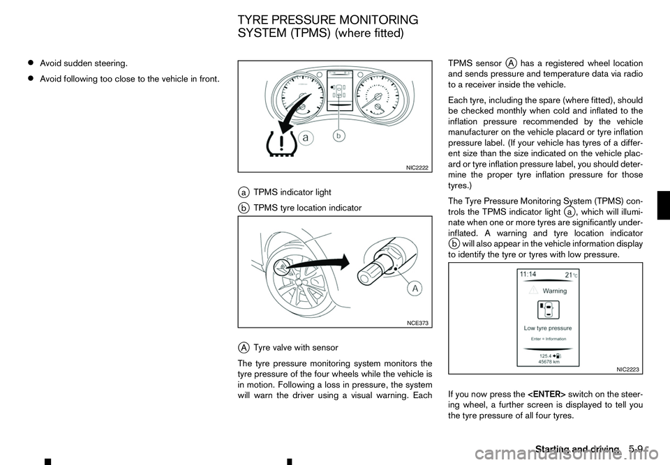
ja TPMS indicator light
j b TPMS tyre location indicator
j A Tyre valve with sensor
The tyre pressure monitoring system monitors the
tyre pressure of the four wheels while the vehicle is
in motion. Following aloss in pressure, the system
will warn the driver using avisual warning. Each TPMS sensor
jAh asaregistered wheel location
and sends pressure and temperature data via radio
to ar eceiver inside the vehicle.
Each tyre, including the spare (where fitted), should
be checked monthly when cold and inflated to the
inflation pressure recommended by the vehicle
manufacturer on the vehicle placard or tyre inflation
pressure label. (If your vehicle has tyres of adiffer-
ent size than the size indicated on the vehicle plac-
ard or tyre inflation pressure label, you should deter-
mine the proper tyre inflation pressure for those
tyres.)
The Tyre Pressure Monitoring System (TPMS) con-
trols the TPMS indicator light j
a, which will illumi-
nate when one or more tyres are significantly under-
inflated. Awarning and tyre location indicator
j bw ill also appear in the vehicle information display
to identify the tyre or tyres with low pressure.
If you now press the
ing wheel, afurther screen is displayed to tell you
the tyre pressure of all four tyres. NIC2222
NCE373
NIC2223
TYRE PRESSURE MONITORING
SYSTEM (TPMS) (where fitted)
Starting and driving5-9
Page 215 of 340
•
Driving below 25 km/h (16 MPH)
• Driving above 100 km/h (64 MPH)
• High acceleration
• High deceleration
• In stop and go traffic or traffic waves
ADJUSTING TPMS TARGET
PRESSURE
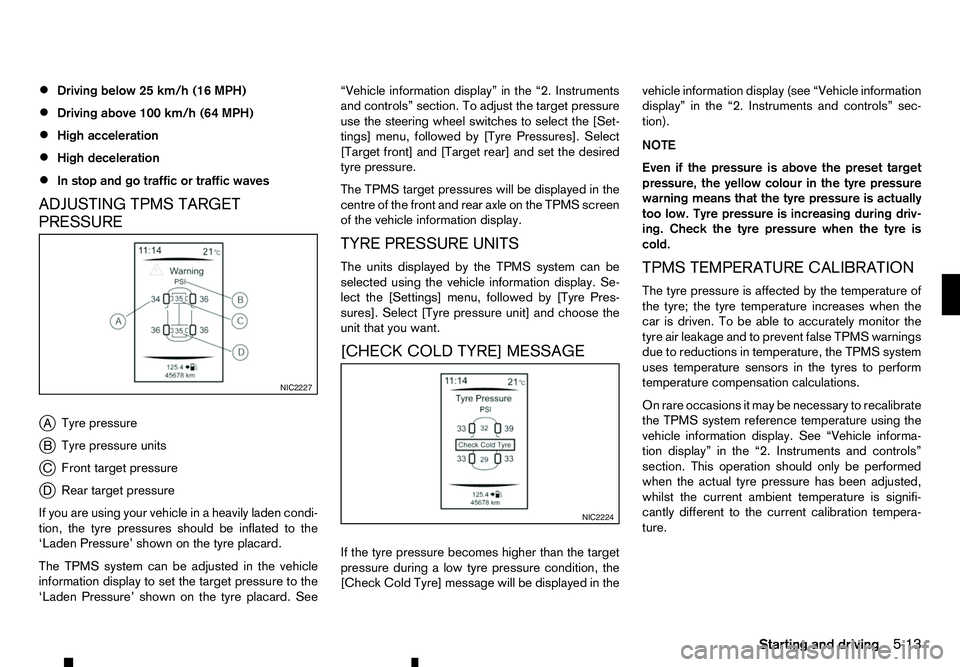
j A Tyre pressure
j B Tyre pressure units
j C Front target pressure
j D Rear target pressure
If you are using your vehicle in aheavily laden condi-
tion, the tyre pressures should be inflated to the
‘Laden Pressure’ shown on the tyre placard.
The TPMS system can be adjusted in the vehicle
information display to set the target pressure to the
‘Laden Pressure’ shown on the tyre placard. See “Vehicle information display” in the “2. Instruments
and controls” section. To adjust the target pressure
use the steering wheel switches to select the [Set-
tings] menu, followed by [Tyre Pressures]. Select
[Target front] and [Target rear] and set the desired
tyre pressure.
The TPMS target pressures will be displayed in the centre of the front and rear axle on the TPMS screen
of the vehicle information display.
TYRE PRESSURE UNITS
The units displayed by the TPMS system can be
selected using the vehicle information display. Se-
lect the [Settings] menu, followed by [Tyre Pres-
sures]. Select [Tyre pressure unit] and choose the
unit that you want.
[CHECK COLD TYRE] MESSAGE
If the tyre pressure becomes higher than the target
pressure during alow tyre pressure condition, the
[Check Cold Tyre] message will be displayed in the vehicle information display (see “Vehicle information
display” in the “2. Instruments and controls” sec-
tion).
NOTE
Even if the pressure is above the preset target
pressure, the yellow colour in the tyre pressure
warning means that the tyre pressure is actually
too low. Tyre pressure is increasing during driv-
ing. Check the tyre pressure when the tyre is
cold.
TPMS TEMPERATURE CALIBRATION
The tyre pressure is affected by the temperature of
the tyre; the tyre temperature increases when the
car is driven. To be able to accurately monitor the
tyre air leakage and to prevent false TPMS warnings
due to reductions in temperature, the TPMS system
uses temperature sensors in the tyres to perform
temperature compensation calculations.
On rare occasions it may be necessary to recalibrate
the TPMS system reference temperature using the
vehicle information display. See “Vehicle informa-
tion display” in the “2. Instruments and controls”
section. This operation should only be performed
when the actual tyre pressure has been adjusted,
whilst the current ambient temperature is signifi-
cantly different to the current calibration tempera-
ture. NIC2227
NIC2224
Starting and driving
5-13
Page 216 of 340
![RENAULT ALASKAN 2017 Owners Manual To initiate TPMS temperature calibration use the
steering wheel switches to select the [Settings]
menu, followed by [Tyre Pressures]. Select [Cali-
brate] followed by [Start]. While the calibration pr RENAULT ALASKAN 2017 Owners Manual To initiate TPMS temperature calibration use the
steering wheel switches to select the [Settings]
menu, followed by [Tyre Pressures]. Select [Cali-
brate] followed by [Start]. While the calibration pr](/img/7/58394/w960_58394-215.png)
To initiate TPMS temperature calibration use the
steering wheel switches to select the [Settings]
menu, followed by [Tyre Pressures]. Select [Cali-
brate] followed by [Start]. While the calibration pro-
cess is active, the message: [Resetting tyre pres-
sure system] will be displayed in the vehicle informa-
tion display. WARNING
Never remove the key or turn the ignition switch
to the
ing wheel will lock. This will cause the driver to
lose control of the vehicle and could result in
serious vehicle damage or personal injury.
MANUAL TRANSMISSION (MT)
The switch includes an anti-theft steering lock de-
vice.
The ignition key can only be removed when theswitch is in the
(0).
There is an “OFF” position ➀in between
and
cylinder.
To lock the steering wheel, remove the key. To
unlock the steering wheel, insert the key and turn
it gently while rotating the steering wheel slightly
right and left. KEY POSITIONS
LOCK (Normal parking position) (0):
The ignition key can only be removed at this posi-
tion.
OFF (1):
The engine can be turned off without locking the
steering wheel.
ACC (Accessories) (2):
This position activates electrical accessories such
as the radio when the engine is not running.
ON (Normal operating position) (3):
This position turns on the ignition system and elec-
trical accessories.
START (4):
This position starts the engine. As soon as the en-
gine has started, release the key immediately. It will
automatically return to the
STEERING LOCK
Locking the steering wheel
1) Place the ignition switch in the
tion.
2) Remove the key from the ignition switch.
3) Turn the steering wheel 1/6 of aturn clockwise
from the straight up position. SSD0392Z
IGNITION SWITCH (models without
Remote Control Key system)
5-14 Starting and driving
Page 217 of 340
Unlocking the steering wheel
1) Insert the key into the ignition switch.
2) Gently turn the ignition switch while rotating the steering wheel left and right. PRECAUTIONS ON PUSH-BUTTON
IGNITION SWITCH OPERATION WARNING
Do not operate the push-button ignition switch
while driving the vehicle except in an emergency.
(The engine will stop when the ignition switch is
pushed 3consecutive times or the ignition switch
is pushed and held for more than 2seconds.)
The steering wheel may lock and could cause
the driver to lose control of the vehicle. This could
result in serious vehicle damage or personal in-
jury.
REMOTE CONTROL KEY SYSTEM
The Remote Control Key system can operate the
ignition switch without taking the key out from your
pocket or bag. The operating environment and/or
conditions may affect the Remote Control Key sys-
tem operation.
Some indicators and warnings for operation are dis-
played in the vehicle information display and/or in
the meter. (See “Warning lights, indicator lights and
audible reminders” in the “2. Instruments and
controls” section and “Vehicle information display”
in the “2. Instruments and controls” section.)
CAUTION
• Be sure to carry the Remote Control Key with
you when operating the vehicle.
• Never leave the Remote Control Key inside
the vehicle when you leave the vehicle. •
If the vehicle battery is discharged, the igni-
tion switch cannot be switched from the
“LOCK” position, and if the steering lock is
engaged, the steering wheel cannot be
moved. Charge the battery as soon as pos-
sible. (See “Remote Control Key battery
replacement” in the “8. Maintenance and
do-it-yourself” section.)
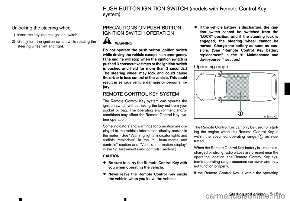
Operating range
The Remote Control Key can only be used for start-
ing the engine when the Remote Control Key is
within the specified operating range ➀as illus-
trated.
When the Remote Control Key battery is almost dis-
charged or strong radio waves are present near the
operating location, the Remote Control Key sys-
tem’s operating range becomes narrower and may
not function properly.
If the Remote Control Key is within the operating JVS0442XZ
PUSH-BUTTON IGNITION SWITCH (models with Remote Control Key
system)
Starting and driving5-15
Page 218 of 340
range, it is possible for anyone, even someone who
does not carry the Remote Control Key, to push the
ignition switch to start the engine.
• The cargo bed area is not included in the operat-
ing range of the engine start function.
• If the Remote Control Key is placed on the in-
strument panel, inside the glove box, door pocket
or the corner of the interior compartment, the
Remote Control Key may not function.
• If the Remote Control Key is placed near the
door or window outside the vehicle, the Remote
Control Key may function.
AUTOMATIC TRANSMISSION (AT)
The ignition lock is designed so that the ignition
switch cannot be switched to the “LOCK” position
until the shift lever is moved to the P(Park) position.
When pushing the ignition switch to the “OFF” posi-
tion, make sure the shift lever is in the P(Park) posi-
tion.
When the ignition switch cannot be switched to the
“LOCK” position:
1. [Shift to Park] warning appears on the vehicle
information display and achime sounds.
2. Move the shift lever to the P(Park) position.
3. If the ignition switch is in the “ACC” position, [PUSH] warning appears on the vehicle informa-
tion display.
4. Push the ignition switch. The ignition switch is switched to the “OFF” position. 5. Open the door. The ignition switch turns to the
“LOCK” position.
For warnings and indicators on the vehicle informa-
tion display, see “Indicators for operation” in the
“2. Instruments and controls” section.
If the ignition switch is switched to the “LOCK”
position, the shift lever cannot be moved from the P
(Park) position. The shift lever can be moved if the
ignition switch is in the “ON” position with the foot-
brake pedal depressed.
STEERING LOCK
The ignition switch is equipped with an anti-theft
steering lock device.
To lock steering wheel
1. Place the ignition switch in the “OFF” position where the ignition switch position indicator will
not illuminate.
2. Open or close the door. The ignition switch turns to the “LOCK” position.
3. Turn the steering wheel 1/6 of aturn to the right
or left from the straight up position.
To unlock steering wheel
Push the ignition switch, and the steering wheel will
be automatically unlocked.
CAUTION
• If the battery of the vehicle is discharged, the
push-button ignition switch cannot be
switched from the “LOCK” position. •
If the steering lock release malfunction indi-
cator (where fitted) appears in the vehicle in-
formation display, push the ignition switch
again while rotating the steering wheel slightly
to the right and left. (See “Vehicle information
display” in the “2. Instruments and controls”
section.)
IGNITION SWITCH POSITIONS WARNING
Never place the ignition switch in the “OFF” posi-
tion while driving. The steering wheel may lock
and cause the driver to lose control of the ve-
hicle, resulting in serious vehicle damage or per-
sonal injury.
CAUTION
• Do not leave the vehicle for extended periods
of time when the ignition switch is in the “ON”
position and the engine is not running. This
can discharge the battery.
• Use electrical accessories with the engine
running to avoid discharging the vehicle bat-
tery. If you must use accessories while the
engine is not running, do not use them for
extended periods of time and do not use mul-
tiple electrical accessories at the same time.
5-16 Starting and driving