engine RENAULT ALASKAN 2017 Owners Manual
[x] Cancel search | Manufacturer: RENAULT, Model Year: 2017, Model line: ALASKAN, Model: RENAULT ALASKAN 2017Pages: 340, PDF Size: 6.93 MB
Page 7 of 340
0
Illustrated table of contents
Illustrated table of contents
Seats, seat belts and Supplemental Restraint
System (SRS).......................................................... 0-2
Exterior front ............................................................ 0-3
Exterior rear ............................................................. 0-4
Passenger compartment .......................................... 0-5
Cockpit ................................................................... 0-6 Left-Hand Drive (LHD) model.............................. 0-6 Right-Hand Drive (RHD) model ........................... 0-7
Instrument panel ...................................................... 0-8 Left-Hand Drive (LHD) model.............................. 0-8
Right-Hand Drive (RHD) model ........................... 0-9
Meters and gauges .................................................. 0-10
Engine compartment ................................................ 0-11 M9T 2.3DCI engine ............................................ 0-11
Page 16 of 340

1.
Tachometer (P. 2-3)
2. Warning and indicator lights (P. 2-3)
3. Vehicle information display (P. 2-14)
—F
our-Wheel Drive (4WD) mode indicator*
(P. 5-30)
—O il control system* (P. 2-29)
—O dometer/twin trip odometer (P. 2-3)
—T rip computer (P. 2-21) —I
nstrument brightness control (P. 2-4)
—A utomatic Transmission (AT) position
indicator (AT model) (P. 2-28, P. 5-19)
4. Speedometer (P. 2-2)
5. Fuel gauge (P. 2-2)
6. Engine coolant temperature gauge (P. 2-3)
*: where fitted NIC2681
METERS AND GAUGES
0-10 Illustrated table of contents
Page 17 of 340
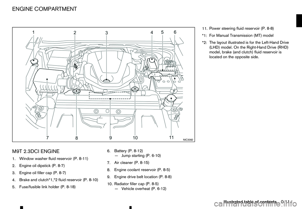
M9T 2.3DCI ENGINE
1. Window washer fluid reservoir (P. 8-11)
2. Engine oil dipstick (P. 8-7)
3. Engine oil filler cap (P. 8-7)
4. Brake and clutch*1,*2 fluid reservoir (P. 8-10)
5. Fuse/fusible link holder (P. 8-18) 6.
Battery (P. 8-12)
—J
ump starting (P. 6-10)
7. Air cleaner (P. 8-15)
8. Engine coolant reservoir (P. 8-5)
9. Engine drive belt location (P. 8-8)
10. Radiator filler cap (P. 8-5)
—V
ehicle overheat (P. 6-12) 11.
Power steering fluid reservoir (P. 8-8)
*1: For Manual Transmission (MT) model
*2: The layout illustrated is for the Left-Hand Drive
(LHD) model. On the Right-Hand Drive (RHD)
model, brake (and clutch) fluid reservoir is
located on the opposite side. NIC3082
ENGINE COMPARTMENT
Illustrated table of contents0-11
Page 21 of 340
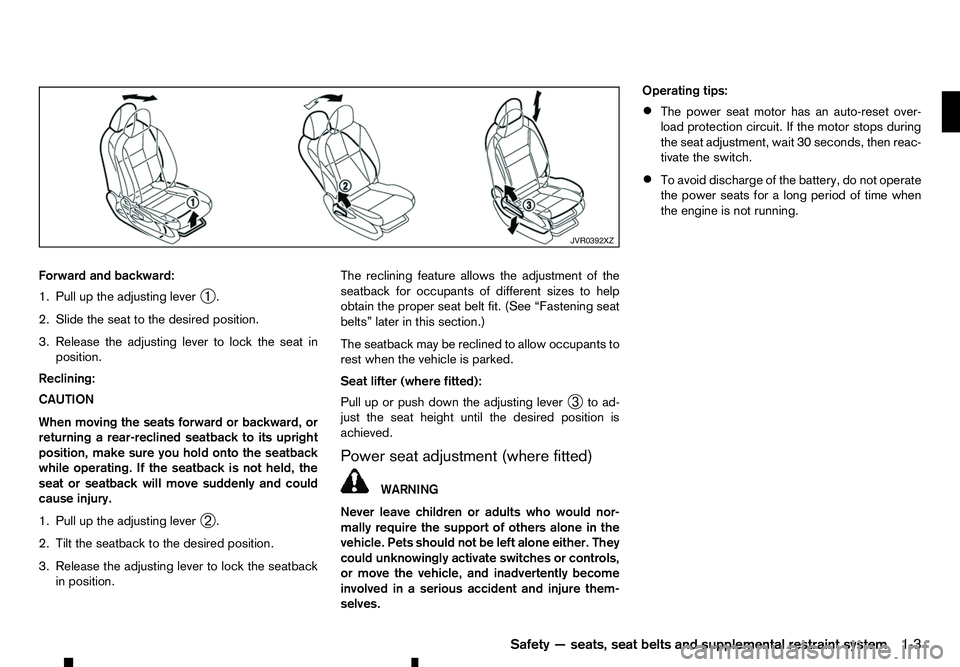
Forward and backward:
1. Pull up the adjusting lever ➀.
2. Slide the seat to the desired position.
3. Release the adjusting lever to lock the seat in position.
Reclining:
CAUTION
When moving the seats forward or backward, or
returning arear-reclined seatback to its upright
position, make sure you hold onto the seatback
while operating. If the seatback is not held, the
seat or seatback will move suddenly and could
cause injury.
1. Pull up the adjusting lever ➁.
2. Tilt the seatback to the desired position.
3. Release the adjusting lever to lock the seatback in position. The reclining feature allows the adjustment of the
seatback for occupants of different sizes to help
obtain the proper seat belt fit. (See “Fastening seat
belts” later in this section.)
The seatback may be reclined to allow occupants to
rest when the vehicle is parked.
Seat lifter (where fitted):
Pull up or push down the adjusting lever ➂to ad-
just the seat height until the desired position is
achieved.
Power seat adjustment (where fitted) WARNING
Never leave children or adults who would nor-
mally require the support of others alone in the
vehicle. Pets should not be left alone either. They
could unknowingly activate switches or controls,
or move the vehicle, and inadvertently become
involved in aserious accident and injure them-
selves. Operating tips:
• The power seat motor has an auto-reset over-
load protection circuit. If the motor stops during
the seat adjustment, wait 30 seconds, then reac-
tivate the switch.
• To avoid discharge of the battery, do not operate
the power seats for
along period of time when
the engine is not running. JVR0392XZ
Safety —seats, seat belts and supplemental restraint system
1-3
Page 23 of 340
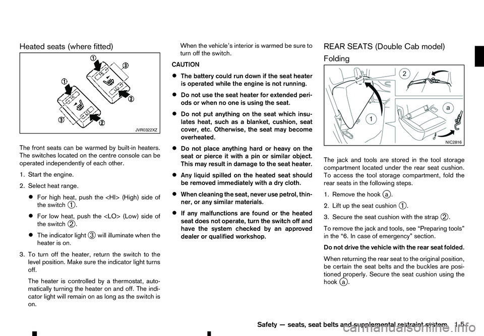
Heated seats (where fitted)
The front seats can be warmed by built-in heaters.
The switches located on the centre console can be
operated independently of each other.
1. Start the engine.
2. Select heat range. • For high heat, push the (High) side of
the switch
➀.
• For low heat, push the
Page 59 of 340
2
Instruments and controls
Instruments and controls
Meters and gauges .................................................. 2-2 Speedometer and Fuel gauge ............................. 2-2
Tachometer and Engine coolant temperature
gauge ................................................................. 2-3
Instrument brightness control .............................. 2-4
Warning lights, indicator lights and audible
reminders ................................................................ 2-5 Checking lights................................................... 2-6
Warning lights .................................................... 2-6
Indicator lights .................................................... 2-12
Audible reminders............................................... 2-14
Vehicle information display ....................................... 2-14
How to use the Vehicle Information Display ......... 2-15
Settings .............................................................. 2-15
Trip computer ..................................................... 2-21
Indicators for operation ....................................... 2-25
Oil control system (where fitted for diesel
engine model) ..................................................... 2-29
Clock and outside air temperature (where
fitted).................................................................. 2-30
Headlight and turn signal switch............................... 2-31 Headlight switch ................................................. 2-31
Headlight aiming control (where fitted) ................ 2-32
Battery saver system (where fitted) ..................... 2-32
Turn signal switch ............................................... 2-32
Fog light switch (where fitted) .................................. 2-33
Front fog lights (where fitted) .............................. 2-33
Rear fog light (where fitted)................................. 2-33
Wiper and washer switch ........................................ 2-34 Windscreen wiper and washer switch ................. 2-34
Defogger switch (where fitted) ................................. 2-34
Headlight cleaner (where fitted) ............................... 2-35 Headlight cleaner switch (where fitted) ............... 2-35
Horn ........................................................................V
2-36
Windows ................................................................. 2-36 Manual windows (where fitted) ........................... 2-36
Power windows (where fitted)............................. 2-36
Power outlets .......................................................... 2-38
Storage ................................................................... 2-39 Glove box ........................................................... 2-39
Console box ....................................................... 2-40
Sunglasses holder .............................................. 2-40
Console side pockets ......................................... 2-40
Cup holders (where fitted) .................................. 2-40
Roof rail (where fitted) ........................................ 2-41
Card holder (where fitted)................................... 2-41
Sun visors ............................................................... 2-41
Sunroof (where fitted) .............................................. 2-42 Automatic sunroof............................................... 2-42
Interior lights ............................................................ 2-43 Interior light switch (where fitted) ........................ 2-43
Console light (where fitted) ................................. 2-43
Map lights........................................................... 2-43
Map light control switch (where fitted)................. 2-44
Room light (where fitted)..................................... 2-44
Rear personal light (where fitted) ........................ 2-45
Vanity mirror lights (where fitted) ......................... 2-45
Battery saver system........................................... 2-45
Page 61 of 340
The dte mode includes
alow range warning feature.
If the fuel level is low, the warning is displayed on
the screen.
When the fuel level drops even lower, the dte dis-
play will change to “———”.
• If the amount of fuel added is small, the distance
to empty shown just before the ignition switch is
placed in the “OFF” position may continue to be
displayed.
• When driving uphill or rounding curves, the fuel
in the tank shifts, which may momentarily change
the display.
Odometer/Twin trip odometer:
The odometer/twin trip odometer is displayed in the
vehicle information display when the ignition switch
is in the ON position.
The odometer ➀displays the total distance the
vehicle has been driven.
The twin trip odometer ➁displays the distance of
individual trips.
Changing twin trip odometer display:
Push the
instrument panel) to change the display as follows:
TRIP A →TRIP B →ODOMETER →TRIP A
Resetting twin trip odometer:
Push and hold the
more than 1second to reset the trip odometer to
zero. Odometer (models without colour
display)
Odometer/twin trip odometer:
The odometer/twin trip odometer is displayed when
the ignition switch is in the ON position.
The odometer
➀displays the total distance the
vehicle has been driven.
The twin trip odometer ➁displays the distance of
individual trips.
Changing trip odometer display:
Push the trip odometer reset switch ➂to change
the display as follows:
TRIP A →TRIP B →Trip computer mode →TRIP A
For trip computer information, see “Trip computer”
later in this section.
Resetting trip odometer:
While TRIP AorTRIPBisd isplayed push and hold
the trip odometer reset switch ➂for approximately
1s econd to reset the trip odometer to zero.
For further information, see “Trip computer” later in
this section. TACHOMETER AND ENGINE
COOLANT TEMPERATURE GAUGE
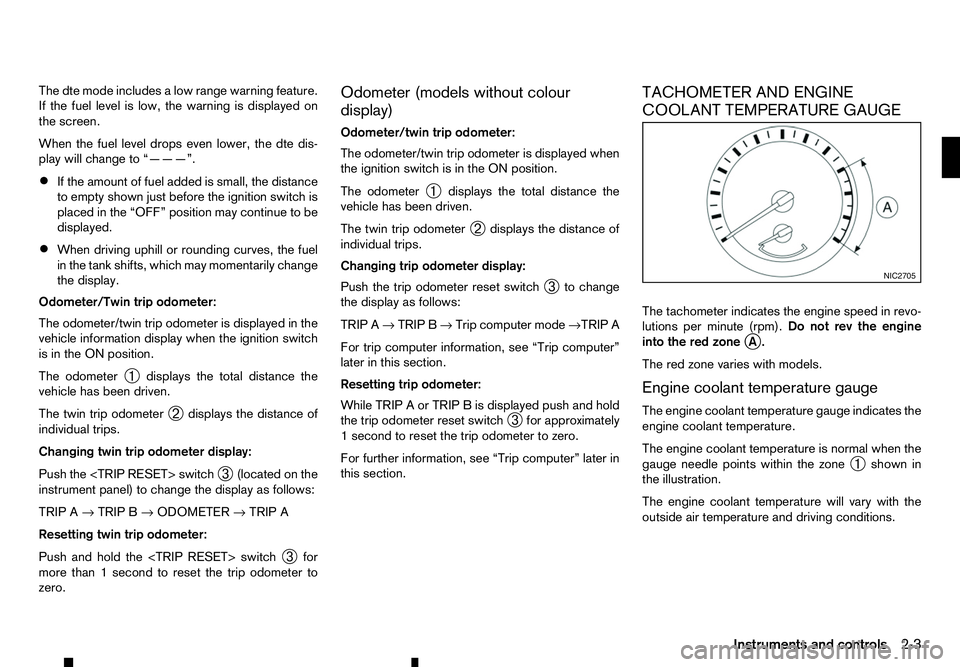
The tachometer indicates the engine speed in revo-
lutions per minute (rpm).
Do not rev the engine
into the red zone j
A.
The red zone varies with models.
Engine coolant temperature gauge
The engine coolant temperature gauge indicates the
engine coolant temperature.
The engine coolant temperature is normal when the
gauge needle points within the zone ➀shown in
the illustration.
The engine coolant temperature will vary with the
outside air temperature and driving conditions. NIC2705
Instruments and controls
2-3
Page 63 of 340
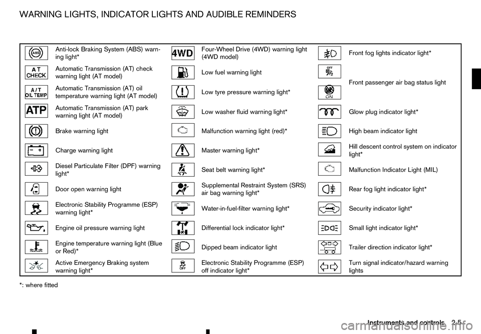
Anti-lock Braking System (ABS) warn-
ing light* Four-Wheel Drive (4WD) warning light
(4WD model) Front fog lights indicator light*
Automatic Transmission (AT) check
warning light (AT model) Low fuel warning light
Front passenger air bag status light
Automatic Transmission (AT) oil
temperature warning light (AT model) Low tyre pressure warning light*
Automatic Transmission (AT) park
warning light (AT model) Low washer fluid warning light*
Glow plug indicator light*
Brake warning light
Malfunction warning light (red)*
High beam indicator light
Charge warning light
Master warning light*
Hill descent control system on indicator
light* Diesel Particulate Filter (DPF) warning
light* Seat belt warning light*
Malfunction Indicator Light (MIL)
Door open warning light
Supplemental Restraint System (SRS)
air bag warning light* Rear fog light indicator light*
Electronic Stability Programme (ESP)
warning light* Water-in-fuel-filter warning light*
Security indicator light*
Engine oil pressure warning light
Differential lock indicator light*
Small light indicator light*
Engine temperature warning light (Blue
or Red)* Dipped beam indicator light
Trailer direction indicator light*
Active Emergency Braking system
warning light* Electronic Stability Programme (ESP)
off indicator light* Turn signal indicator/hazard warning
lights
*: where fitted WARNING LIGHTS, INDICATOR LIGHTS AND AUDIBLE REMINDERS
Instruments and controls2-5
Page 64 of 340
CHECKING LIGHTS
With all doors closed, apply the parking brake, fas-
ten the seat belts and place the ignition switch in the
ON position without starting the engine. The follow-
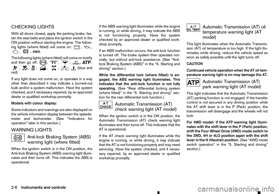
ing lights (where fitted) will come on: , ,
, , .
The following lights (where fitted) will come on briefly
and then go off: , , ,
, ,
, , , , , , (blue and
red)
If any light does not come on, or operates in away
other than described it may indicate aburned-out
bulb and/or asystem malfunction. Have the system
checked, and if necessary repaired, by an approved
dealer or qualified workshop promptly.
Models with colour display:
Some indicators and warnings are also displayed on
the vehicle information display between the speedo-
meter and tachometer. (See “Indicators for
operation” later in this section.)
WARNING LIGHTS Anti-lock Braking System (ABS)
warning light (where fitted)
When the ignition switch is in the ON position, the
Anti-lock Braking System (ABS) warning light illumi- nates and then turns off. This indicates the ABS is
operational. If the ABS warning light illuminates while the engine
is running, or while driving, it may indicate the ABS
is not functioning properly. Have the system
checked by an approved dealer or qualified work-
shop promptly.
If an ABS malfunction occurs, the anti-lock function
is turned off. The brake system then operates nor-
mally, but without anti-lock assistance. (See “Anti-
lock Braking System (ABS)” in the “5. Starting and
driving” section.)
While the differential lock (where fitted) is en-
gaged, the ABS warning light illuminates. This
indicates that the anti-lock function is not fully
operating. (See “Rear differential locking system
(where fitted)” in the “5. Starting and driving” sec-
tion for the rear differential lock function.) Automatic Transmission (AT)
check warning light (AT model)
When the ignition switch is in the ON position, the
Automatic Transmission (AT) check warning light
illuminates and then turns off. This indicates that the
AT is operational.
If the AT check warning light illuminates while the
engine is running, or while driving, it may indicate
that the AT is not functioning properly and may need
servicing. Have the system checked, and if neces-
sary repaired, by an approved dealer or qualified
workshop promptly. Automatic Transmission (AT) oil
temperature warning light (AT
model)
This light illuminates when the Automatic Transmis-
sion (AT) oil temperature is too high. If the light illu-
minates while driving, reduce the vehicle speed as
soon as safely possible until the light turns off.
CAUTION
Continued vehicle operation when the AT oil tem-
perature warning light is on may damage the AT. Automatic Transmission (AT)
park warning light (AT model)
This light indicates that the Automatic Transmission
(AT) parking function is not engaged. If the transfer
control is not secured in any driving position while
the AT shift lever is in the P(Park) position, the
transmission will disengage and the wheels will not
lock.
For 4WD model: If the ATP warning light illumi-
nates with the shift lever in the P(Park) position,
shift the Four-Wheel Drive (4WD) mode switch to
the 2WD, 4H or 4LO position again with the shift
lever in the N(Neutral) position. (See “4WD mode
switch operation” in the “5. Starting and driving”
section.)
2-6 Instruments and controls
Page 65 of 340
WARNING
If the 4WD mode indicator (see “Four-Wheel Drive
(4WD) warning light (4WD model)” later in this
section) is OFF or the ATP warning light is ON,
this indicates that the automatic transmission P
(Park) position will not function and could result
in the vehicle moving unexpectedly, causing seri-
ous personal injury or property damage. Always
set the parking brake. Brake warning light
WARNING
• If the brake fluid level is below the minimum
mark on the brake fluid reservoir, do not drive
the vehicle until the brake system has been
checked by an approved dealer or qualified
workshop.
• Even if you judge it to be safe, have your ve-
hicle towed because driving it could be dan-
gerous.
• Depressing the brake pedal without the en-
gine running and/or with
alow brake fluid
level could increase the stopping distance and
require greater pedal travel distance and ef-
fort.
The brake warning light indicates the parking brake
system operation, alow brake fluid level of the brake
system and an Anti-lock Braking System (ABS) mal-
function. Parking brake warning indicator:
When the ignition switch is placed in the ON posi-
tion, the brake warning light illuminates. When the
engine is started and the parking brake is released,
the brake warning light turns off.
If the parking brake is not fully released, the brake
warning light remains on. Be sure that the brake
warning light has turned off before driving. (See
“Parking brake” in the “3. Pre-driving checks and
adjustments” section.)
Low brake fluid warning indicator:
If the brake warning light illuminates while the en-
gine is running, or while driving, and the parking
brake is released, it may indicate the brake fluid
level is low.
When the brake warning light illuminates while driv-
ing, stop the vehicle safely as soon as possible.
Stop the engine and check the brake fluid level. If
the brake fluid level is at the minimum mark, add
brake fluid as necessary. (See “Brake fluid” in the
“8. Maintenance and do-it-yourself” section.)
If the brake fluid level is sufficient, have the brake
system checked by an approved dealer or qualified
workshop promptly.
Anti-lock Braking System (ABS) warning
indicator (where fitted):
When the parking brake is released and the brake
fluid level is sufficient, if both the brake warning light
and the Anti-lock Braking System (ABS) warning
light illuminate, it may indicate the ABS is not func-
tioning properly. Have the brake system checked, and if necessary repaired, by an approved dealer or
qualified workshop promptly. (See “Brake system”
in the “5. Starting and driving” section.) Charge warning light
When the ignition switch is in the ON position, the
charge warning light illuminates. After starting the
engine, the charge warning light turns off. This indi-
cates that the charging system is operational.
If the charge warning light illuminates while the en-
gine is running, or while driving, it may indicate that
the charging system is not functioning properly and
may need servicing.
When the charge warning light illuminates while driv-
ing, stop the vehicle safely as soon as possible.
Stop the engine and check the alternator belt. If the
alternator belt is loose, broken or missing, contact
an approved dealer or qualified workshop promptly.
(See “Drive belt” in the “8. Maintenance and
do-it-yourself” section.)
If the alternator belt appears to be functioning cor-
rectly but the charge warning light remains illumi-
nated, have the charging system checked by an
approved dealer or qualified workshop promptly.
CAUTION
Do not continue driving if the alternator belt is
loose, broken or missing.
Instruments and controls 2-7