tow RENAULT ALASKAN 2017 Owners Manual
[x] Cancel search | Manufacturer: RENAULT, Model Year: 2017, Model line: ALASKAN, Model: RENAULT ALASKAN 2017Pages: 340, PDF Size: 6.93 MB
Page 9 of 340
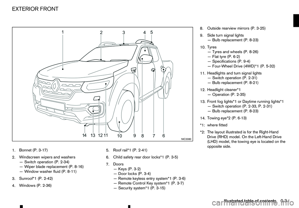
1.
Bonnet (P. 3-17)
2. Windscreen wipers and washers
—S
witch operation (P. 2-34)
—W iper blade replacement (P. 8-16)
—W indow washer fluid (P. 8-11)
3. Sunroof*1 (P. 2-42)
4. Windows (P. 2-36) 5.
Roof rail*1 (P. 2-41)
6. Child safety rear door locks*1 (P. 3-5)
7. Doors
—K
eys (P. 3-2)
—D oor locks (P. 3-4)
—R emote keyless entry system*1 (P. 3-6)
—R emote Control Key system*1 (P. 3-7)
—S ecurity system*1 (P. 3-15) 8.
Outside rearview mirrors (P. 3-25)
9. Side turn signal lights
—B
ulb replacement (P. 8-23)
10. Tyres
—T
yres and wheels (P. 8-26)
—F lat tyre (P. 6-2)
—S pecifications (P. 9-4)
—F our-Wheel Drive (4WD)*1 (P. 5-32)
11. Headlights and turn signal lights
—S
witch operation (P. 2-31)
—B ulb replacement (P. 8-21)
12. Headlight cleaner*1
—O
peration (P. 2-35)
13. Front fog lights*1 or Daytime running lights*1
—S
witch operation (P. 2-33, P. 2-31)
—B ulb replacement (P. 8-23)
14. Towing eye*2 (P. 6-13)
*1: where fitted
*2: The layout illustrated is for the Right-Hand
Drive (RHD) model. On the Left-Hand Drive
(LHD) model, the towing eye is located on the
opposite side. NIC3080
EXTERIOR FRONT
Illustrated table of contents0-3
Page 30 of 340
THREE-POINT TYPE SEAT BELTS
Fastening seat belts WARNING
The seatback should not be in
areclined position
any more than needed for comfort. Seat belts are
most effective when the passenger sits well back
and straight up in the seat.
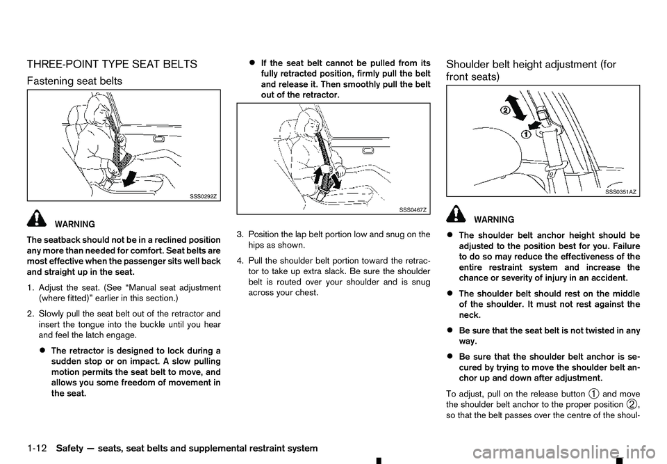
1. Adjust the seat. (See “Manual seat adjustment
(where fitted)” earlier in this section.)
2. Slowly pull the seat belt out of the retractor and insert the tongue into the buckle until you hear
and feel the latch engage.
• The retractor is designed to lock during a
sudden stop or on impact.
Aslow pulling
motion permits the seat belt to move, and
allows you some freedom of movement in
the seat. •
If the seat belt cannot be pulled from its
fully retracted position, firmly pull the belt
and release it. Then smoothly pull the belt
out of the retractor.
3. Position the lap belt portion low and snug on the hips as shown.
4. Pull the shoulder belt portion toward the retrac- tor to take up extra slack. Be sure the shoulder
belt is routed over your shoulder and is snug
across your chest. Shoulder belt height adjustment (for
front seats) WARNING
• The shoulder belt anchor height should be
adjusted to the position best for you. Failure
to do so may reduce the effectiveness of the
entire restraint system and increase the
chance or severity of injury in an accident.
• The shoulder belt should rest on the middle
of the shoulder. It must not rest against the
neck.
• Be sure that the seat belt is not twisted in any
way.
• Be sure that the shoulder belt anchor is se-
cured by trying to move the shoulder belt an-
chor up and down after adjustment.
To adjust, pull on the release button ➀and move
the shoulder belt anchor to the proper position ➁,
so that the belt passes over the centre of the shoul- SSS0292Z
SSS0467Z SSS0351AZ
1-12 Safety —seats, seat belts and supplemental restraint system
Page 65 of 340
WARNING
If the 4WD mode indicator (see “Four-Wheel Drive
(4WD) warning light (4WD model)” later in this
section) is OFF or the ATP warning light is ON,
this indicates that the automatic transmission P
(Park) position will not function and could result
in the vehicle moving unexpectedly, causing seri-
ous personal injury or property damage. Always
set the parking brake. Brake warning light
WARNING
• If the brake fluid level is below the minimum
mark on the brake fluid reservoir, do not drive
the vehicle until the brake system has been
checked by an approved dealer or qualified
workshop.
• Even if you judge it to be safe, have your ve-
hicle towed because driving it could be dan-
gerous.
• Depressing the brake pedal without the en-
gine running and/or with
alow brake fluid
level could increase the stopping distance and
require greater pedal travel distance and ef-
fort.
The brake warning light indicates the parking brake
system operation, alow brake fluid level of the brake
system and an Anti-lock Braking System (ABS) mal-
function. Parking brake warning indicator:
When the ignition switch is placed in the ON posi-
tion, the brake warning light illuminates. When the
engine is started and the parking brake is released,
the brake warning light turns off.
If the parking brake is not fully released, the brake
warning light remains on. Be sure that the brake
warning light has turned off before driving. (See
“Parking brake” in the “3. Pre-driving checks and
adjustments” section.)
Low brake fluid warning indicator:
If the brake warning light illuminates while the en-
gine is running, or while driving, and the parking
brake is released, it may indicate the brake fluid
level is low.
When the brake warning light illuminates while driv-
ing, stop the vehicle safely as soon as possible.
Stop the engine and check the brake fluid level. If
the brake fluid level is at the minimum mark, add
brake fluid as necessary. (See “Brake fluid” in the
“8. Maintenance and do-it-yourself” section.)
If the brake fluid level is sufficient, have the brake
system checked by an approved dealer or qualified
workshop promptly.
Anti-lock Braking System (ABS) warning
indicator (where fitted):
When the parking brake is released and the brake
fluid level is sufficient, if both the brake warning light
and the Anti-lock Braking System (ABS) warning
light illuminate, it may indicate the ABS is not func-
tioning properly. Have the brake system checked, and if necessary repaired, by an approved dealer or
qualified workshop promptly. (See “Brake system”
in the “5. Starting and driving” section.) Charge warning light
When the ignition switch is in the ON position, the
charge warning light illuminates. After starting the
engine, the charge warning light turns off. This indi-
cates that the charging system is operational.
If the charge warning light illuminates while the en-
gine is running, or while driving, it may indicate that
the charging system is not functioning properly and
may need servicing.
When the charge warning light illuminates while driv-
ing, stop the vehicle safely as soon as possible.
Stop the engine and check the alternator belt. If the
alternator belt is loose, broken or missing, contact
an approved dealer or qualified workshop promptly.
(See “Drive belt” in the “8. Maintenance and
do-it-yourself” section.)
If the alternator belt appears to be functioning cor-
rectly but the charge warning light remains illumi-
nated, have the charging system checked by an
approved dealer or qualified workshop promptly.
CAUTION
Do not continue driving if the alternator belt is
loose, broken or missing.
Instruments and controls 2-7
Page 66 of 340
Diesel Particulate Filter (DPF)
warning light (where fitted)
When the DPF warning light illuminates, it indicates
that particulate matter is accumulated to the speci- fied amount of the limit in the filter and the filter
needs to regenerate. For filter regeneration details,
see “Diesel Particulate Filter (DPF) (where fitted)” in
the “5. Starting and driving” section.
CAUTION
If you continue driving with the DPF warning light
on without performing the filter regeneration, this
will lead to particulate matter overload in the fil-
ter.
If this occurs, then the Malfunction Indicator Light
(MIL) will turn on. The performance of the engine
might be limited to protect the DPF system. See
an approved dealer or qualified workshop to per-
form the service regeneration. Door open warning light
When the ignition switch is in the ON position, the
door open warning light illuminates if any of the doors
are open or not closed securely. Electronic Stability Programme
(ESP) warning light (where fitted)
When the ignition switch is in the ON position, the
Electronic Stability Programme (ESP) warning light illuminates and then turns off. The warning light blinks when the ESP system is
operating.
When the warning light blinks while driving, the driv-
ing condition is slippery and the vehicle’s traction
limit is about to be exceeded.
If the ESP warning light illuminates while the engine
is running or while driving, it may indicate that the
ESP system is not functioning properly and may
need servicing. Have the system checked, and if
necessary repaired, by an approved dealer or quali-
fied workshop promptly. If amalfunction occurs, the
ESP function is turned off, but the vehicle is still driv-
able. (See “Electronic Stability Programme (ESP)
system (where fitted)” in the “5. Starting and driving”
section.) Engine oil pressure warning light
When the ignition switch is in the ON position, the
engine oil pressure warning light illuminates. After
starting the engine, the engine oil pressure warning
light turns off. This indicates that the oil pressure
sensors in the engine are operational.
If the engine oil pressure warning light illuminates or
blinks while the engine is running, it may indicate
that the engine oil pressure is low.
Stop the vehicle safely as soon as possible. Stop
the engine immediately and call an approved dealer
or qualified workshop. CAUTION
• Running the engine with the engine oil pres-
sure warning light illuminated could cause se-
rious damage to the engine.
• The engine oil pressure warning light is not
designed to indicate
alow oil level. The oil
level should be checked using the dipstick.
(See “Checking engine oil level” in the
“8. Maintenance and do-it-yourself” section.) Engine temperature warning
light (red/blue) (where fitted)
High temperature indicator light (Red):
The red warning light comes on when the engine
overheats. WARNING
If the high temperature warning light illuminates
while the engine is running, it may indicate the
engine temperature is extremely high. Stop the
vehicle safely as soon as possible. If the vehicle
is overheated, continuing vehicle operation may
seriously damage the engine.
• If the engine coolant temperature warning
light (RED) comes on while driving, stop the
vehicle as soon as possible and contact an
approved dealer or qualified workshop.
• When towing
atrailer or driving uphill, reduce
the vehicle speed as soon as safely possible
to decrease the engine coolant temperature.
2-8 Instruments and controls
Page 69 of 340
•
When
aspare tyre is mounted or
awheel is
replaced, the TPMS will not function and the
low tyre pressure warning light will flash for
approximately 1minute. The light will remain
on after 1minute. Contact an approved dealer
or qualified workshop as soon as possible for
tyre replacement and/or system resetting.
• Replacing tyres with those not originally speci-
fied by RENAULT could affect the proper op-
eration of the TPMS.
CAUTION
• The TPMS is not
asubstitute for the regular
tyre pressure check. Be sure to check the tyre
pressure regularly.
• If the vehicle is being driven at speeds of less
than 25 km/h (16 MPH), the TPMS may not
operate correctly.
• Be sure to install the specified size of tyres to
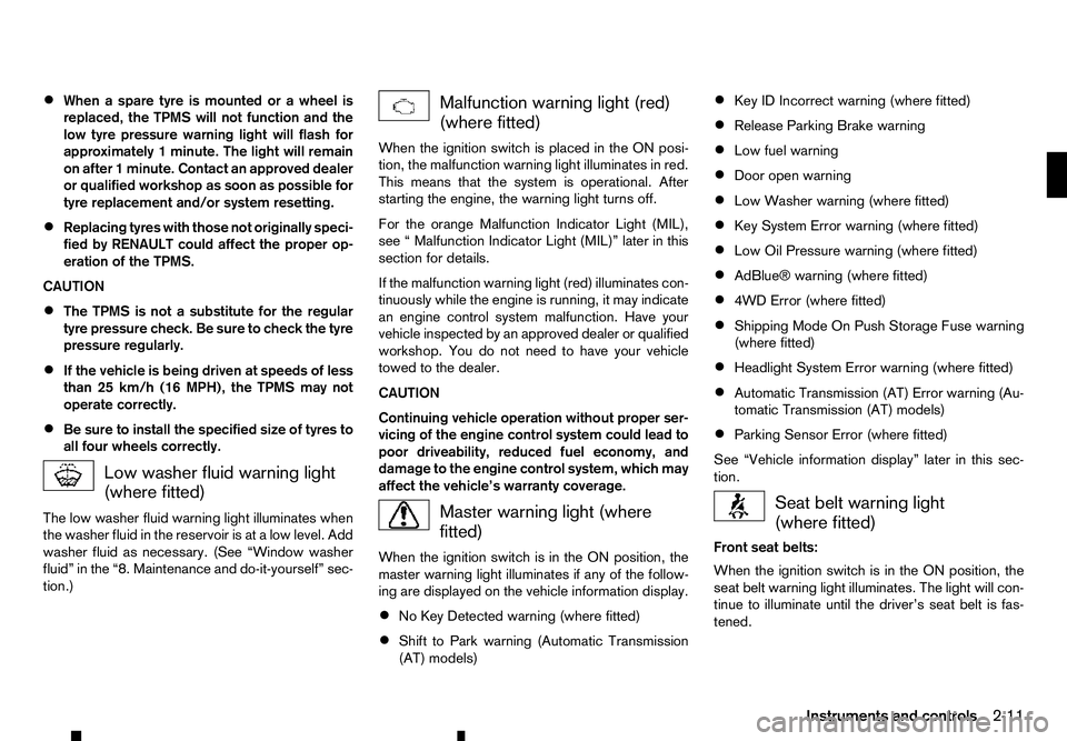
all four wheels correctly. Low washer fluid warning light
(where fitted)
The low washer fluid warning light illuminates when
the washer fluid in the reservoir is at alow level. Add
washer fluid as necessary. (See “Window washer
fluid” in the “8. Maintenance and do-it-yourself” sec-
tion.) Malfunction warning light (red)
(where fitted)
When the ignition switch is placed in the ON posi-
tion, the malfunction warning light illuminates in red.
This means that the system is operational. After
starting the engine, the warning light turns off.
For the orange Malfunction Indicator Light (MIL),
see “Malfunction Indicator Light (MIL)” later in this
section for details.
If the malfunction warning light (red) illuminates con-
tinuously while the engine is running, it may indicate
an engine control system malfunction. Have your
vehicle inspected by an approved dealer or qualified
workshop. You do not need to have your vehicle
towed to the dealer.
CAUTION
Continuing vehicle operation without proper ser-
vicing of the engine control system could lead to
poor driveability, reduced fuel economy, and
damage to the engine control system, which may
affect the vehicle’s warranty coverage. Master warning light (where
fitted)
When the ignition switch is in the ON position, the
master warning light illuminates if any of the follow-
ing are displayed on the vehicle information display.
• No Key Detected warning (where fitted)
• Shift to Park warning (Automatic Transmission
(AT) models) •
Key ID Incorrect warning (where fitted)
• Release Parking Brake warning
• Low fuel warning
• Door open warning
• Low Washer warning (where fitted)
• Key System Error warning (where fitted)
• Low Oil Pressure warning (where fitted)
• AdBlue® warning (where fitted)
• 4WD Error (where fitted)
• Shipping Mode On Push Storage Fuse warning
(where fitted)
• Headlight System Error warning (where fitted)
• Automatic Transmission (AT) Error warning (Au-
tomatic Transmission (AT) models)
• Parking Sensor Error (where fitted)
See “Vehicle information display” later in this sec-
tion. Seat belt warning light
(where fitted)
Front seat belts:
When the ignition switch is in the ON position, the
seat belt warning light illuminates. The light will con-
tinue to illuminate until the driver’s seat belt is fas-
tened.
Instruments and controls 2-11
Page 71 of 340
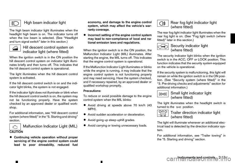
High beam indicator light
The high beam indicator light illuminates when the
headlight high beam is on. The indicator turns off
when the low beam is selected. (See “Headlight
and turn signal switch” later in this section.) Hill descent control system on
indicator light (where fitted)
When the ignition switch is in the ON position the hill descent control system on indicator light illumi-
nates briefly and then turns off. This indicates that
the hill descent control system is operational.
The light illuminates when the hill descent control
system is activated.
If the hill descent control switch is on and the indi-
cator light blinks, the system is not engaged.
If the indicator light does not illuminate or blink when
the hill descent control switch is on, the system may
not be functioning properly. Have the system
checked by an approved dealer or qualified work-
shop.
For additional information, see “Hill descent control
system (where fitted)” in the “5. Starting and driving”
section. Malfunction Indicator Light (MIL)
CAUTION
• Continuing vehicle operation without proper
servicing of the engine control system could
lead to poor driveability, reduced fuel economy, and damage to the engine control
system, which may affect the vehicle’s war-
ranty coverage.
• Incorrect setting of the engine control system
may lead to non-compliance of local and na-
tional emission laws and regulations.
When the ignition switch is in the ON position, the
Malfunction Indicator Light (MIL) illuminates. After
starting the engine, the MIL turns off. This indicates
that the engine control system is operational.
If the Malfunction Indicator Light illuminates or blinks
while the engine is running, it may indicate that the
engine control system is not functioning properly
and may need servicing. Have the system checked,
and if necessary repaired, by an approved dealer or
qualified workshop promptly.
Precautions:
To reduce or avoid possible damage to the engine
control system when the MIL blinks: • Avoid driving at speeds above 70 km/h (43
MPH).
• Avoid sudden acceleration or deceleration.
• Avoid going up steep uphill grades.
• Avoid carrying or towing unnecessary loads. Rear fog light indicator light
(where fitted)
The rear fog light indicator light illuminates when the
rear fog light is on. (See “Fog light switch (where
fitted)” later in this section.) Security indicator light
(where fitted)
The security indicator light blinks when the ignition
switch is in the ACC, OFF or LOCK position. This
function indicates that the security system equipped
on the vehicle is operational.
If the security system is malfunctioning, this light will
remain on while the ignition switch is in the ON posi- tion. (See “Security system (where fitted)” in the
“3. Pre-driving checks and adjustments” section for
additional information.) Small light indicator light
(where fitted)
The light illuminates when the headlight switch is
turned to the position.
Trailer direction indicator light
(where fitted)
The light will illuminate whenever an additional elec-
trical load is detected by the direction indicator sys-
tem.
For additional information, see “Trailer towing” in
the “5. Starting and driving” section.
Instruments and controls 2-13
Page 89 of 340
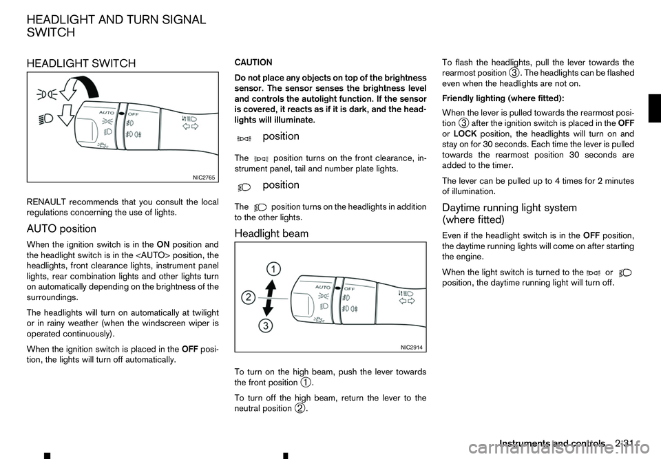
HEADLIGHT SWITCH
RENAULT recommends that you consult the local
regulations concerning the use of lights.
AUTO position
When the ignition switch is in the ONposition and
the headlight switch is in the
headlights, front clearance lights, instrument panel
lights, rear combination lights and other lights turn
on automatically depending on the brightness of the
surroundings.
The headlights will turn on automatically at twilight
or in rainy weather (when the windscreen wiper is
operated continuously).
When the ignition switch is placed in the OFFposi-
tion, the lights will turn off automatically. CAUTION
Do not place any objects on top of the brightness
sensor. The sensor senses the brightness level
and controls the autolight function. If the sensor
is covered, it reacts as if it is dark, and the head-
lights will illuminate.
m position
The position
turns on the front clearance, in-
strument panel, tail and number plate lights.
m position
The position
turns on the headlights in addition
to the other lights.
Headlight beam
To turn on the high beam, push the lever towards
the front position ➀.
To turn off the high beam, return the lever to the
neutral position ➁. To flash the headlights, pull the lever towards the
rearmost position
➂.T
he headlights can be flashed
even when the headlights are not on.
Friendly lighting (where fitted):
When the lever is pulled towards the rearmost posi-
tion ➂after the ignition switch is placed in the
OFF
or LOCK position, the headlights will turn on and
stay on for 30 seconds. Each time the lever is pulled
towards the rearmost position 30 seconds are
added to the timer.
The lever can be pulled up to 4times for 2minutes
of illumination.
Daytime running light system
(where fitted)
Even if the headlight switch is in the OFFposition,
the daytime running lights will come on after starting
the engine.
When the light switch is turned to the or
position, the daytime running light will turn off.NIC2765
NIC2914
HEADLIGHT AND TURN SIGNAL
SWITCH
Instruments and controls2-31
Page 92 of 340
WARNING
In freezing temperatures, the washer fluid may
freeze on the windscreen and obscure your vi-
sion. Warm the windscreen with the defogger be-
fore you wash the windscreen.
CAUTION
• Do not operate the washer continuously for
longer than 30 seconds.
• Do not operate the washer if the window
washer fluid reservoir is empty.
• If the wiper operation is interrupted by snow
or ice, the wiper may stop moving to protect
its motor. If this occurs, turn the wiper switch
to the OFF position and remove the snow or
ice on and around the wiper arms. In approxi-
mately
1minute, turn the switch on again to
operate the wiper.
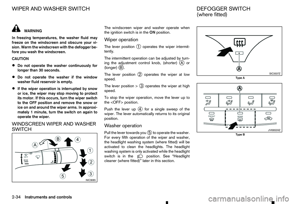
WINDSCREEN WIPER AND WASHER
SWITCH The windscreen wiper and washer operate when
the ignition switch is in the
ONposition.
Wiper operation
The lever position ➀operates the wiper intermit-
tently.
The intermittent operation can be adjusted by turn-
ing the adjustment control knob, (shorter) j
Aor
(longer) j
B.
The lever position ➁operates the wiper at low
speed.
The lever position > ➂operates the wiper at high
speed.
To stop the wiper operation, move the lever up to
the
Push the lever up ➃for
asingle sweep of the
wiper. The lever automatically returns to its original
position.
Washer operation
Pull the lever towards you ➄to operate the washer.
For every fifth operation of the wiper and washer,
the headlight washing system (where fitted) will be
activated to clean the headlights. The headlight
washing system is only activated while the headlight
switch is in the position. See “Headlight
cleaner (where fitted)” later in this section. NIC3085 SIC3537Z
Type A
JVI0853XZ
Type B
WIPER AND WASHER SWITCH
DEFOGGER SWITCH
(where fitted)
2-34 Instruments and controls
Page 93 of 340
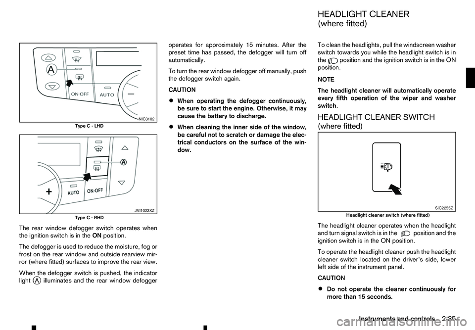
The rear window defogger switch operates when
the ignition switch is in the ONposition.
The defogger is used to reduce the moisture, fog or
frost on the rear window and outside rearview mir-
ror (where fitted) surfaces to improve the rear view.
When the defogger switch is pushed, the indicator
light j
Ai lluminates and the rear window defogger operates for approximately 15 minutes. After the
preset time has passed, the defogger will turn off
automatically.
To turn the rear window defogger off manually, push
the defogger switch again.
CAUTION
• When operating the defogger continuously,
be sure to start the engine. Otherwise, it may
cause the battery to discharge.
• When cleaning the inner side of the window,
be careful not to scratch or damage the elec-
trical conductors on the surface of the win-
dow. To clean the headlights, pull the windscreen washer
switch towards you while the headlight switch is in
the position and the ignition switch is in the ON
position.
NOTE
The headlight cleaner will automatically operate
every fifth operation of the wiper and washer
switch.
HEADLIGHT CLEANER SWITCH
(where fitted)
The headlight cleaner operates when the headlight
and turn signal switch is in the position and the
ignition switch is in the ON position.
To operate the headlight cleaner push the headlight
cleaner switch located on the driver’s side, lower
left side of the instrument panel.
CAUTION
• Do not operate the cleaner continuously for
more than 15 seconds. NIC3102
Type C-LHD JVI1022XZ
Type C-RHD SIC2255Z
Headlight cleaner switch (where fitted)
HEADLIGHT CLEANER
(where fitted)
Instruments and controls 2-35
Page 112 of 340
The Remote Control Key is always communicating
with the vehicle as it receives radio waves. The Re-
mote Control Key system transmits weak radio
waves. Environmental conditions may interfere with
the operation of the Remote Control Key system
under the following operating conditions.
• When operating near
alocation where strong
radio waves are transmitted, such as aTVtower,
power station and broadcasting station.
• When in possession of wireless equipment, such
as am obile telephone, transceiver, and CB ra-
dio.
• When the Remote Control Key is in contact with
or covered by metallic materials.
• When any type of radio wave remote control is
used nearby.
• When the Remote Control Key is placed near an
electric appliance such as
apersonal computer.
In such cases, correct the operating conditions be-
fore using the Remote Control Key function or use
the mechanical key.
Although the life of the battery varies depending on
the operating conditions, the battery’s life is approxi-
mately 2years. If the battery is discharged, replace
it with anew one.
For information regarding replacement of abattery,
see “Remote Control Key battery replacement” in
the “8. Maintenance and do-it-yourself” section.
Since the Remote Control Key is continuously re-
ceiving radio waves, if the key is left near equipment which transmits strong radio waves, such as signals
from
aTVa nd personal computer, the battery life
may become shorter.
Because the steering wheel is locked electrically,
unlocking the steering wheel with the ignition switch
in the LOCK position is impossible when the vehicle
battery is completely discharged. Pay special atten-
tion that the vehicle battery is not completely dis-
charged.
As many as 4Remote Control Keys can be regis-
tered and used with one vehicle. For information
about the purchase and use of additional Remote
Control Keys, contact an approved dealer or quali-
fied workshop.
CAUTION
• Do not allow the Remote Control Key, which
contains electrical components, to come into
contact with water or salt water. This could
affect the system function.
• Do not drop the Remote Control Key.
• Do not strike the Remote Control Key sharply
against another object.
• Do not change or modify the Remote Control
Key.
• Wetting may damage the Remote Control Key.
If the Remote Control Key gets wet, immedi-
ately wipe until it is completely dry.
• If the outside temperature is below −10°C
(14°F), the battery of the Remote Control Key
may not function properly. •
Do not place the Remote Control Key for an
extended period in an area where tempera-
tures exceed 60°C (140°F).
• Do not attach the Remote Control Key to a
key holder that contains
amagnet.
• Do not place the Remote Control Key near
equipment that produces
amagnetic field,
such as aTV, audio equipment and personal
computers.
If an Remote Control Key is lost or stolen, RENAULT
recommends erasing the ID code of that Remote
Control Key from the vehicle. This may prevent the
unauthorised use of the Remote Control Key to op-
erate the vehicle. For information regarding the eras-
ing procedure, contact an approved dealer or quali-
fied workshop.
The Remote Control Key function can be disabled.
For information about disabling the Remote Control
Key function, contact an approved dealer or quali-
fied workshop.
3-8 Pre-driving checks and adjustments