RENAULT CAPTUR 2014 1.G Repair Manual
Manufacturer: RENAULT, Model Year: 2014, Model line: CAPTUR, Model: RENAULT CAPTUR 2014 1.GPages: 244, PDF Size: 5.64 MB
Page 61 of 244
1.55
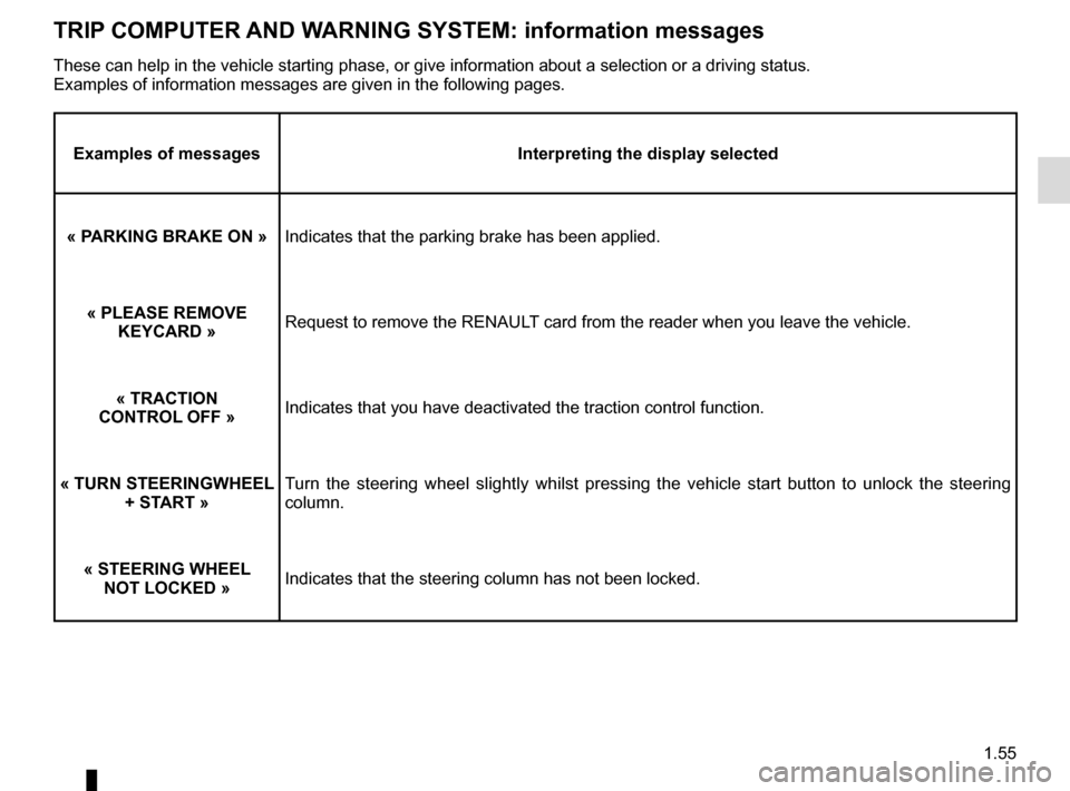
TRIP COMPUTER AND WARNING SYSTEM: information messages
Examples of messagesInterpreting the display selected
« PARKING BRAKE ON » Indicates that the parking brake has been applied.
« PLEASE REMOVE KEYCARD » Request to remove the RENAULT card from the reader when you leave the vehicle.
« TRACTION
CONTROL OFF » Indicates that you have deactivated the traction control function.
« TURN STEERINGWHEEL + START » Turn the steering wheel slightly whilst pressing the vehicle start button\
to unlock the steering
column.
« STEERING WHEEL NOT LOCKED » Indicates that the steering column has not been locked.
These can help in the vehicle starting phase, or give information about \
a selection or a driving status.
Examples of information messages are given in the following pages.
Page 62 of 244
1.56
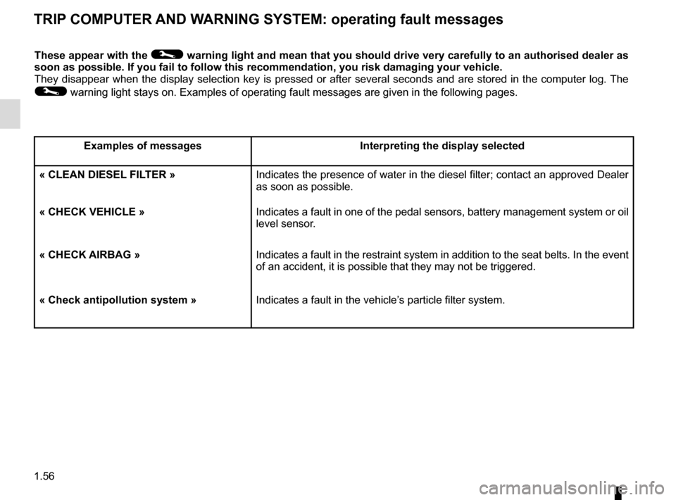
TRIP COMPUTER AND WARNING SYSTEM: operating fault messages
These appear with the © warning light and mean that you should drive very carefully to an author\
ised dealer as
soon as possible. If you fail to follow this recommendation, you risk da\
maging your vehicle.
They disappear when the display selection key is pressed or after severa\
l seconds and are stored in the computer log. The
© warning light stays on. Examples of operating fault messages are given \
in the following pages.
Examples of messages Interpreting the display selected
« CLEAN DIESEL FILTER » Indicates the presence of water in the diesel filter; contact an approve\
d Dealer
as soon as possible.
« CHECK VEHICLE » Indicates a fault in one of the pedal sensors, battery management system\
or oil
level sensor.
« CHECK AIRBAG » Indicates a fault in the restraint system in addition to the seat belts.\
In the event
of an accident, it is possible that they may not be triggered.
« Check antipollution system » Indicates a fault in the vehicle’s particle filter system.
Page 63 of 244
1.57
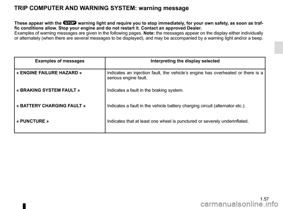
TRIP COMPUTER AND WARNING SYSTEM: warning message
These appear with the ® warning light and require you to stop immediately, for your own safety, as soon as traf-
fic conditions allow. Stop your engine and do not restart it. Contact an approved Dealer.
Examples of warning messages are given in the following pages. Note: the messages appear on the display either individually
or alternately (when there are several messages to be displayed), and \
may be accompanied by a warning light and/or a beep.
Examples of messages Interpreting the display selected
« ENGINE FAILURE HAZARD » Indicates an injection fault, the vehicle’s engine has overheated or there is a
serious engine fault.
« BRAKING SYSTEM FAULT » Indicates a fault in the braking system.
« BATTERY CHARGING FAULT » Indicates a fault in the vehicle battery charging circuit (alternator e\
tc.).
« PUNCTURE » Indicates that at least one wheel is punctured or severely underinflated\
.
Page 64 of 244
1.58
Power Assisted Steering
Never drive with an inadequately
charged battery.
Variable power assisted
steering
The variable power assisted steering
system is equipped with an electronic
control system which alters the level of
assistance to suit the vehicle speed.
Steering is made easier during parking
manoeuvres (for added comfort) whilst
the force needed to steer increases
progressively as the speed rises (for
enhanced safety at high speeds).
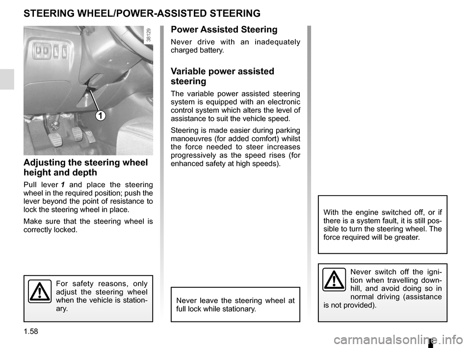
Adjusting the steering wheel
height and depth
Pull lever 1 and place the steering
wheel in the required position; push the
lever beyond the point of resistance to
lock the steering wheel in place.
Make sure that the steering wheel is
correctly locked.
For safety reasons, only
adjust the steering wheel
when the vehicle is station-
ary.
STEERING WHEEL/POWER-ASSISTED STEERING
1
Never switch off the igni-
tion when travelling down-
hill, and avoid doing so in
normal driving (assistance
is not provided).
With the engine switched off, or if
there is a system fault, it is still pos-
sible to turn the steering wheel. The
force required will be greater.
Never leave the steering wheel at
full lock while stationary.
Page 65 of 244

1.59
Wait a few seconds, the minutes will
flash: repeatedly press or press and
hold button 3 or 4 to set the time.
When setting is complete, the hours
and minutes remain displayed continu-
ously for 2 seconds: your setting is reg-
istered.
You may change the display.Display A
To access the display 2 for setting the
time, press button 3 or 4 on the stalk 1.
Wait a few seconds; the hours and min-
utes will begin to flash. You are now in
setting mode, press and hold button 3
or 4 to set the hour.
Once the minutes flash, repeatedly
press or press and hold button 3 ou 4
to set the time.
CLOCK AND EXTERIOR TEMPERATURE (1/2)
3
4
If the power supply is cut (battery
disconnected, supply wire cut, etc.),
the clock must be reset.
We recommend that you do not
adjust these settings while driving.
9°C 12:00
2
A
1
1
Page 66 of 244
1.60
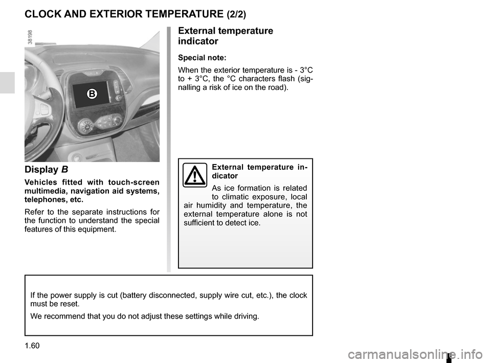
Display B
Vehicles fitted with touch-screen
multimedia, navigation aid systems,
telephones, etc.
Refer to the separate instructions for
the function to understand the special
features of this equipment.
External temperature
indicator
Special note:
When the exterior temperature is - 3°C
to + 3°C, the °C characters flash (sig-
nalling a risk of ice on the road).
External temperature in-
dicator
As ice formation is related
to climatic exposure, local
air humidity and temperature, the
external temperature alone is not
sufficient to detect ice.
CLOCK AND EXTERIOR TEMPERATURE (2/2)
If the power supply is cut (battery disconnected, supply wire cut, etc.\
), the clock
must be reset.
We recommend that you do not adjust these settings while driving.
B
Page 67 of 244
1.61
Heated door mirrorsWith the engine running, mirror de-
icing is activated simultaneously with
rear screen de-icing/demisting.
Folding door mirrors
(depending on vehicle)
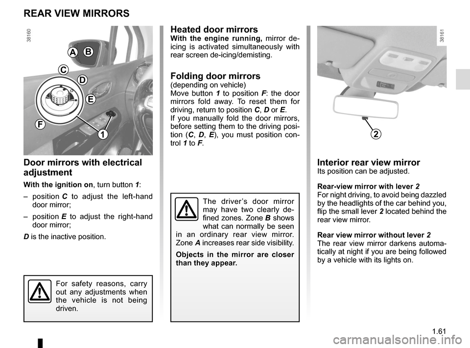
Move button 1 to position F: the door
mirrors fold away. To reset them for
driving, return to position C, D or E.
If you manually fold the door mirrors,
before setting them to the driving posi-
tion (C , D , E ), you must position con-
trol 1 to F.
The driver’s door mirror
may have two clearly de-
fined zones. Zone B shows
what can normally be seen
in an ordinary rear view mirror.
Zone A increases rear side visibility.
Objects in the mirror are closer
than they appear.
Door mirrors with electrical
adjustment
With the ignition on , turn button 1:
– position C to adjust the left-hand
door mirror;
– position E to adjust the right-hand
door mirror;
D is the inactive position.
REAR VIEW MIRRORS
AB
D
C
E
For safety reasons, carry
out any adjustments when
the vehicle is not being
driven.
Interior rear view mirrorIts position can be adjusted.
Rear-view mirror with lever 2
For night driving, to avoid being dazzled
by the headlights of the car behind you,
flip the small lever 2 located behind the
rear view mirror.
Rear view mirror without lever 2
The rear view mirror darkens automa-
tically at night if you are being followed
by a vehicle with its lights on.
F
21
Page 68 of 244
1.62
Daytime running lights
function
(front lights only)
Depending on the vehicle, daytime run-
ning lights come on automatically when
the engine is started.
EXTERIOR LIGHTING AND SIGNALS (1/3)
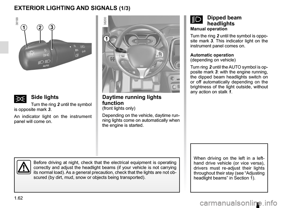
šSide lights
Turn the ring 2 until the symbol
is opposite mark 3.
An indicator light on the instrument
panel will come on.
1
Before driving at night, check that the electrical equipment is operatin\
g
correctly and adjust the headlight beams (if your vehicle is not carryi\
ng
its normal load). As a general precaution, check that the lights are not ob-
scured (by dirt, mud, snow or objects being transported).
kDipped beam
headlights
Manual operation
Turn the ring 2 until the symbol is oppo-
site mark 3. This indicator light on the
instrument panel comes on.
Automatic operation
(depending on vehicle)
Turn ring 2 until the AUTO symbol is op-
posite mark 3: with the engine running,
the dipped beam headlights switch on
or off automatically depending on the
brightness of the light outside, without
any action on stalk 1.
When driving on the left in a left-
hand drive vehicle (or vice versa),
drivers must re-adjust their lights
throughout their stay (see “Adjusting
headlight beams” in Section 1).
312
Page 69 of 244
1.63
EXTERIOR LIGHTING AND SIGNALS (2/3)
Switching off the lights
There are two possibilities:
– manually, move ring 2 to position 0;
– the lights will go out automatically when the engine is switched off, the
driver’s door is opened or the vehicle
is locked. In this case, the next time
the engine is started, the lights will
be switched back on according to the
position of the ring 2, taking into ac-
count the exterior light level, without
moving the stalk 1.
Lights-on reminder buzzer
When the lights have been left on after
turning the engine off, a warning beep
will sound when the driver’s door is
opened to remind you that the lights
are still on.
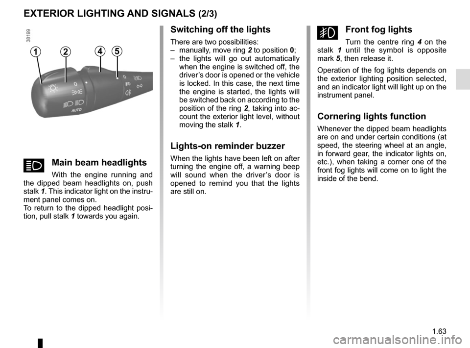
gFront fog lights
Turn the centre ring 4 on the
stalk 1 until the symbol is opposite
mark 5, then release it.
Operation of the fog lights depends on
the exterior lighting position selected,
and an indicator light will light up on the
instrument panel.
Cornering lights function
Whenever the dipped beam headlights
are on and under certain conditions (at
speed, the steering wheel at an angle,
in forward gear, the indicator lights on,
etc.), when taking a corner one of the
front fog lights will come on to light the
inside of the bend.
12
áMain beam headlights
With the engine running and
the dipped beam headlights on, push
stalk 1. This indicator light on the instru-
ment panel comes on.
To return to the dipped headlight posi-
tion, pull stalk 1 towards you again.
45
Page 70 of 244
1.64
EXTERIOR LIGHTING AND SIGNALS (3/3)
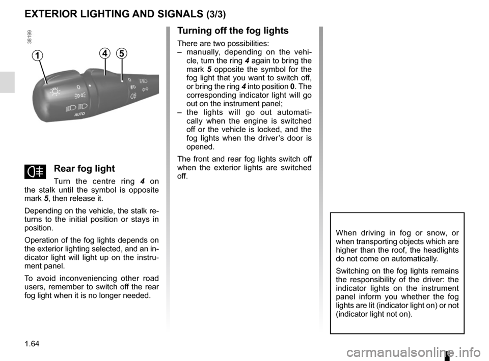
fRear fog light
Turn the centre ring 4 on
the stalk until the symbol is opposite
mark 5, then release it.
Depending on the vehicle, the stalk re-
turns to the initial position or stays in
position.
Operation of the fog lights depends on
the exterior lighting selected, and an in-
dicator light will light up on the instru-
ment panel.
To avoid inconveniencing other road
users, remember to switch off the rear
fog light when it is no longer needed.
Turning off the fog lights
There are two possibilities:
– manually, depending on the vehi- cle, turn the ring 4 again to bring the
mark 5 opposite the symbol for the
fog light that you want to switch off,
or bring the ring 4 into position 0. The
corresponding indicator light will go
out on the instrument panel;
– the lights will go out automati- cally when the engine is switched
off or the vehicle is locked, and the
fog lights when the driver’s door is
opened.
The front and rear fog lights switch off
when the exterior lights are switched
off.
When driving in fog or snow, or
when transporting objects which are
higher than the roof, the headlights
do not come on automatically.
Switching on the fog lights remains
the responsibility of the driver: the
indicator lights on the instrument
panel inform you whether the fog
lights are lit (indicator light on) or not
(indicator light not on).
415