Button 2 RENAULT CAPTUR 2017 1.G Owner's Guide
[x] Cancel search | Manufacturer: RENAULT, Model Year: 2017, Model line: CAPTUR, Model: RENAULT CAPTUR 2017 1.GPages: 248, PDF Size: 6.56 MB
Page 95 of 248
2.13
DRIVING ADVICE, ECO DRIVING (1/5)
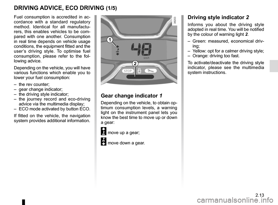
Driving style indicator 2
Informs you about the driving style
adopted in real time. You will be notified
by the colour of warning light 2.
– Green: measured, economical driv- ing;
– Yellow: opt for a calmer driving style;
– Orange: driving too fast.
To activate/deactivate the driving style
indicator, please see the multimedia
system instructions.
1
2
Gear change indicator 1
Depending on the vehicle, to obtain op-
timum consumption levels, a warning
light on the instrument panel lets you
know the best time to move up or down
a gear:
Š move up a gear;
‰ move down a gear.
Fuel consumption is accredited in ac-
cordance with a standard regulatory
method. Identical for all manufactu-
rers, this enables vehicles to be com-
pared with one another. Consumption
in real time depends on vehicle usage
conditions, the equipment fitted and the
user’s driving style. To optimise fuel
consumption, please refer to the fol-
lowing advice.
Depending on the vehicle, you will have
various functions which enable you to
lower your fuel consumption:
– the rev counter;
– gear change indicator;
– the driving style indicator;
– the journey record and eco-driving
advice via the multimedia display;
– ECO mode activated by button ECO.
If fitted on the vehicle, the navigation
system provides additional information.
Page 104 of 248
2.22
SYSTEM A (cntd.)
Resetting the standard level for the
tyre pressures
This should be done:
– after each reinflation or readjustment of the pressure of one of the tyres;
– when the standard tyre pressure needs to be changed to adapt to
usage conditions (empty, carrying a
load, motorway driving, etc.);
– after changing a wheel;
– after using the tyre inflation kit;
2
3
4
– after swapping a wheel (however, this practice is not recommended).
It should always be done after checking
the tyre pressure of all four tyres when
cold.
Tyre pressures must correspond to the
current usage of the vehicle (empty,
carrying a load, motorway driving, etc.).
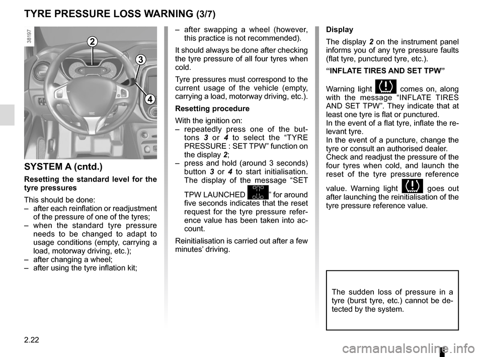
Resetting procedure
With the ignition on:
– repeatedly press one of the but- tons 3 or 4 to select the “TYRE
PRESSURE : SET TPW” function on
the display 2;
– press and hold (around 3 seconds) button 3 or 4 to start initialisation.
The display of the message “SET
TPW LAUNCHED
” for around
five seconds indicates that the reset
request for the tyre pressure refer-
ence value has been taken into ac-
count.
Reinitialisation is carried out after a few
minutes’ driving.
TYRE PRESSURE LOSS WARNING (3/7)
Display
The display 2 on the instrument panel
informs you of any tyre pressure faults
(flat tyre, punctured tyre, etc.).
“INFLATE TIRES AND SET TPW”
Warning light
comes on, along
with the message “INFLATE TIRES
AND SET TPW”. They indicate that at
least one tyre is flat or punctured.
In the event of a flat tyre, inflate the re-
levant tyre.
In the event of a puncture, change the
tyre or consult an authorised dealer.
Check and readjust the pressure of the
four tyres when cold, and launch the
reset of the tyre pressure reference
value. Warning light
goes out
after launching the reinitialisation of the
tyre pressure reference value.
The sudden loss of pressure in a
tyre (burst tyre, etc.) cannot be de-
tected by the system.
Page 107 of 248
2.25
TYRE PRESSURE LOSS WARNING (6/7)
2
3
4
– press and hold (around 3 seconds) button 3 or 4 to start initialisation.
The message “PRESSURE REF
ONGOING” is displayed for approxi-
mately 5 seconds. The request to
reset the reference tyre pressure
value has been taken into account.
Reinitialisation is carried out after a few
minutes’ driving.
Note: the standard tyre pressure
cannot be less than that recommended
and indicated on the door frame.
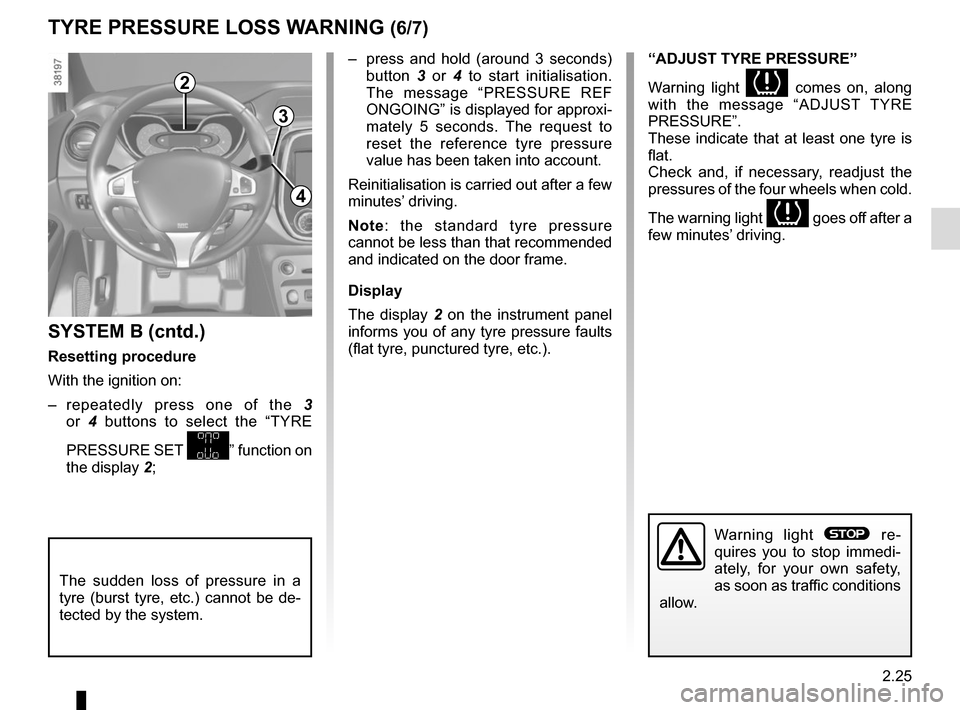
Display
The display 2 on the instrument panel
informs you of any tyre pressure faults
(flat tyre, punctured tyre, etc.).
SYSTEM B (cntd.)
Resetting procedure
With the ignition on:
– repeatedly press one of the 3
or 4 buttons to select the “TYRE
PRESSURE SET
” function on
the display 2;
“ADJUST TYRE PRESSURE”
Warning light
comes on, along
with the message “ADJUST TYRE
PRESSURE”.
These indicate that at least one tyre is
flat.
Check and, if necessary, readjust the
pressures of the four wheels when cold.
The warning light
goes off after a
few minutes’ driving.
The sudden loss of pressure in a
tyre (burst tyre, etc.) cannot be de-
tected by the system.
Warning light ® re-
quires you to stop immedi-
ately, for your own safety,
as soon as traffic conditions
allow.
Page 112 of 248
2.30
Grip control
If fitted on the vehicle, grip control
makes it easier to control the vehicle on
low grip surfaces (soft ground, etc.).
Tyres
When they need to be re-
placed, only tyres of the
same make, size, type and
profile should be used.
Tyres fitted to the vehicle should
either be identical to those fitted
originally or conform to those
recommended by your approved
dealer.
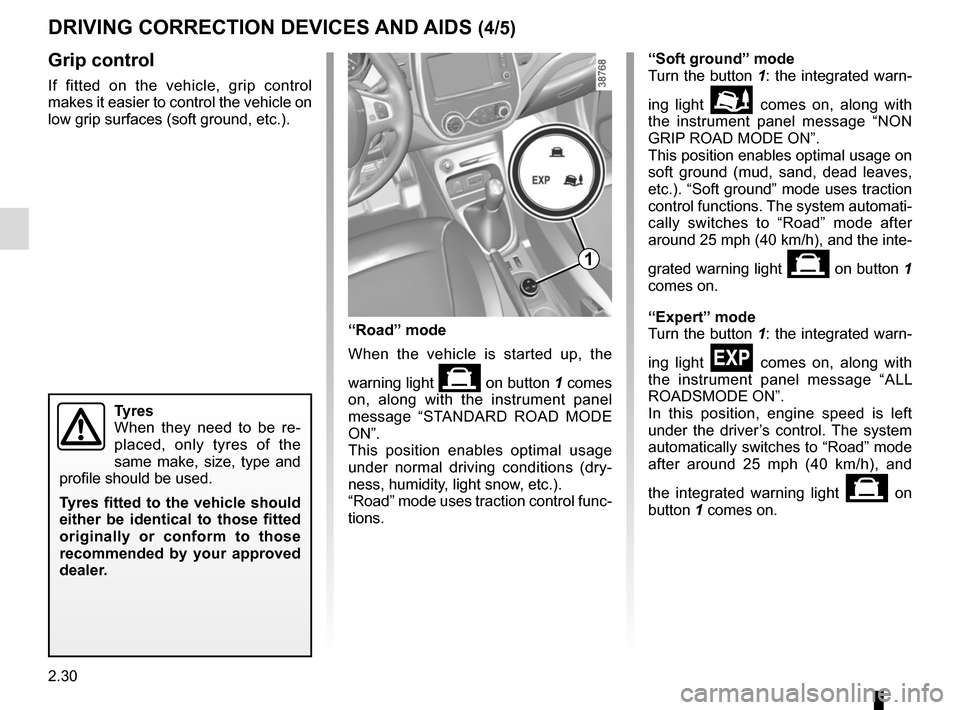
“Soft ground” mode
Turn the button 1: the integrated warn-
ing light
\b comes on, along with
the instrument panel message “NON
GRIP ROAD MODE ON”.
This position enables optimal usage on
soft ground (mud, sand, dead leaves,
etc.). “Soft ground” mode uses traction
control functions. The system automati-
cally switches to “Road” mode after
around 25 mph (40 km/h), and the inte-
grated warning light
on button 1
comes on.
“Expert” mode
Turn the button 1: the integrated warn-
ing light
comes on, along with
the instrument panel message “ALL
ROADSMODE ON”.
In this position, engine speed is left
under the driver’s control. The system
automatically switches to “Road” mode
after around 25 mph (40 km/h), and
the integrated warning light
on
button 1 comes on.
“Road” mode
When the vehicle is started up, the
warning light
on button 1 comes
on, along with the instrument panel
message “STANDARD ROAD MODE
ON”.
This position enables optimal usage
under normal driving conditions (dry-
ness, humidity, light snow, etc.).
“Road” mode uses traction control func-
tions.
1
DRIVING CORRECTION DEVICES AND AIDS (4/5)
Page 125 of 248
2.43
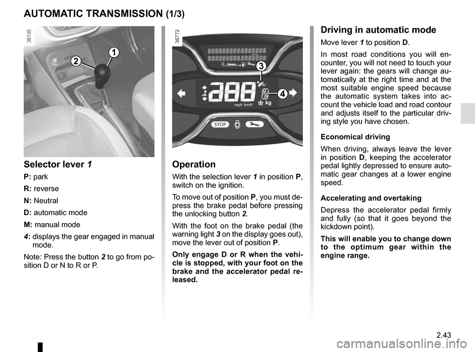
AUTOMATIC TRANSMISSION (1/3)
Operation
With the selection lever 1 in position P,
switch on the ignition.
To move out of position P, you must de-
press the brake pedal before pressing
the unlocking button 2.
With the foot on the brake pedal (the
warning light 3 on the display goes out),
move the lever out of position P.
Only engage D or R when the vehi-
cle is stopped, with your foot on the
brake and the accelerator pedal re-
leased.
Selector lever 1
P: park
R: reverse
N: Neutral
D: automatic mode
M: manual mode
4: displays the gear engaged in manual
mode.
Note: Press the button 2 to go from po-
sition D or N to R or P.
1
4
32
Driving in automatic mode
Move lever 1 to position D.
In most road conditions you will en-
counter, you will not need to touch your
lever again: the gears will change au-
tomatically at the right time and at the
most suitable engine speed because
the automatic system takes into ac-
count the vehicle load and road contour
and adjusts itself to the particular driv-
ing style you have chosen.
Economical driving
When driving, always leave the lever
in position D, keeping the accelerator
pedal lightly depressed to ensure auto-
matic gear changes at a lower engine
speed.
Accelerating and overtaking
Depress the accelerator pedal firmly
and fully (so that it goes beyond the
kickdown point).
This will enable you to change down
to the optimum gear within the
engine range.
Page 132 of 248
3.4
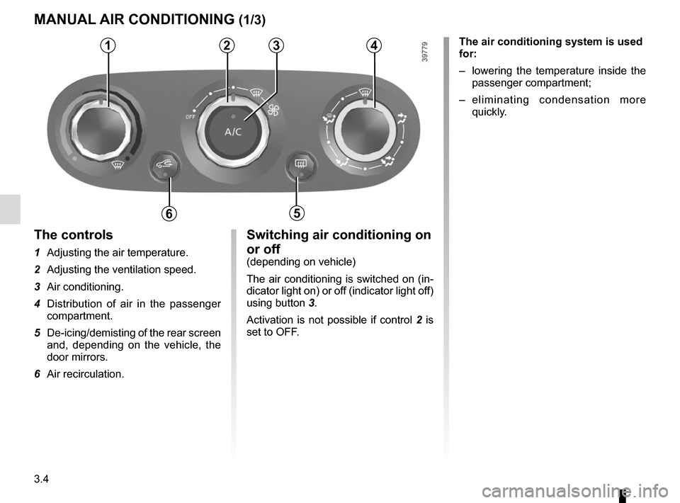
Switching air conditioning on
or off
(depending on vehicle)
The air conditioning is switched on (in-
dicator light on) or off (indicator light off)
using button 3.
Activation is not possible if control 2 is
set to OFF.
The controls
1 Adjusting the air temperature.
2 Adjusting the ventilation speed.
3 Air conditioning.
4 Distribution of air in the passenger compartment.
5 De-icing/demisting of the rear screen and, depending on the vehicle, the
door mirrors.
6 Air recirculation.
MANUAL AIR CONDITIONING (1/3)
1234
65
The air conditioning system is used
for:
– lowering the temperature inside the
passenger compartment;
– eliminating condensation more quickly.
Page 133 of 248
3.5
Air recirculation is for:
– isolating the vehicle from the exter-nal atmosphere (driving in polluted
areas, etc.);
– lowering the passenger compart- ment temperature as quickly as pos-
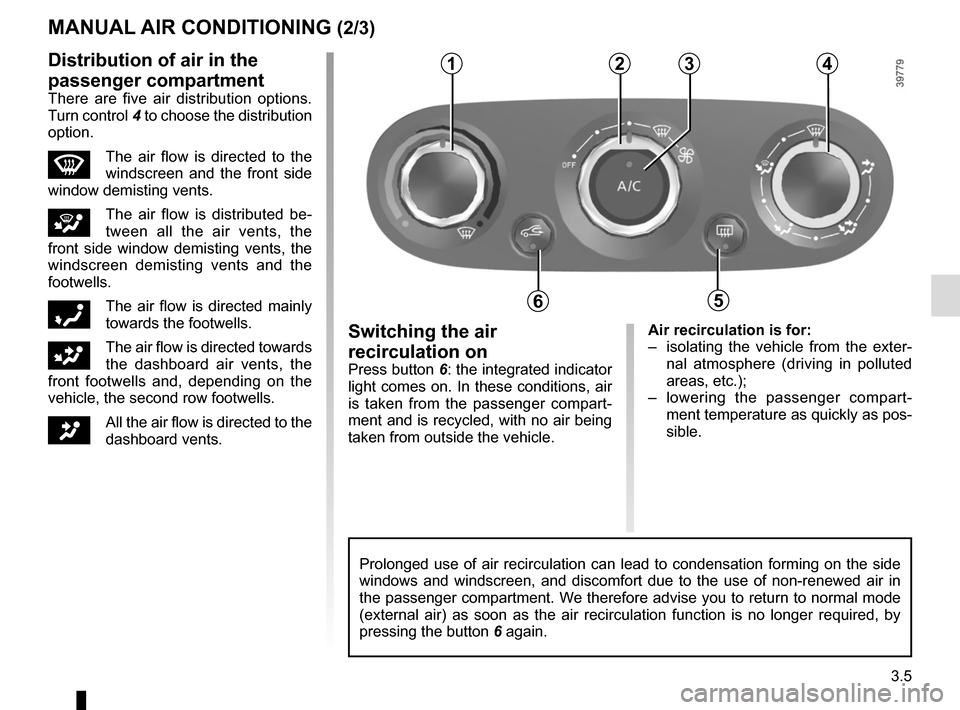
sible.Switching the air
recirculation on
Press button 6: the integrated indicator
light comes on. In these conditions, air
is taken from the passenger compart-
ment and is recycled, with no air being
taken from outside the vehicle.
MANUAL AIR CONDITIONING (2/3)
Prolonged use of air recirculation can lead to condensation forming on t\
he side
windows and windscreen, and discomfort due to the use of non-renewed air\
in
the passenger compartment. We therefore advise you to return to normal mode
(external air) as soon as the air recirculation function is no longer \
required, by
pressing the button 6 again.
1234
65
Distribution of air in the
passenger compartment
There are five air distribution options.
Turn control 4 to choose the distribution
option.
WThe air flow is directed to the
windscreen and the front side
window demisting vents.
iThe air flow is distributed be-
tween all the air vents, the
front side window demisting vents, the
windscreen demisting vents and the
footwells.
óThe air flow is directed mainly
towards the footwells.
GThe air flow is directed towards
the dashboard air vents, the
front footwells and, depending on the
vehicle, the second row footwells.
JAll the air flow is directed to the
dashboard vents.
Page 134 of 248
3.6
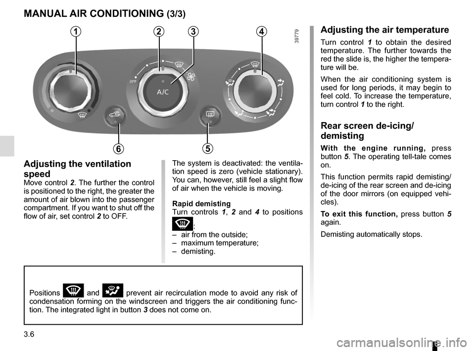
Adjusting the ventilation
speed
Move control 2. The further the control is positioned to the right, the greater the
amount of air blown into the passenger
compartment. If you want to shut off the
flow of air, set control 2 to OFF.
4
5
MANUAL AIR CONDITIONING (3/3)
The system is deactivated: the ventila-
tion speed is zero (vehicle stationary).
You can, however, still feel a slight flow
of air when the vehicle is moving.
Rapid demisting
Turn controls 1, 2 and 4 to positions
W:
– air from the outside;
– maximum temperature;
– demisting.
1234
65
Positions W and i prevent air recirculation mode to avoid any risk of
condensation forming on the windscreen and triggers the air conditioning\
func-
tion. The integrated light in button 3 does not come on.
Adjusting the air temperature
Turn control 1 to obtain the desired
temperature. The further towards the
red the slide is, the higher the tempera-
ture will be.
When the air conditioning system is
used for long periods, it may begin to
feel cold. To increase the temperature,
turn control 1 to the right.
Rear screen de-icing/
demisting
With the engine running, press
button 5. The operating tell-tale comes
on.
This function permits rapid demisting/
de-icing of the rear screen and de-icing
of the door mirrors (on equipped vehi-
cles).
To exit this function, press button 5
again.
Demisting automatically stops.
Page 135 of 248
3.7
Varying the ventilation speed
In automatic mode, the system uses
the most suitable amount of air to reach
and maintain the desired comfort level.
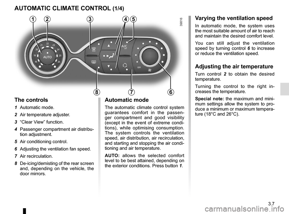
You can still adjust the ventilation
speed by turning control 6 to increase
or reduce the ventilation speed.
Adjusting the air temperature
Turn control 2 to obtain the desired
temperature.
Turning the control to the right in-
creases the temperature.
Special note: the maximum and mini-
mum settings allow the system to pro-
duce a minimum or maximum tempera-
ture (18°C and 26°C).
The controls
1 Automatic mode.
2 Air temperature adjuster.
3 “Clear View” function.
4 Passenger compartment air distribu-
tion adjustment.
5 Air conditioning control.
6 Adjusting the ventilation fan speed.
7 Air recirculation.
8 De-icing/demisting of the rear screen
and, depending on the vehicle, the
door mirrors.
AUTOMATIC CLIMATE CONTROL (1/4)
235
786
Automatic mode
The automatic climate control system
guarantees comfort in the passen-
ger compartment and good visibility
(except in the event of extreme condi-
tions), while optimising consumption.
The system controls the ventilation
speed, air distribution, air recirculation,
and starting and stopping the air condi-
tioning and air temperature.
AUTO: allows the selected comfort
level to be best attained, depending on
the exterior conditions. Press button 1.
14
Page 136 of 248
3.8
Clear View function
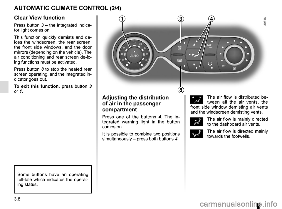
Press button 3 – the integrated indica-
tor light comes on.
This function quickly demists and de-
ices the windscreen, the rear screen,
the front side windows, and the door
mirrors (depending on the vehicle). The
air conditioning and rear screen de-ic-
ing functions must be activated.
Press button 8 to stop the heated rear
screen operating, and the integrated in-
dicator goes out.
To exit this function, press button 3
or 1.
AUTOMATIC CLIMATE CONTROL (2/4)
ØThe air flow is distributed be-
tween all the air vents, the
front side window demisting air vents
and the windscreen demisting vents.
½The air flow is mainly directed
to the dashboard air vents.
¿The air flow is directed mainly
towards the footwells.
Adjusting the distribution
of air in the passenger
compartment
Press one of the buttons 4 . The in-
tegrated warning light in the button
comes on.
It is possible to combine two positions
simultaneously – press both buttons 4.
8
3
Some buttons have an operating
tell-tale which indicates the operat-
ing status.
14