engine RENAULT KANGOO 1998 KC / 1.G Heating And Ventilation User Guide
[x] Cancel search | Manufacturer: RENAULT, Model Year: 1998, Model line: KANGOO, Model: RENAULT KANGOO 1998 KC / 1.GPages: 73
Page 48 of 73
c11010.0
AIR CONDITIONING
Fault finding charts
62
KANGOO
ALL TYPES
AFTER
REPAIR
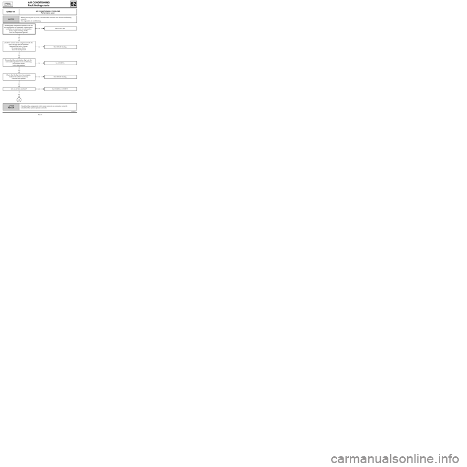
CHART 14AIR CONDITIONING PROBLEMS
Performance poor
NOTES
noSee CHART 14A.
noEnd of fault finding.
noSee CHART 11.
noEnd of fault finding.
Is it an air flow problem?yesSee CHART 2 or CHART 9.
no
A
yes
yes
yes
Before carrying out any work, check that the customer uses the air conditioning
correctly.
Non regulated air conditioning.
Check that the compressor operates, with the
air conditioning on, passenger compartment
ventilation on maximum in recirculation
mode, engine running at idle.
Does the compressor operate?
Check the tension of the compressor belt, the
clutch air gap and its condition.
Retension the belt or change
the compressor clutch.
Does the fault persist?
yes
Ensure that the recirculation flap is in the
recirculation position in air conditioning
recirculation mode.
Is it in this position?
Check that the flap travel is complete,
readjust the cable if necessary.
Does the fault persist?
Check that the components which were removed are connected correctly.
Check that the system operates correctly.
62-37
Page 49 of 73
yes
c11010.0
CONDITIONING
Fault finding charts
62
KANGOO
ALL TYPES
AFTER
REPAIR
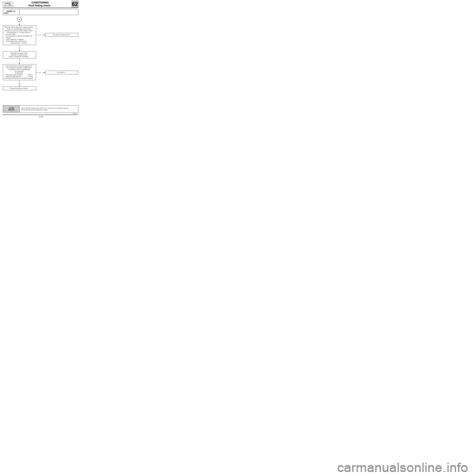
CHART 14
CONT
noTop up the coolant circuit.
yes
noSee CHART 15.
Change the pressure sensor.
Check the cleanness of the
condenser wiring harness.
Clean or change the condenser.
If the fault persists, check the operation of
the cooling fan assembly at high speed
(ventilation and air conditioning
on maximum).
It should be:
- operating if high pressure≥ 20 bars
- stopped if high pressure≤ 15 bars
Is the operation of the fan assembly normal?
Check that the components which were removed are connected correctly.
Check that the system operates correctly.
A
With the vehicle stationary, engine running
at idle, air conditioning on maximum,
measure the pressure of the coolant circuit.
If the pressure is > 28 bars, there is :
- too much fluid,
- or the operation of the fan assembly is ab-
normal,
- or the condenser is clogged,
- or the engine heats up too much.
Is the pressure < 28 bars ?
62-38
Page 50 of 73
yes
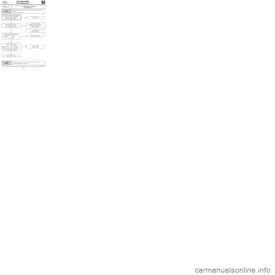
Check the electrical wiring:
air 9 1 pressure
conditioning 10 4 sensor
computer 11 3 connector
and between the connector and the sensor.
Is the wiring in good condition?
c11010.0
AIR CONDITIONING
Fault finding charts
62
KANGOO
ALL TYPES
AFTER
REPAIR
CHART 14AAIR CONDITIONING PROBLEMS
Performance poor
NOTES
yesSee CHART 14.
no
no
If the fault persists,
change the compressor.
yes
noRepair the faulty
electrical wiring.
yes
noTop up the coolant circuit.
Change the pressure sensor.
Before carrying out any work, check that the customer uses the air conditioning
correctly.
Non regulated air conditioning.
With the air conditioning and ventilation on
maximum and the engine running at idle,
check that the compressor operates.
Does the compressor operate?
Connect the XR25 and enter G21*
(direct compressor control).
Does the compressor operate?
Check the pressure of the coolant circuit.
The compressor should cut in for:
- low pressure≥ 2 bars,
- high pressure≤ 28 bars.
Is this correct?
Check the wiring between
the heating and ventilation computer
and the compressor clutch.
Repair if necessary.
Check that the components which were removed are connected correctly.
Check that the system operates correctly.
62-39
Page 54 of 73
c11010.0
AIR CONDITIONING
Fault finding - Associated checks
62
KANGOO
ALL TYPES
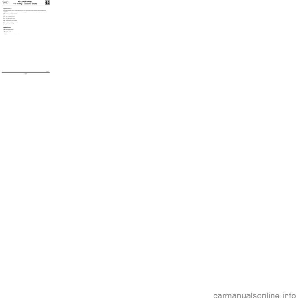
COMMAND MODE G--*
To use this function, enter G on the XR25 keypad, then the number of the command selected followed by
an asterisk.
G21* : compressor clutch control
G22* : fan low speed control
G23* : fan high speed control
G24* : recirculation motor control
G13* : end of fault finding
COMMAND MODE #
# 08 : fan assembly speed
# 15 : engine speed
# 16 : pressure of coolant in the circuit
62-43
Page 55 of 73
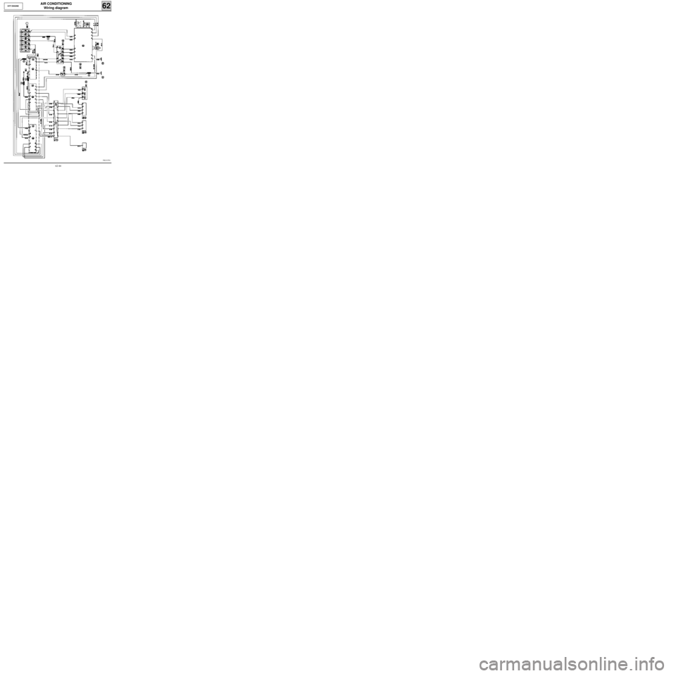
AIR CONDITIONING
Wiring diagram
62D7F ENGINE
PRO13781
62-44
Page 56 of 73
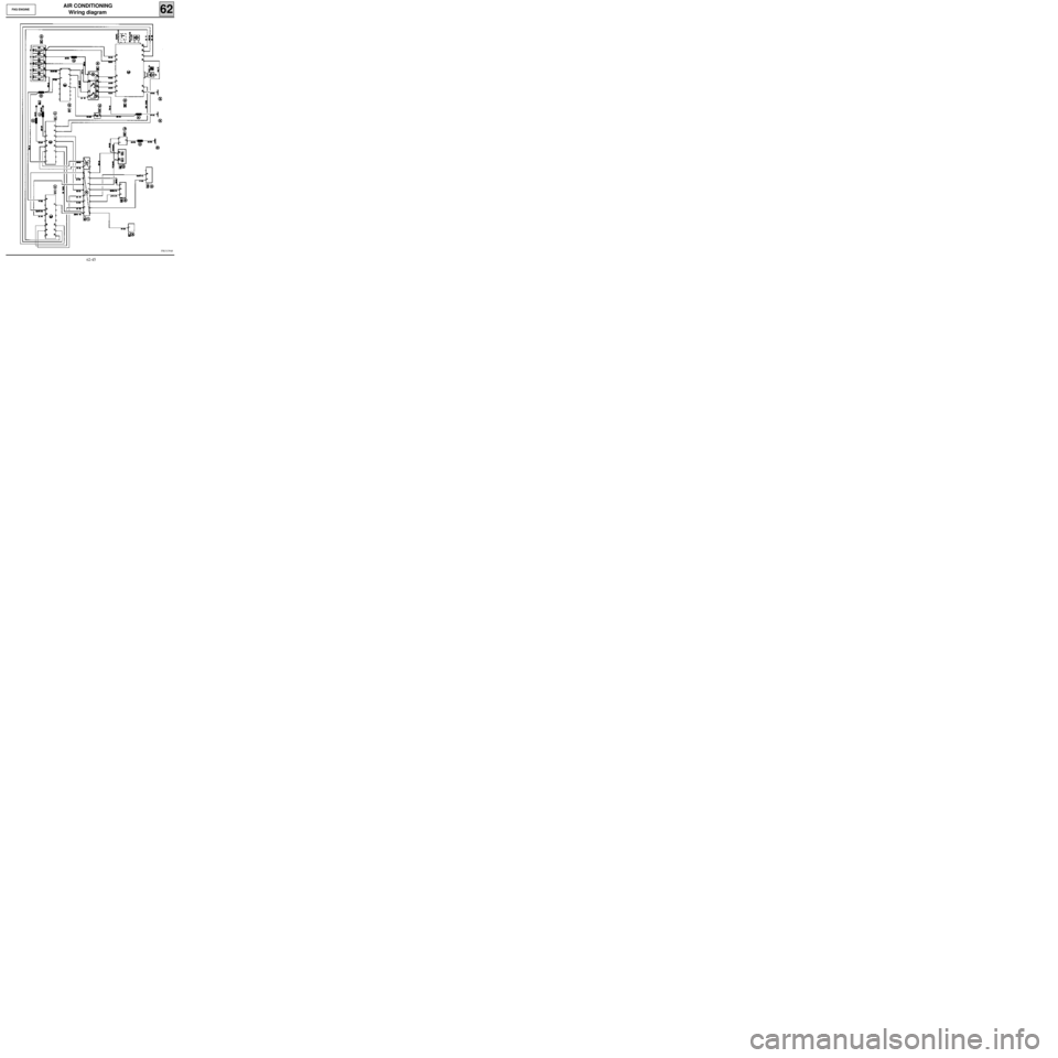
AIR CONDITIONING
Wiring diagram
62F8Q ENGINE
PRO13948
62-45
Page 57 of 73
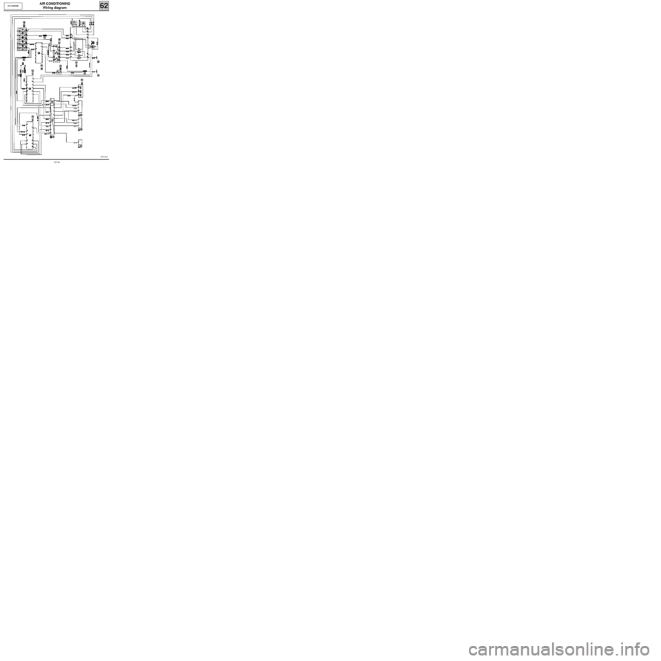
AIR CONDITIONING
Wiring diagram
62E7J ENGINE
PRO14441
62-46
Page 58 of 73
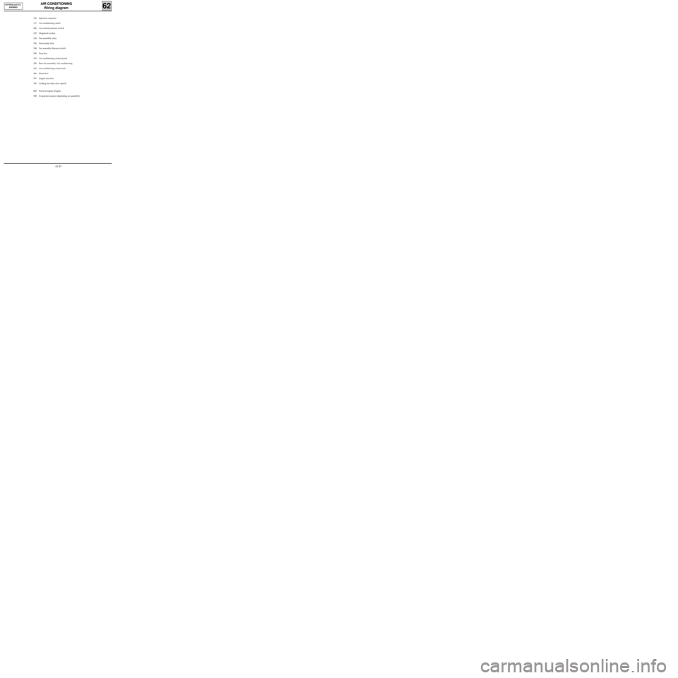
AIR CONDITIONING
Wiring diagram
62
D7F/F8Q and E7J
ENGINES
120 Injection computer
171 Air conditioning clutch
206 Air control pressure switch
225 Diagnostic socket
234 Fan assembly relay
236 Fuel pump relay
248 Fan assembly thermal switch
260 Fuse box
319 Air conditioning control panel
320 Base fan assembly/Air conditioning
419 Air conditioning control unit
466 Shunt box
597 Engine fuse box
700 Cooling fan relay (low speed)
R67 Front of engine/Engine
NB : Evaporator sensor (depending on assembly)
62-47
Page 62 of 73
AIR CONDITIONING
Compressor
62D7F ENGINE
13829R1
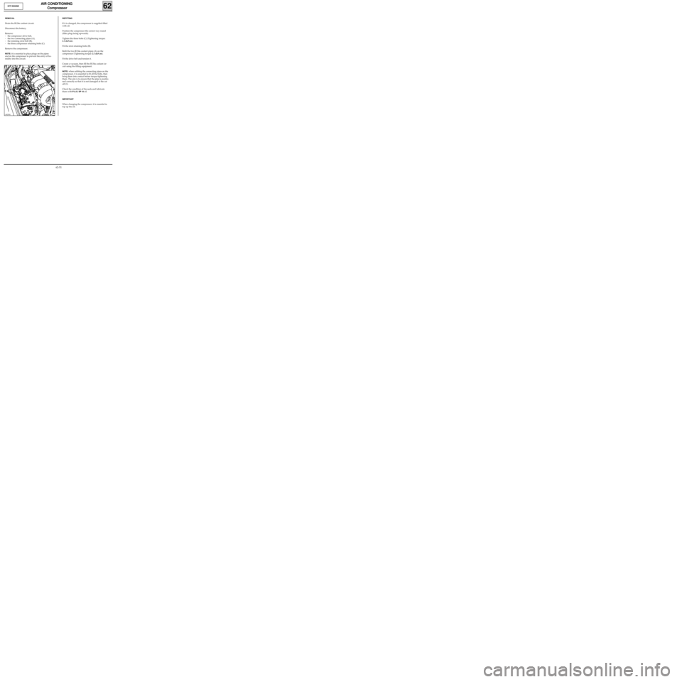
REMOVAL
Drain the R134a coolant circuit.
Disconnect the battery.
Remove:
- the compressor drive belt,
- the two connecting pipes (A),
- the retaining strut bolt (B),
- the three compressor retaining bolts (C).
Remove the compressor.
NOTE: it is essential to place plugs on the pipes
and on the compressor to prevent the entry of hu-
midity into the circuit.
REFITTING
If it is changed, the compressor is supplied filled
with oil.
Position the compressor the correct way round
(filler plug facing upwards).
Tighten the three bolts (C) (Tightening torque:
2.1 daN.m).
Fit the strut retaining bolts (B).
Refit the two R134a coolant pipes (A) on the
compressor (Tightening torque:
2.1 daN.m).
Fit the drive belt and tension it.
Create a vacuum, then fill the R134a coolant cir-
cuit using the filling equipment.
NOTE: when refitting the connecting pipes on the
compressor, it is essential to fit all the bolts, then
bring them into contact before torque tightening
them. The aim is to ensure that the pipe is positio-
ned correctly so that it is not damaged at the cut
off (1).
Check the condition of the seals and lubricate
them with
P.A.G. SP 10 oil.
IMPORTANT
When changing the compressor, it is essential to
top up the oil.
62-51
Page 63 of 73
AIR CONDITIONING
Compressor
62F8Q ENGINE
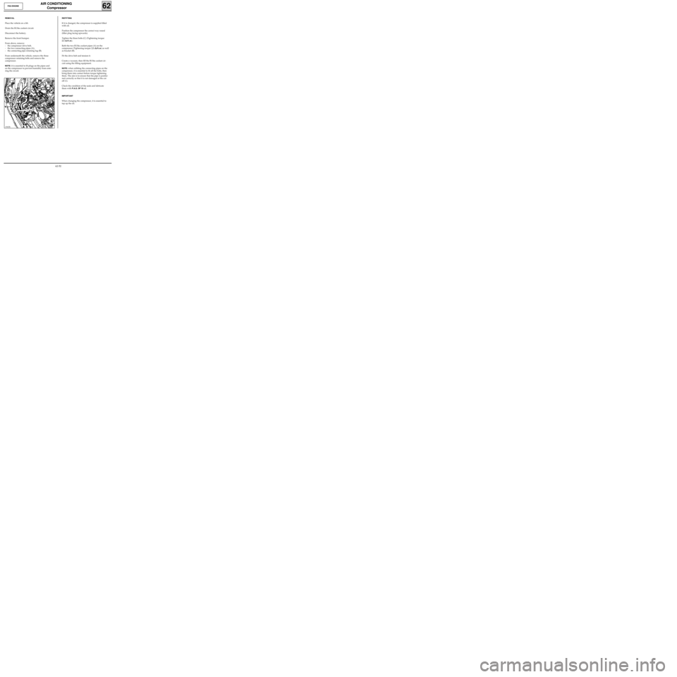
REMOVAL
Place the vehicle on a lift.
Drain the R134a coolant circuit.
Disconnect the battery.
Remove the front bumper.
From above, remove:
- the compressor drive belt,
- the two connecting pipes (A),
- the connecting pipe retaining lug (B).
From underneath the vehicle, remove the three
compressor retaining bolts and remove the
compressor.
NOTE: it is essential to fit plugs on the pipes and
on the compressor to prevent humidity from ente-
ring the circuit.
13947R
REFITTING
If it is changed, the compressor is supplied filled
with oil.
Position the compressor the correct way round
(filler plug facing upwards).
Tighten the three bolts (C) (Tightening torque:
2.1 daN.m).
Refit the two R134a coolant pipes (A) on the
compressor (Tightening torque:
2.1 daN.m) as well
as bracket (B).
Fit the drive belt and tension it.
Create a vacuum, then fill the R134a coolant cir-
cuit using the filling equipment.
NOTE: when refitting the connecting pipes on the
compressor, it is essential to fit all the bolts, then
bring them into contact before torque tightening
them. The aim is to ensure that the pipe is positio-
ned correctly so that it is not damaged at the cut
off (1).
Check the condition of the seals and lubricate
them with
P.A.G. SP 10 oil.
IMPORTANT
When changing the compressor, it is essential to
top up the oil.
62-52