engine RENAULT KANGOO 2013 X61 / 2.G Diesel DCM 1.2 Injection Owners Manual
[x] Cancel search | Manufacturer: RENAULT, Model Year: 2013, Model line: KANGOO, Model: RENAULT KANGOO 2013 X61 / 2.GPages: 204, PDF Size: 0.99 MB
Page 131 of 204
13B-131V1 MR-376-X76-13B000$080.mif
DIESEL INJECTION
Fault finding – Conformity check13B
DCM 1.2 Injection
Program no.: 4C
Vdiag No.: 08
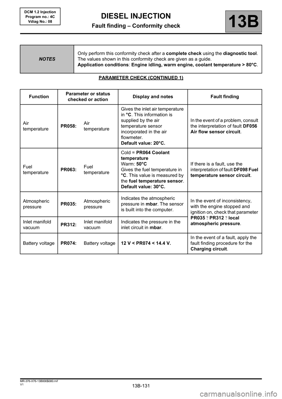
PARAMETER CHECK (CONTINUED 1)
NOTESOnly perform this conformity check after a complete check using the diagnostic tool.
The values shown in this conformity check are given as a guide.
Application conditions: Engine idling, warm engine, coolant temperature > 80°C.
FunctionParameter or status
checked or actionDisplay and notes Fault finding
Air
temperaturePR058:Air
temperatureGives the inlet air temperature
in °C. This information is
supplied by the air
temperature sensor
incorporated in the air
flowmeter.
Default value: 20°C.In the event of a problem, consult
the interpretation of fault DF056
Air flow sensor circuit.
Fuel
temperaturePR063:Fuel
temperatureCold = PR064 Coolant
temperature
Warm: 50°C
Gives the fuel temperature in
°C. This value is measured by
the fuel temperature sensor.
Default value: 30°C.If there is a fault, use the
interpretation of fault DF098 Fuel
temperature sensor circuit.
Atmospheric
pressurePR035:Atmospheric
pressureIndicates the atmospheric
pressure in mbar. The sensor
is built into the computer. In the event of inconsistency,
with the engine stopped and
ignition on, check that parameter
PR035PR312local
atmospheric pressure. Inlet manifold
vacuumPR312:Inlet manifold
vacuumIndicates the pressure in the
inlet circuit in mbar.
Battery voltagePR074:Battery voltage12 V < PR074 < 14.4 V.In the event of a fault, apply the
fault finding procedure for the
Charging circuit.
Page 132 of 204
13B-132V1 MR-376-X76-13B000$080.mif
DIESEL INJECTION
Fault finding – Conformity check13B
DCM 1.2 Injection
Program no.: 4C
Vdiag No.: 08
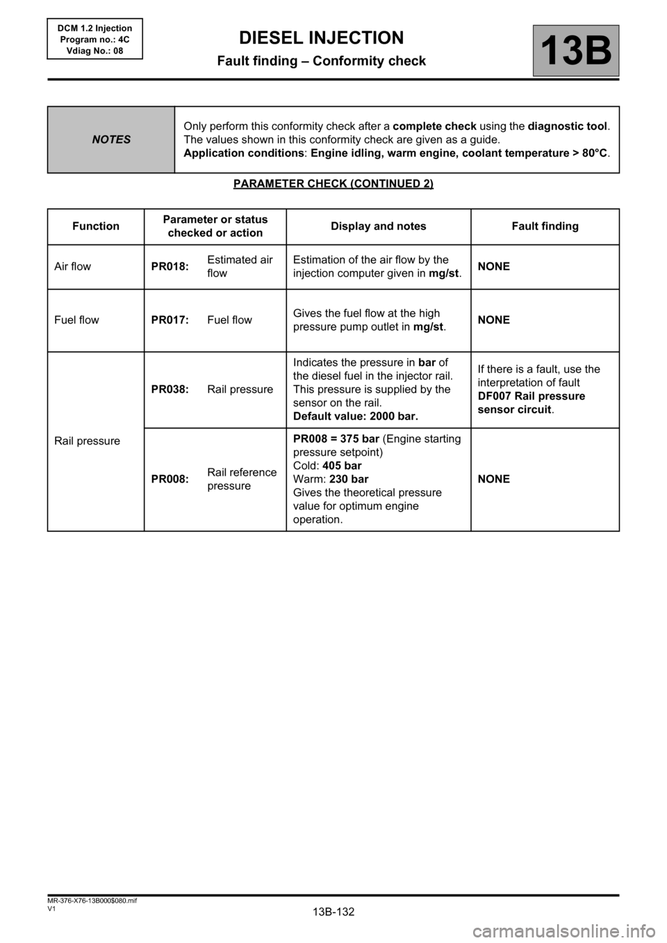
PARAMETER CHECK (CONTINUED 2)
NOTESOnly perform this conformity check after a complete check using the diagnostic tool.
The values shown in this conformity check are given as a guide.
Application conditions: Engine idling, warm engine, coolant temperature > 80°C.
FunctionParameter or status
checked or actionDisplay and notes Fault finding
Air flowPR018:Estimated air
flowEstimation of the air flow by the
injection computer given in mg/st.NONE
Fuel flowPR017:Fuel flowGives the fuel flow at the high
pressure pump outlet in mg/st.NONE
Rail pressurePR038:Rail pressureIndicates the pressure in bar of
the diesel fuel in the injector rail.
This pressure is supplied by the
sensor on the rail.
Default value: 2000 bar.If there is a fault, use the
interpretation of fault
DF007 Rail pressure
sensor circuit.
PR008:Rail reference
pressurePR008 = 375 bar (Engine starting
pressure setpoint)
Cold: 405 bar
Warm: 230 bar
Gives the theoretical pressure
value for optimum engine
operation.NONE
Page 133 of 204
13B-133V1 MR-376-X76-13B000$080.mif
DIESEL INJECTION
Fault finding – Conformity check13B
DCM 1.2 Injection
Program no.: 4C
Vdiag No.: 08
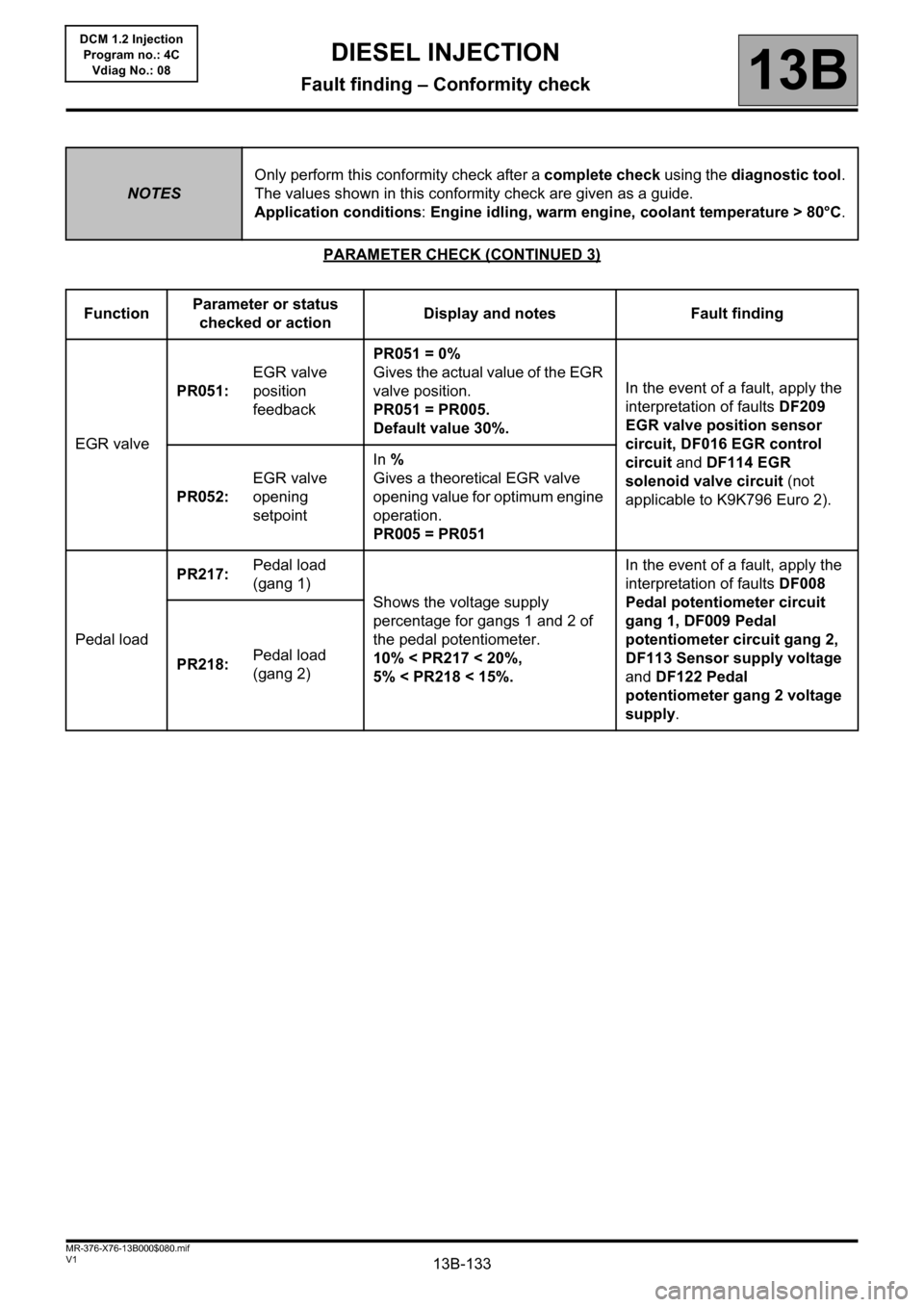
PARAMETER CHECK (CONTINUED 3)
NOTESOnly perform this conformity check after a complete check using the diagnostic tool.
The values shown in this conformity check are given as a guide.
Application conditions: Engine idling, warm engine, coolant temperature > 80°C.
FunctionParameter or status
checked or actionDisplay and notes Fault finding
EGR valvePR051:EGR valve
position
feedbackPR051 = 0%
Gives the actual value of the EGR
valve position.
PR051 = PR005.
Default value 30%.In the event of a fault, apply the
interpretation of faults DF209
EGR valve position sensor
circuit, DF016 EGR control
circuit and DF114 EGR
solenoid valve circuit (not
applicable to K9K796 Euro 2). PR052:EGR valve
opening
setpointIn %
Gives a theoretical EGR valve
opening value for optimum engine
operation.
PR005 = PR051
Pedal loadPR217:Pedal load
(gang 1)
Shows the voltage supply
percentage for gangs 1 and 2 of
the pedal potentiometer.
10% < PR217 < 20%,
5% < PR218 < 15%.In the event of a fault, apply the
interpretation of faults DF008
Pedal potentiometer circuit
gang 1, DF009 Pedal
potentiometer circuit gang 2,
DF113 Sensor supply voltage
and DF122 Pedal
potentiometer gang 2 voltage
supply. PR218:Pedal load
(gang 2)
Page 134 of 204

13B-134V1 MR-376-X76-13B000$080.mif
DIESEL INJECTION
Fault finding – Conformity check13B
DCM 1.2 Injection
Program no.: 4C
Vdiag No.: 08
PARAMETER CHECK (CONTINUED 4)
NOTESOnly perform this conformity check after a complete check using the diagnostic tool.
The values shown in this conformity check are given as a guide.
Application conditions: Engine idling, warm engine, coolant temperature > 80°C.
FunctionParameter or status
checked or actionDisplay and notes Fault finding
Sensor
voltagePR077:EGR valve
position
sensor voltage0.5 V < PR077 < 4.8 VIn the event of a fault, apply the
interpretation of fault DF209
EGR valve position sensor
circuit (not applicable to
K9K796 Euro 2).
PR344:Manifold
pressure
sensor voltageShows the voltage supplied by the
computer to feed the inlet pressure
sensor in volts.In the event of a fault, apply the
interpretation of fault DF089
Inlet manifold pressure
sensor circuit.
PR080:Rail pressure
sensor voltage0.5 V < PR080 < 4.5 V
Shows the voltage supplied by the
computer on the rail pressure
sensor in volts.
Default value: 4.5 V.In the event of a problem, apply
the interpretation of DF007 Rail
pressure sensor circuit.
PressurePR037:Refrigerant
pressure2 bar < PR037 < 27 bar
Shows the value of the refrigerant
fluid pressure in the system in bar.
Default value: 0 bar.In the event of a fault, apply the
interpretation of fault DF049
Refrigerant sensor circuit.
Air flowPR019:Linearised air
flowShows the linearised air flow in g/s.In the event of a fault, apply the
interpretation of fault DF056 Air
flow sensor circuit.
Page 135 of 204
13B-135V1 MR-376-X76-13B000$090.mif
13B
DCM 1.2 Injection
Program no.: 4C
Vdiag No.: 08
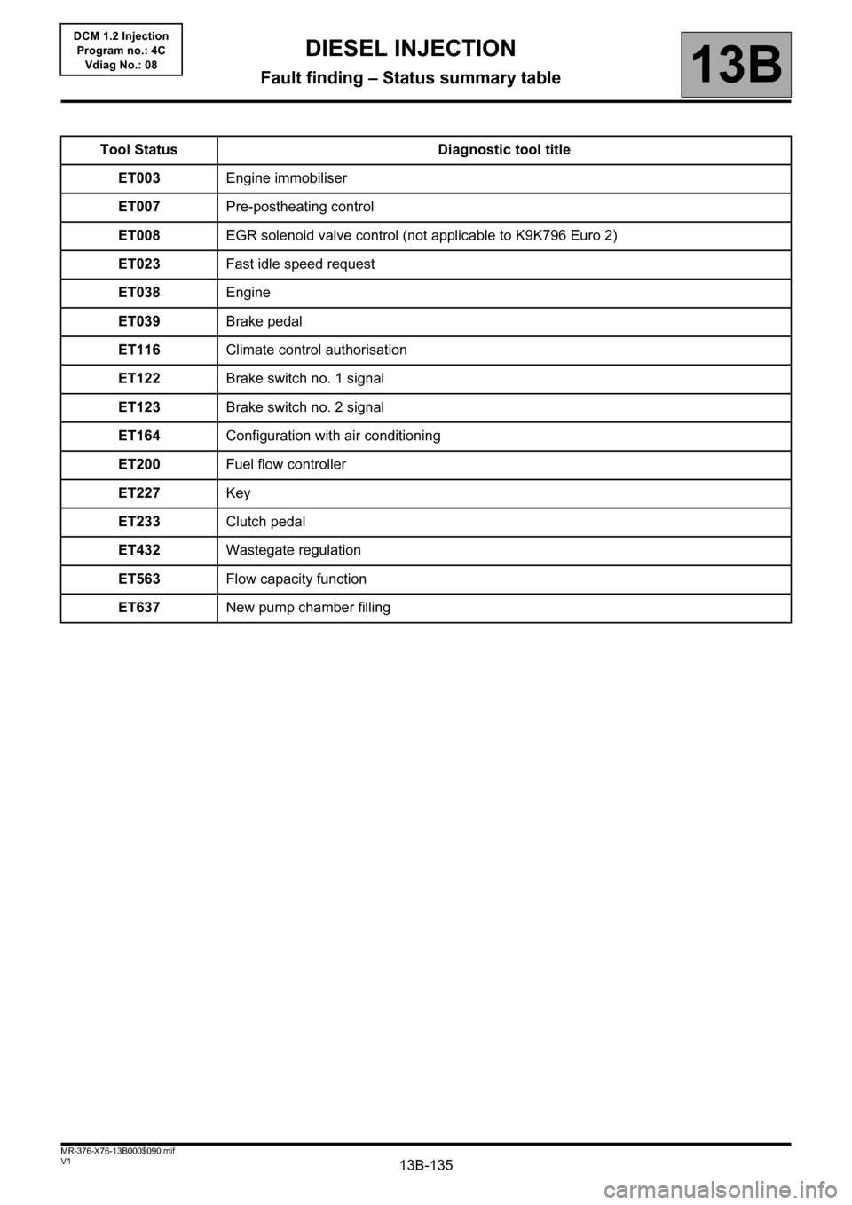
Tool Status Diagnostic tool title
ET003Engine immobiliser
ET007Pre-postheating control
ET008EGR solenoid valve control (not applicable to K9K796 Euro 2)
ET023Fast idle speed request
ET038Engine
ET039Brake pedal
ET116Climate control authorisation
ET122Brake switch no. 1 signal
ET123Brake switch no. 2 signal
ET164Configuration with air conditioning
ET200Fuel flow controller
ET227Key
ET233Clutch pedal
ET432Wastegate regulation
ET563Flow capacity function
ET637New pump chamber filling
DIESEL INJECTION
Fault finding – Status summary table
Page 136 of 204
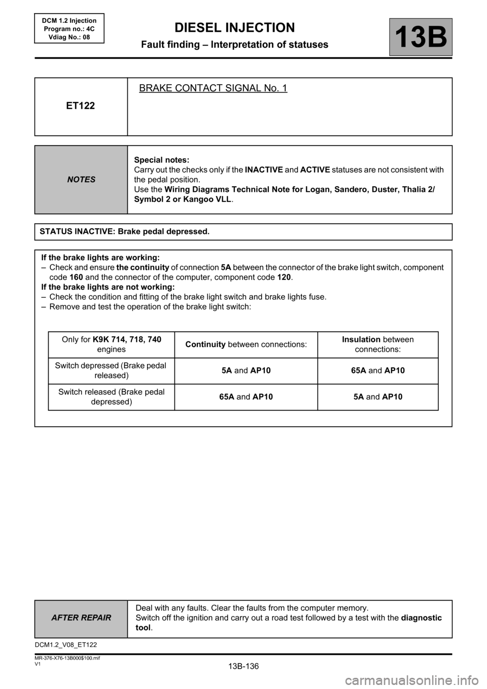
13B-136
AFTER REPAIRDeal with any faults. Clear the faults from the computer memory.
Switch off the ignition and carry out a road test followed by a test with the diagnostic
tool.
V1 MR-376-X76-13B000$100.mif
13B
DCM 1.2 Injection
Program no.: 4C
Vdiag No.: 08
ET122BRAKE CONTACT SIGNAL No. 1
NOTESSpecial notes:
Carry out the checks only if the INACTIVE and ACTIVE statuses are not consistent with
the pedal position.
Use the Wiring Diagrams Technical Note for Logan, Sandero, Duster, Thalia 2/
Symbol 2 or Kangoo VLL.
STATUS INACTIVE: Brake pedal depressed.
If the brake lights are working:
– Check and ensure the continuity of connection 5A between the connector of the brake light switch, component
code 160 and the connector of the computer, component code 120.
If the brake lights are not working:
– Check the condition and fitting of the brake light switch and brake lights fuse.
– Remove and test the operation of the brake light switch:
Only for K9K 714, 718, 740
enginesContinuity between connections:Insulation between
connections:
Switch depressed (Brake pedal
released)5A and AP10 65A and AP10
Switch released (Brake pedal
depressed)65A and AP10 5A and AP10
DCM1.2_V08_ET122
DIESEL INJECTION
Fault finding – Interpretation of statuses
Page 137 of 204
13B-137
AFTER REPAIRDeal with any faults. Clear the faults from the computer memory.
Switch off the ignition and carry out a road test followed by a test with the diagnostic
tool.
V1 MR-376-X76-13B000$100.mif
DIESEL INJECTION
Fault finding – Interpretation of statuses13B
DCM 1.2 Injection
Program no.: 4C
Vdiag No.: 08
ET122
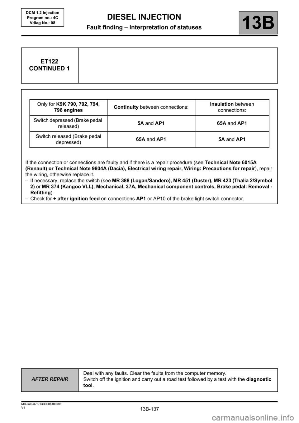
CONTINUED 1
Only for K9K 790, 792, 794,
796 enginesContinuity between connections:Insulation between
connections:
Switch depressed (Brake pedal
released)5A and AP1 65A and AP1
Switch released (Brake pedal
depressed)65A and AP1 5A and AP1
If the connection or connections are faulty and if there is a repair procedure (see Technical Note 6015A
(Renault) or Technical Note 9804A (Dacia), Electrical wiring repair, Wiring: Precautions for repair), repair
the wiring, otherwise replace it.
– If necessary, replace the switch (see MR 388 (Logan/Sandero), MR 451 (Duster), MR 423 (Thalia 2/Symbol
2) or MR 374 (Kangoo VLL), Mechanical, 37A, Mechanical component controls, Brake pedal: Removal -
Refitting).
– Check for + after ignition feed on connections AP1 or AP10 of the brake light switch connector.
Page 138 of 204
13B-138
AFTER REPAIRDeal with any faults. Clear the faults from the computer memory.
Switch off the ignition and carry out a road test followed by a test with the diagnostic
tool.
V1 MR-376-X76-13B000$100.mif
DIESEL INJECTION
Fault finding – Interpretation of statuses13B
DCM 1.2 Injection
Program no.: 4C
Vdiag No.: 08
ET122
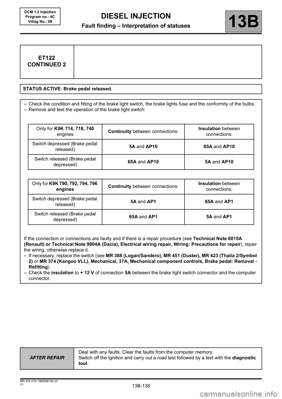
CONTINUED 2
STATUS ACTIVE: Brake pedal released.
– Check the condition and fitting of the brake light switch, the brake lights fuse and the conformity of the bulbs.
– Remove and test the operation of the brake light switch:
Only for K9K 714, 718, 740
enginesContinuity between connections:Insulation between
connections:
Switch depressed (Brake pedal
released)5A and AP10 65A and AP10
Switch released (Brake pedal
depressed)65A and AP10 5A and AP10
Only for K9K 790, 792, 794, 796
enginesContinuity between connections:Insulation between
connections:
Switch depressed (Brake pedal
released)5A and AP1 65A and AP1
Switch released (Brake pedal
depressed)65A and AP1 5A and AP1
If the connection or connections are faulty and if there is a repair procedure (see Technical Note 6015A
(Renault) or Technical Note 9804A (Dacia), Electrical wiring repair, Wiring: Precautions for repair), repair
the wiring, otherwise replace it.
– If necessary, replace the switch (see MR 388 (Logan/Sandero), MR 451 (Duster), MR 423 (Thalia 2/Symbol
2) or MR 374 (Kangoo VLL), Mechanical, 37A, Mechanical component controls, Brake pedal: Removal -
Refitting).
– Check the insulation to + 12 V of connection 5A between the brake light switch connector and the computer
connector.
Page 139 of 204
13B-139
AFTER REPAIRDeal with any faults. Clear the faults from the computer memory.
Switch off the ignition and carry out a road test followed by a test with the diagnostic
tool.
V1 MR-376-X76-13B000$100.mif
DIESEL INJECTION
Fault finding – Interpretation of statuses13B
DCM 1.2 Injection
Program no.: 4C
Vdiag No.: 08
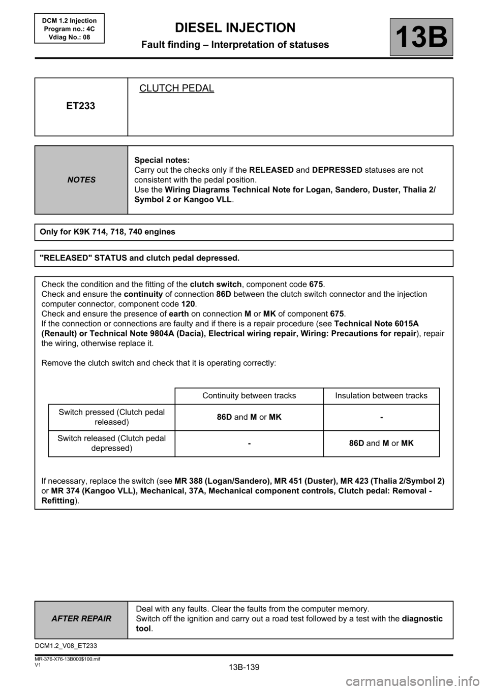
ET233CLUTCH PEDAL
NOTESSpecial notes:
Carry out the checks only if the RELEASED and DEPRESSED statuses are not
consistent with the pedal position.
Use the Wiring Diagrams Technical Note for Logan, Sandero, Duster, Thalia 2/
Symbol 2 or Kangoo VLL.
Only for K9K 714, 718, 740 engines
"RELEASED" STATUS and clutch pedal depressed.
Check the condition and the fitting of the clutch switch, component code 675.
Check and ensure the continuity of connection 86D between the clutch switch connector and the injection
computer connector, component code 120.
Check and ensure the presence of earth on connection M or MK of component 675.
If the connection or connections are faulty and if there is a repair procedure (see Technical Note 6015A
(Renault) or Technical Note 9804A (Dacia), Electrical wiring repair, Wiring: Precautions for repair), repair
the wiring, otherwise replace it.
Remove the clutch switch and check that it is operating correctly:
Continuity between tracks Insulation between tracks
Switch pressed (Clutch pedal
released)86D and M or MK -
Switch released (Clutch pedal
depressed)-86D and M or MK
If necessary, replace the switch (see MR 388 (Logan/Sandero), MR 451 (Duster), MR 423 (Thalia 2/Symbol 2)
or MR 374 (Kangoo VLL), Mechanical, 37A, Mechanical component controls, Clutch pedal: Removal -
Refitting).
DCM1.2_V08_ET233
Page 141 of 204
13B-141V1 MR-376-X76-13B000$110.mif
13B
DCM 1.2 Injection
Program no.: 4C
Vdiag No.: 08
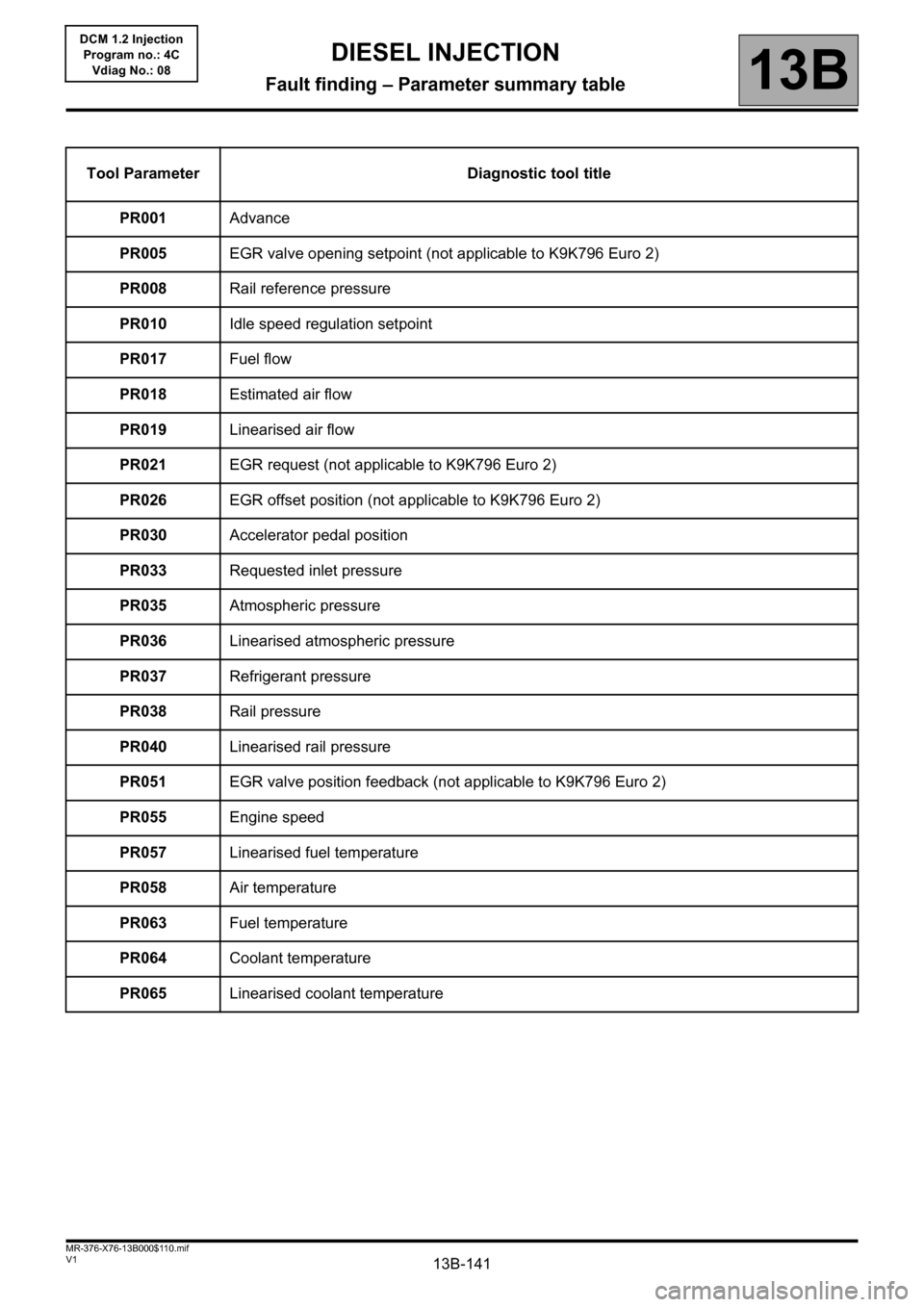
Tool Parameter Diagnostic tool title
PR001Advance
PR005EGR valve opening setpoint (not applicable to K9K796 Euro 2)
PR008Rail reference pressure
PR010Idle speed regulation setpoint
PR017Fuel flow
PR018Estimated air flow
PR019Linearised air flow
PR021EGR request (not applicable to K9K796 Euro 2)
PR026EGR offset position (not applicable to K9K796 Euro 2)
PR030Accelerator pedal position
PR033Requested inlet pressure
PR035Atmospheric pressure
PR036Linearised atmospheric pressure
PR037Refrigerant pressure
PR038Rail pressure
PR040Linearised rail pressure
PR051EGR valve position feedback (not applicable to K9K796 Euro 2)
PR055Engine speed
PR057Linearised fuel temperature
PR058Air temperature
PR063Fuel temperature
PR064Coolant temperature
PR065Linearised coolant temperature
DIESEL INJECTION
Fault finding – Parameter summary table