diagram RENAULT KANGOO 2013 X61 / 2.G Diesel DCM 1.2 Injection Repair Manual
[x] Cancel search | Manufacturer: RENAULT, Model Year: 2013, Model line: KANGOO, Model: RENAULT KANGOO 2013 X61 / 2.GPages: 204, PDF Size: 0.99 MB
Page 110 of 204
13B-110
AFTER
REPAIRDeal with any faults declared by the diagnostic tool.
Clear the computer memory.
Carry out a road test followed by another check with the diagnostic tool.
V1 MR-376-X76-13B000$072.mif
DIESEL INJECTION
Fault finding – Interpretation of faults13B
DCM 1.2 Injection
Program no.: 4C
Vdiag No.: 08
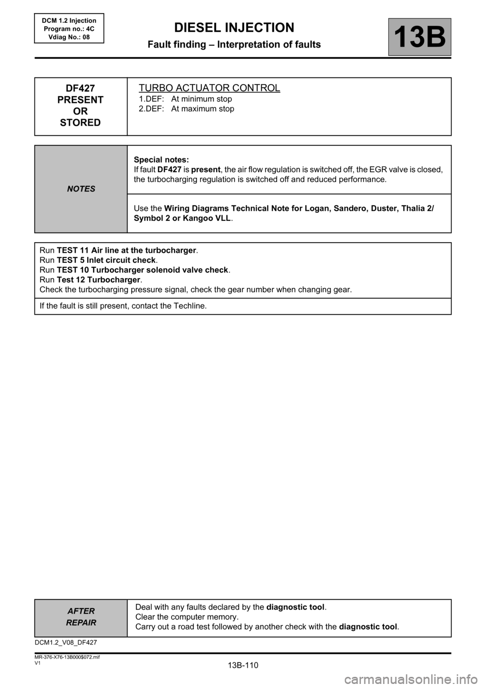
DF427
PRESENT
OR
STOREDTURBO ACTUATOR CONTROL
1.DEF: At minimum stop
2.DEF: At maximum stop
NOTESSpecial notes:
If fault DF427 is present, the air flow regulation is switched off, the EGR valve is closed,
the turbocharging regulation is switched off and reduced performance.
Use the Wiring Diagrams Technical Note for Logan, Sandero, Duster, Thalia 2/
Symbol 2 or Kangoo VLL.
Run TEST 11 Air line at the turbocharger.
Run TEST 5 Inlet circuit check.
Run TEST 10 Turbocharger solenoid valve check.
Run Test 12 Turbocharger.
Check the turbocharging pressure signal, check the gear number when changing gear.
If the fault is still present, contact the Techline.
DCM1.2_V08_DF427
Page 112 of 204
13B-112
AFTER
REPAIRDeal with any faults declared by the diagnostic tool.
Clear the computer memory.
Carry out a road test followed by another check with the diagnostic tool.
V1 MR-376-X76-13B000$072.mif
DIESEL INJECTION
Fault finding – Interpretation of faults13B
DCM 1.2 Injection
Program no.: 4C
Vdiag No.: 08
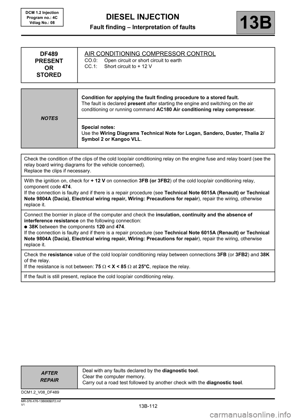
DF489
PRESENT
OR
STOREDAIR CONDITIONING COMPRESSOR CONTROL
CO.0: Open circuit or short circuit to earth
CC.1: Short circuit to + 12 V
NOTESCondition for applying the fault finding procedure to a stored fault.
The fault is declared present after starting the engine and switching on the air
conditioning or running command AC180 Air conditioning relay compressor.
Special notes:
Use the Wiring Diagrams Technical Note for Logan, Sandero, Duster, Thalia 2/
Symbol 2 or Kangoo VLL.
Check the condition of the clips of the cold loop/air conditioning relay on the engine fuse and relay board (see the
relay board wiring diagrams for the vehicle concerned).
Replace the clips if necessary.
With the ignition on, check for + 12 V on connection 3FB (or 3FB2) of the cold loop/air conditioning relay,
component code 474.
If the connection is faulty and if there is a repair procedure (see Technical Note 6015A (Renault) or Technical
Note 9804A (Dacia), Electrical wiring repair, Wiring: Precautions for repair), repair the wiring, otherwise
replace it.
Connect the bornier in place of the computer and check the insulation, continuity and the absence of
interference resistance on the following connection:
●38K between the components 120 and 474.
If the connection is faulty and if there is a repair procedure (see Technical Note 6015A (Renault) or Technical
Note 9804A (Dacia), Electrical wiring repair, Wiring: Precautions for repair), repair the wiring, otherwise
replace it.
Check the resistance value of the cold loop/air conditioning relay between connections 3FB (or 3FB2) and 38K
of the relay.
If the resistance is not between: 75 < X < 85 at 25°C, replace the relay.
If the fault is still present, replace the cold loop/air conditioning relay.
DCM1.2_V08_DF489
Page 113 of 204
13B-113
AFTER
REPAIRDeal with any faults declared by the diagnostic tool.
Clear the computer memory.
Carry out a road test followed by another check with the diagnostic tool.
V1 MR-376-X76-13B000$072.mif
DIESEL INJECTION
Fault finding – Interpretation of faults13B
DCM 1.2 Injection
Program no.: 4C
Vdiag No.: 08
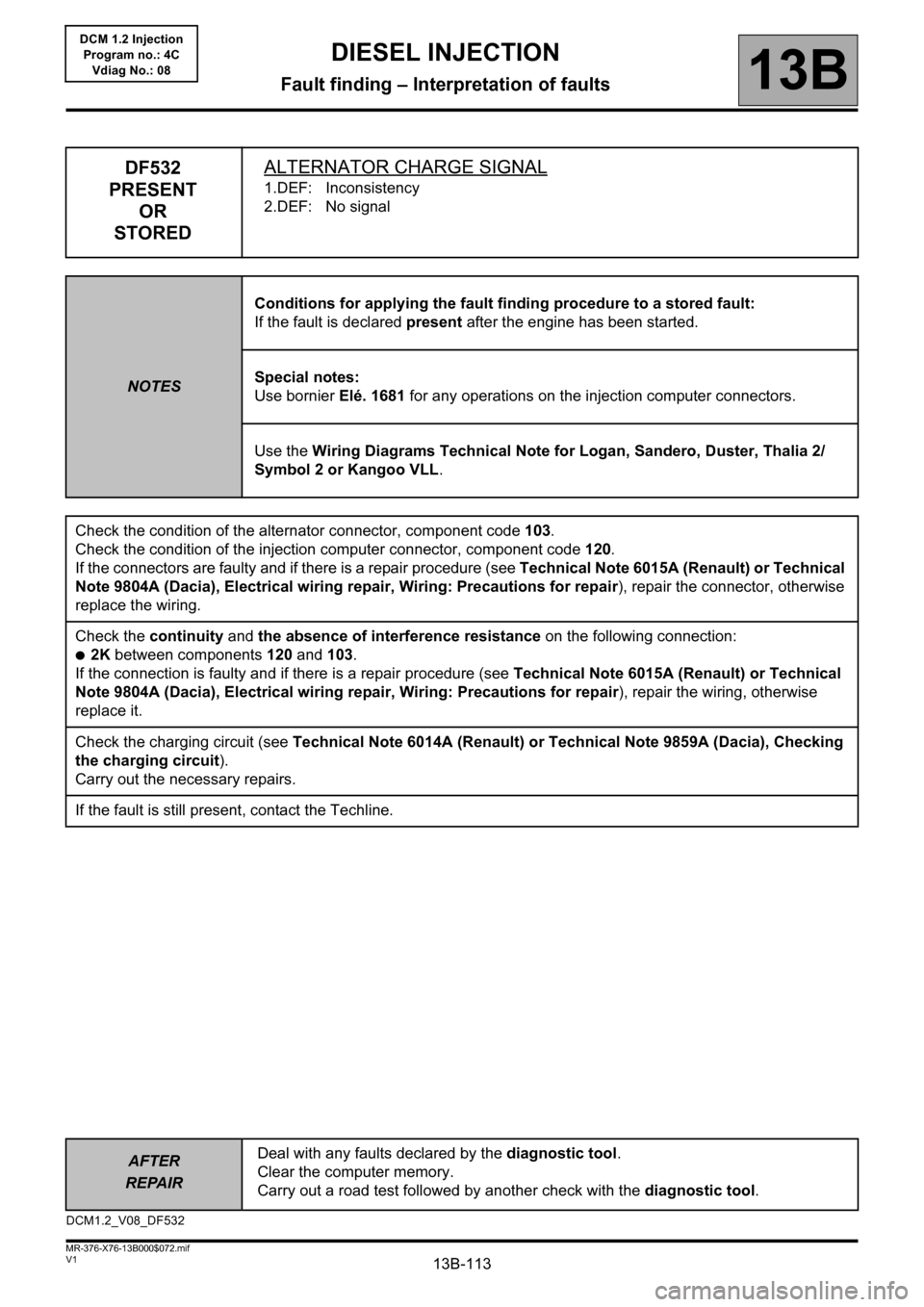
DF532
PRESENT
OR
STOREDALTERNATOR CHARGE SIGNAL
1.DEF: Inconsistency
2.DEF: No signal
NOTESConditions for applying the fault finding procedure to a stored fault:
If the fault is declared present after the engine has been started.
Special notes:
Use bornier Elé. 1681 for any operations on the injection computer connectors.
Use the Wiring Diagrams Technical Note for Logan, Sandero, Duster, Thalia 2/
Symbol 2 or Kangoo VLL.
Check the condition of the alternator connector, component code 103.
Check the condition of the injection computer connector, component code 120.
If the connectors are faulty and if there is a repair procedure (see Technical Note 6015A (Renault) or Technical
Note 9804A (Dacia), Electrical wiring repair, Wiring: Precautions for repair), repair the connector, otherwise
replace the wiring.
Check the continuity and the absence of interference resistance on the following connection:
●2K between components 120 and 103.
If the connection is faulty and if there is a repair procedure (see Technical Note 6015A (Renault) or Technical
Note 9804A (Dacia), Electrical wiring repair, Wiring: Precautions for repair), repair the wiring, otherwise
replace it.
Check the charging circuit (see Technical Note 6014A (Renault) or Technical Note 9859A (Dacia), Checking
the charging circuit).
Carry out the necessary repairs.
If the fault is still present, contact the Techline.
DCM1.2_V08_DF532
Page 114 of 204
13B-114
AFTER
REPAIRDeal with any faults declared by the diagnostic tool.
Clear the computer memory.
Carry out a road test followed by another check with the diagnostic tool.
V1 MR-376-X76-13B000$072.mif
DIESEL INJECTION
Fault finding – Interpretation of faults13B
DCM 1.2 Injection
Program no.: 4C
Vdiag No.: 08
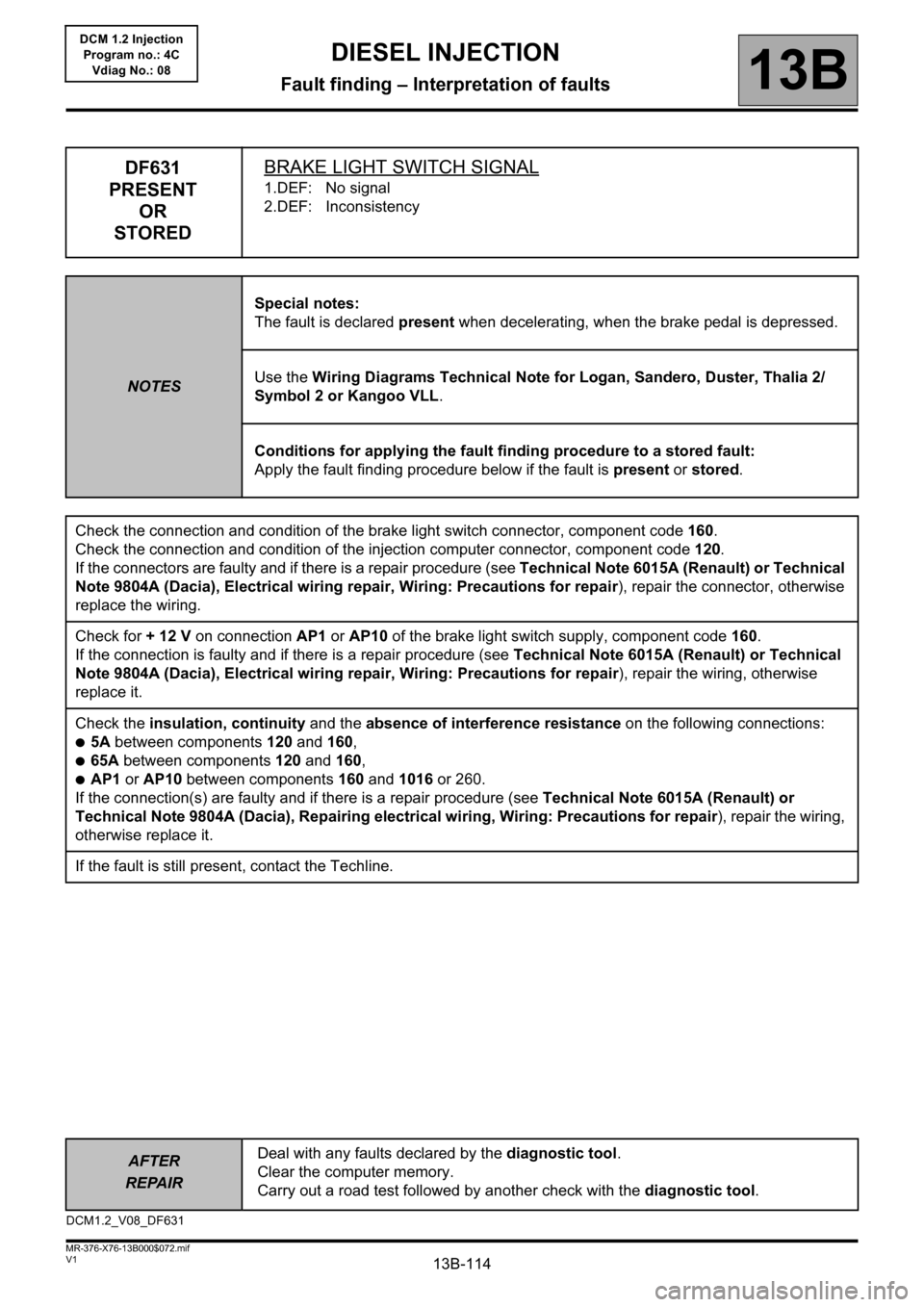
DF631
PRESENT
OR
STOREDBRAKE LIGHT SWITCH SIGNAL
1.DEF: No signal
2.DEF: Inconsistency
NOTESSpecial notes:
The fault is declared present when decelerating, when the brake pedal is depressed.
Use the Wiring Diagrams Technical Note for Logan, Sandero, Duster, Thalia 2/
Symbol 2 or Kangoo VLL.
Conditions for applying the fault finding procedure to a stored fault:
Apply the fault finding procedure below if the fault is present or stored.
Check the connection and condition of the brake light switch connector, component code160.
Check the connection and condition of the injection computer connector, component code 120.
If the connectors are faulty and if there is a repair procedure (see Technical Note 6015A (Renault) or Technical
Note 9804A (Dacia), Electrical wiring repair, Wiring: Precautions for repair), repair the connector, otherwise
replace the wiring.
Check for + 12 V on connection AP1 or AP10 of the brake light switch supply, component code 160.
If the connection is faulty and if there is a repair procedure (see Technical Note 6015A (Renault) or Technical
Note 9804A (Dacia), Electrical wiring repair, Wiring: Precautions for repair), repair the wiring, otherwise
replace it.
Check the insulation, continuity and the absence of interference resistance on the following connections:
●5A between components 120 and 160,
●65A between components 120 and 160,
●AP1 or AP10 between components 160 and 1016 or 260.
If the connection(s) are faulty and if there is a repair procedure (see Technical Note 6015A (Renault) or
Technical Note 9804A (Dacia), Repairing electrical wiring, Wiring: Precautions for repair), repair the wiring,
otherwise replace it.
If the fault is still present, contact the Techline.
DCM1.2_V08_DF631
Page 116 of 204
13B-116
AFTER
REPAIRDeal with any faults declared by the diagnostic tool.
Clear the computer memory.
Carry out a road test followed by another check with the diagnostic tool.
V1 MR-376-X76-13B000$072.mif
DIESEL INJECTION
Fault finding – Interpretation of faults13B
DCM 1.2 Injection
Program no.: 4C
Vdiag No.: 08
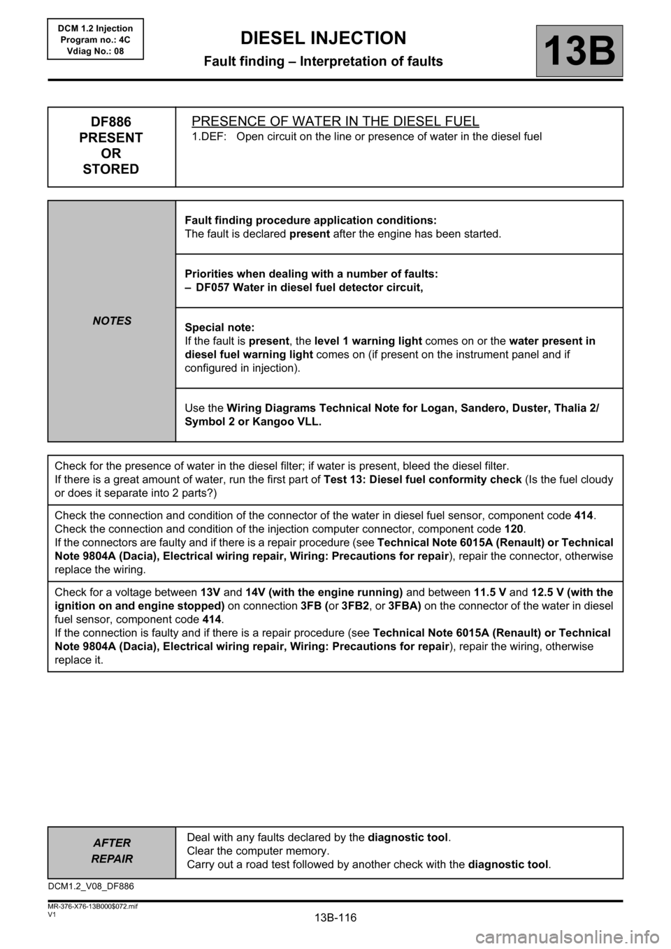
DF886
PRESENT
OR
STOREDPRESENCE OF WATER IN THE DIESEL FUEL
1.DEF: Open circuit on the line or presence of water in the diesel fuel
NOTESFault finding procedure application conditions:
The fault is declared present after the engine has been started.
Priorities when dealing with a number of faults:
– DF057 Water in diesel fuel detector circuit,
Special note:
If the fault is present, the level 1 warning light comes on or the water present in
diesel fuel warning light comes on (if present on the instrument panel and if
configured in injection).
Use the Wiring Diagrams Technical Note for Logan, Sandero, Duster, Thalia 2/
Symbol 2 or Kangoo VLL.
Check for the presence of water in the diesel filter; if water is present, bleed the diesel filter.
If there is a great amount of water, run the first part of Test 13: Diesel fuel conformity check (Is the fuel cloudy
or does it separate into 2 parts?)
Check the connection and condition of the connector of the water in diesel fuel sensor, component code 414.
Check the connection and condition of the injection computer connector, component code 120.
If the connectors are faulty and if there is a repair procedure (see Technical Note 6015A (Renault) or Technical
Note 9804A (Dacia), Electrical wiring repair, Wiring: Precautions for repair), repair the connector, otherwise
replace the wiring.
Check for a voltage between 13V and 14V (with the engine running) and between 11.5 V and 12.5 V (with the
ignition on and engine stopped) on connection 3FB (or 3FB2, or 3FBA) on the connector of the water in diesel
fuel sensor, component code 414.
If the connection is faulty and if there is a repair procedure (see Technical Note 6015A (Renault) or Technical
Note 9804A (Dacia), Electrical wiring repair, Wiring: Precautions for repair), repair the wiring, otherwise
replace it.
DCM1.2_V08_DF886
Page 118 of 204
13B-118
AFTER
REPAIRDeal with any faults declared by the diagnostic tool.
Clear the computer memory.
Carry out a road test followed by another check with the diagnostic tool.
V1 MR-376-X76-13B000$072.mif
DIESEL INJECTION
Fault finding – Interpretation of faults13B
DCM 1.2 Injection
Program no.: 4C
Vdiag No.: 08
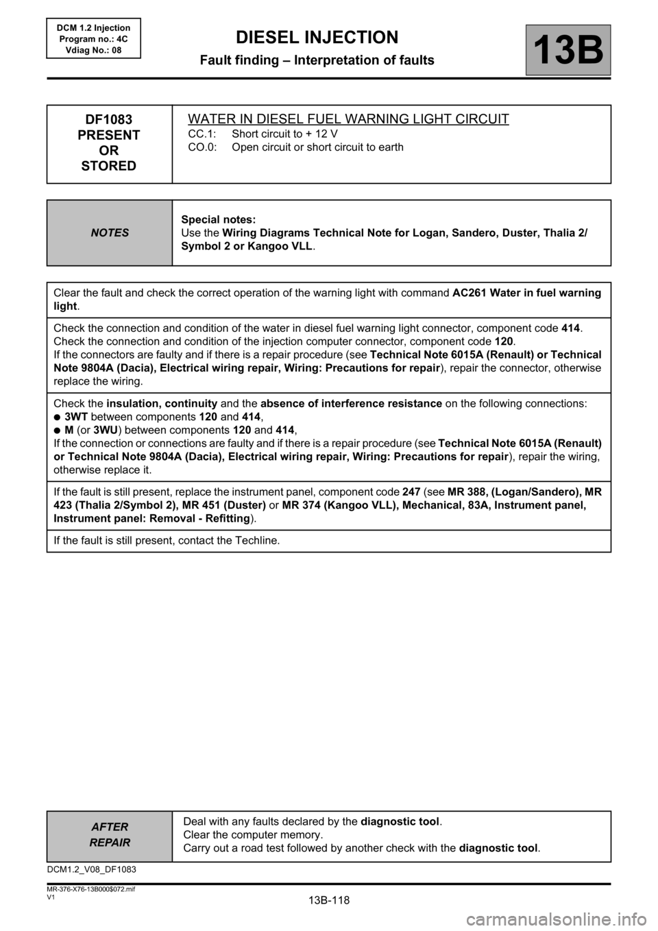
DF1083
PRESENT
OR
STOREDWATER IN DIESEL FUEL WARNING LIGHT CIRCUIT
CC.1: Short circuit to + 12 V
CO.0: Open circuit or short circuit to earth
NOTESSpecial notes:
Use the Wiring Diagrams Technical Note for Logan, Sandero, Duster, Thalia 2/
Symbol 2 or Kangoo VLL.
Clear the fault and check the correct operation of the warning light with command AC261 Water in fuel warning
light.
Check the connection and condition of the water in diesel fuel warning light connector, component code 414.
Check the connection and condition of the injection computer connector, component code 120.
If the connectors are faulty and if there is a repair procedure (see Technical Note 6015A (Renault) or Technical
Note 9804A (Dacia), Electrical wiring repair, Wiring: Precautions for repair), repair the connector, otherwise
replace the wiring.
Check the insulation, continuity and the absence of interference resistance on the following connections:
●3WT between components 120 and 414,
●M (or 3WU) between components 120 and 414,
If the connection or connections are faulty and if there is a repair procedure (see Technical Note 6015A (Renault)
or Technical Note 9804A (Dacia), Electrical wiring repair, Wiring: Precautions for repair), repair the wiring,
otherwise replace it.
If the fault is still present, replace the instrument panel, component code 247 (see MR 388, (Logan/Sandero), MR
423 (Thalia 2/Symbol 2), MR 451 (Duster) or MR 374 (Kangoo VLL), Mechanical, 83A, Instrument panel,
Instrument panel: Removal - Refitting).
If the fault is still present, contact the Techline.
DCM1.2_V08_DF1083
Page 136 of 204
13B-136
AFTER REPAIRDeal with any faults. Clear the faults from the computer memory.
Switch off the ignition and carry out a road test followed by a test with the diagnostic
tool.
V1 MR-376-X76-13B000$100.mif
13B
DCM 1.2 Injection
Program no.: 4C
Vdiag No.: 08
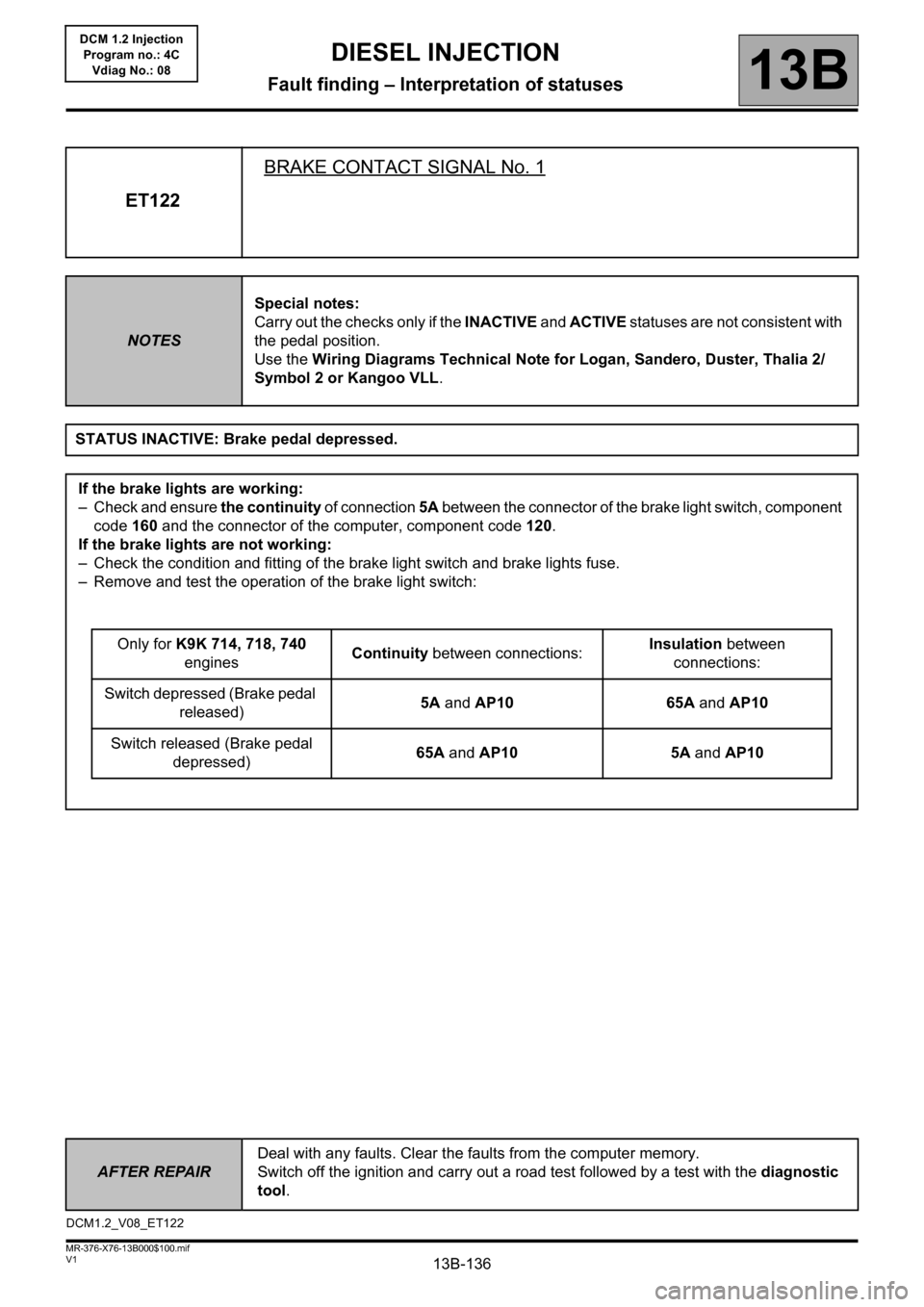
ET122BRAKE CONTACT SIGNAL No. 1
NOTESSpecial notes:
Carry out the checks only if the INACTIVE and ACTIVE statuses are not consistent with
the pedal position.
Use the Wiring Diagrams Technical Note for Logan, Sandero, Duster, Thalia 2/
Symbol 2 or Kangoo VLL.
STATUS INACTIVE: Brake pedal depressed.
If the brake lights are working:
– Check and ensure the continuity of connection 5A between the connector of the brake light switch, component
code 160 and the connector of the computer, component code 120.
If the brake lights are not working:
– Check the condition and fitting of the brake light switch and brake lights fuse.
– Remove and test the operation of the brake light switch:
Only for K9K 714, 718, 740
enginesContinuity between connections:Insulation between
connections:
Switch depressed (Brake pedal
released)5A and AP10 65A and AP10
Switch released (Brake pedal
depressed)65A and AP10 5A and AP10
DCM1.2_V08_ET122
DIESEL INJECTION
Fault finding – Interpretation of statuses
Page 139 of 204
13B-139
AFTER REPAIRDeal with any faults. Clear the faults from the computer memory.
Switch off the ignition and carry out a road test followed by a test with the diagnostic
tool.
V1 MR-376-X76-13B000$100.mif
DIESEL INJECTION
Fault finding – Interpretation of statuses13B
DCM 1.2 Injection
Program no.: 4C
Vdiag No.: 08
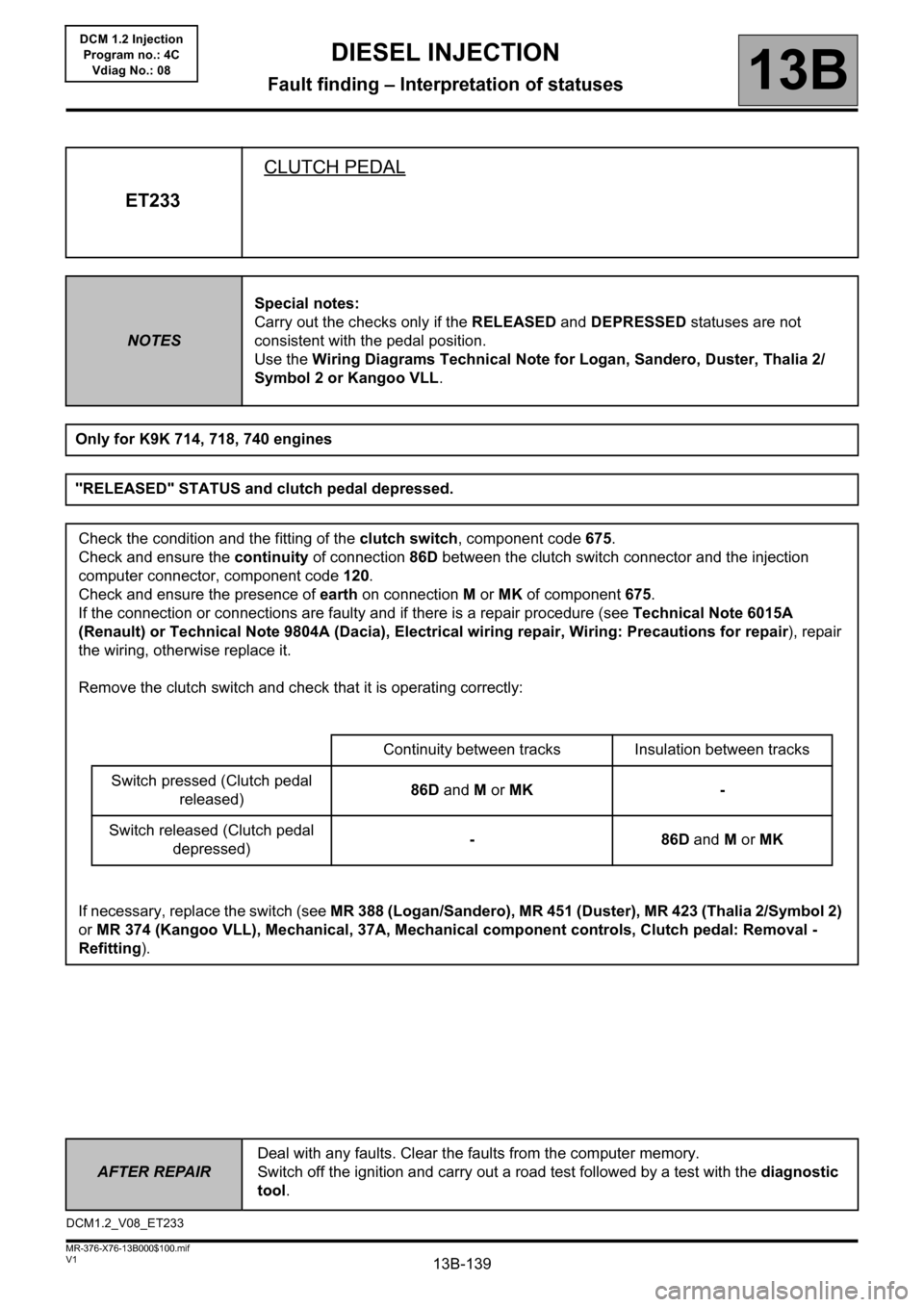
ET233CLUTCH PEDAL
NOTESSpecial notes:
Carry out the checks only if the RELEASED and DEPRESSED statuses are not
consistent with the pedal position.
Use the Wiring Diagrams Technical Note for Logan, Sandero, Duster, Thalia 2/
Symbol 2 or Kangoo VLL.
Only for K9K 714, 718, 740 engines
"RELEASED" STATUS and clutch pedal depressed.
Check the condition and the fitting of the clutch switch, component code 675.
Check and ensure the continuity of connection 86D between the clutch switch connector and the injection
computer connector, component code 120.
Check and ensure the presence of earth on connection M or MK of component 675.
If the connection or connections are faulty and if there is a repair procedure (see Technical Note 6015A
(Renault) or Technical Note 9804A (Dacia), Electrical wiring repair, Wiring: Precautions for repair), repair
the wiring, otherwise replace it.
Remove the clutch switch and check that it is operating correctly:
Continuity between tracks Insulation between tracks
Switch pressed (Clutch pedal
released)86D and M or MK -
Switch released (Clutch pedal
depressed)-86D and M or MK
If necessary, replace the switch (see MR 388 (Logan/Sandero), MR 451 (Duster), MR 423 (Thalia 2/Symbol 2)
or MR 374 (Kangoo VLL), Mechanical, 37A, Mechanical component controls, Clutch pedal: Removal -
Refitting).
DCM1.2_V08_ET233
Page 143 of 204
13B-143
AFTER REPAIRDeal with any faults displayed by the diagnostic tool.
Clear the computer memory.
Carry out a road test followed by another check with the diagnostic tool.
V1 MR-376-X76-13B000$120.mif
13B
DCM 1.2 Injection
Program no.: 4C
Vdiag No.: 08
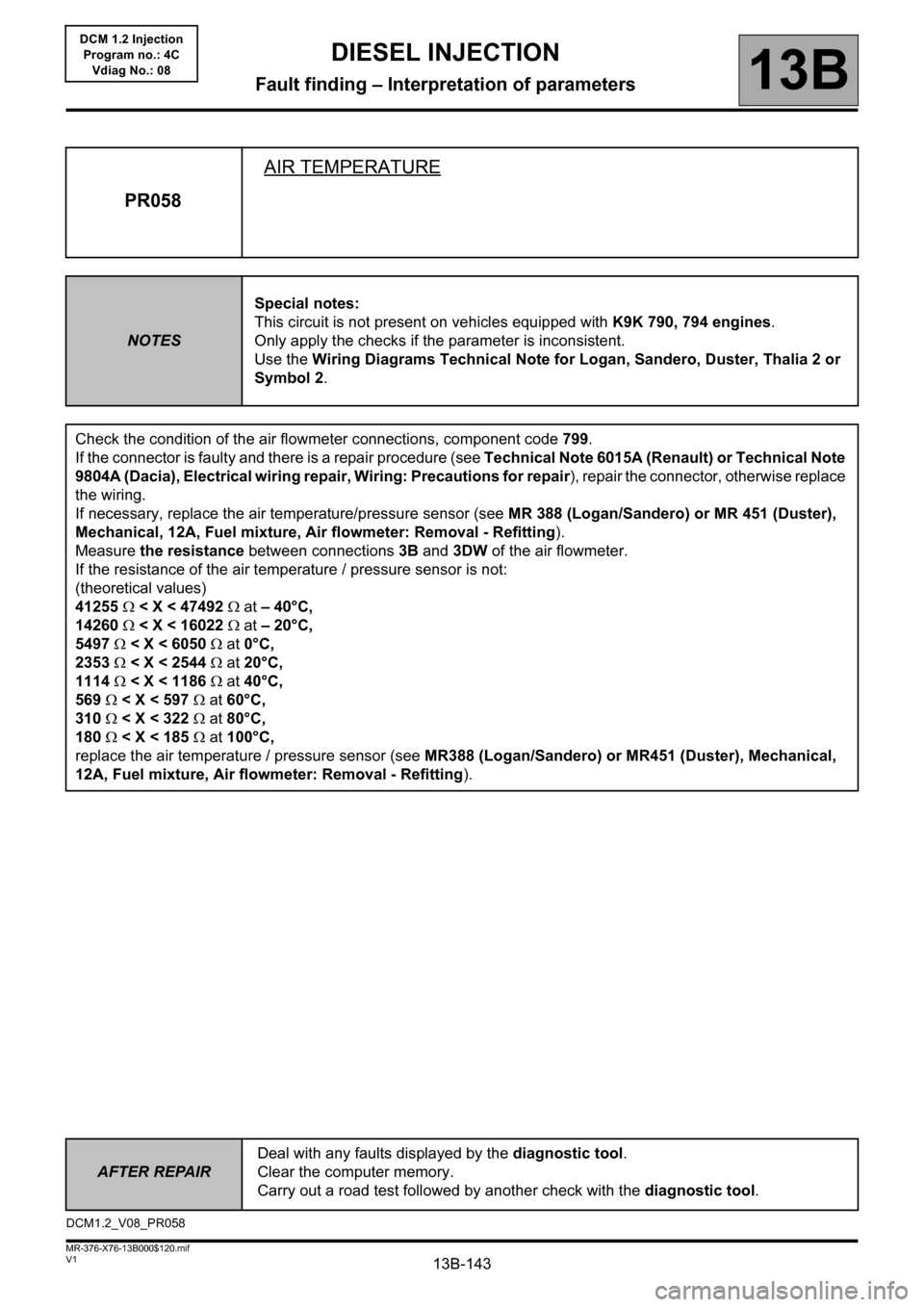
PR058AIR TEMPERATURE
NOTESSpecial notes:
This circuit is not present on vehicles equipped with K9K 790, 794 engines.
Only apply the checks if the parameter is inconsistent.
Use the Wiring Diagrams Technical Note for Logan, Sandero, Duster, Thalia 2 or
Symbol 2.
Check the condition of the air flowmeter connections, component code 799.
If the connector is faulty and there is a repair procedure (see Technical Note 6015A (Renault) or Technical Note
9804A (Dacia), Electrical wiring repair, Wiring: Precautions for repair), repair the connector, otherwise replace
the wiring.
If necessary, replace the air temperature/pressure sensor (see MR 388 (Logan/Sandero) or MR 451 (Duster),
Mechanical, 12A, Fuel mixture, Air flowmeter: Removal - Refitting).
Measure the resistance between connections 3B and 3DW of the air flowmeter.
If the resistance of the air temperature / pressure sensor is not:
(theoretical values)
41255 < X < 47492 at – 40°C,
14260 < X < 16022 at – 20°C,
5497 < X < 6050 at 0°C,
2353 < X < 2544 at 20°C,
1114 < X < 1186 at 40°C,
569 < X < 597 at 60°C,
310 < X < 322 at 80°C,
180 < X < 185 at 100°C,
replace the air temperature / pressure sensor (see MR388 (Logan/Sandero) or MR451 (Duster), Mechanical,
12A, Fuel mixture, Air flowmeter: Removal - Refitting).
DCM1.2_V08_PR058
DIESEL INJECTION
Fault finding – Interpretation of parameters
Page 144 of 204
13B-144
AFTER REPAIRDeal with any faults displayed by the diagnostic tool.
Clear the computer memory.
Carry out a road test followed by another check with the diagnostic tool.
V1 MR-376-X76-13B000$120.mif
DIESEL INJECTION
Fault finding – Interpretation of parameters13B
DCM 1.2 Injection
Program no.: 4C
Vdiag No.: 08
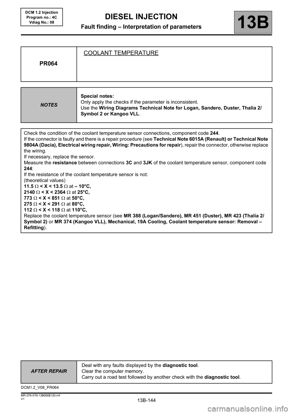
PR064COOLANT TEMPERATURE
NOTESSpecial notes:
Only apply the checks if the parameter is inconsistent.
Use the Wiring Diagrams Technical Note for Logan, Sandero, Duster, Thalia 2/
Symbol 2 or Kangoo VLL.
Check the condition of the coolant temperature sensor connections, component code 244.
If the connector is faulty and there is a repair procedure (see Technical Note 6015A (Renault) or Technical Note
9804A (Dacia), Electrical wiring repair, Wiring: Precautions for repair), repair the connector, otherwise replace
the wiring.
If necessary, replace the sensor.
Measure the resistance between connections 3C and 3JK of the coolant temperature sensor, component code
244:
If the resistance of the coolant temperature sensor is not:
(theoretical values)
11.5 < X < 13.5 at – 10°C,
2140 < X < 2364 at 25°C,
773 < X < 851 at 50°C,
275 < X < 291 at 80°C,
112 < X < 118 at 110°C,
Replace the coolant temperature sensor (see MR 388 (Logan/Sandero), MR 451 (Duster), MR 423 (Thalia 2/
Symbol 2) or MR 374 (Kangoo VLL), Mechanical, 19A Cooling, Coolant temperature sensor: Removal –
Refitting).
DCM1.2_V08_PR064