Air con RENAULT KANGOO 2013 X61 / 2.G Diesel DCM 1.2 Injection Workshop Manual
[x] Cancel search | Manufacturer: RENAULT, Model Year: 2013, Model line: KANGOO, Model: RENAULT KANGOO 2013 X61 / 2.GPages: 204, PDF Size: 0.99 MB
Page 1 of 204
1Engine and peripherals
V1 MR-376-X76-13B000$TOC.mif
V1
13B
"The repair procedures given by the manufacturer in this document are based on the
technical specifications current when it was prepared.
The procedures may be modified as a result of changes introduced by the
manufacturer in the production of the various component units and accessories from
which his vehicles are constructed."
V1
All rights reserved by Renault s.a.s.
Edition Anglaise
Copying or translating, in part or in full, of this document or use of the service part
reference numbering system is forbidden without the prior written authority of
Renault s.a.s.
© Renault s.a.s. 2013
DIESEL INJECTION
DCM 1.2 Injection
Program no.: 4C
Vdiag No.: 08
Fault finding – Introduction 13B - 2
Fault finding – Cleanliness guidelines 13B - 7
Fault finding – System operation 13B - 10
Fault finding – Replacement of components 13B - 17
Fault finding – Configurations and programming 13B - 21
Fault finding – Fault summary table 13B - 22
Fault finding – Interpretation of faults 13B - 25
Fault finding – Conformity check 13B - 119
Fault finding – Status summary table 13B - 135
Fault finding – Interpretation of statuses 13B - 136
Fault finding – Parameter summary table 13B - 141
Fault finding – Interpretation of parameters 13B - 143
Fault finding – Command summary table 13B - 145
Fault finding – Customer complaints 13B - 148
Fault finding – Fault Finding Chart 13B - 150
Fault finding – Tests 13B - 186
Page 3 of 204
13B-3V1 MR-376-X76-13B000$010.mif
DIESEL INJECTION
Fault finding – Introduction13B
DCM 1.2 Injection
Program no.: 4C
Vdiag No.: 08
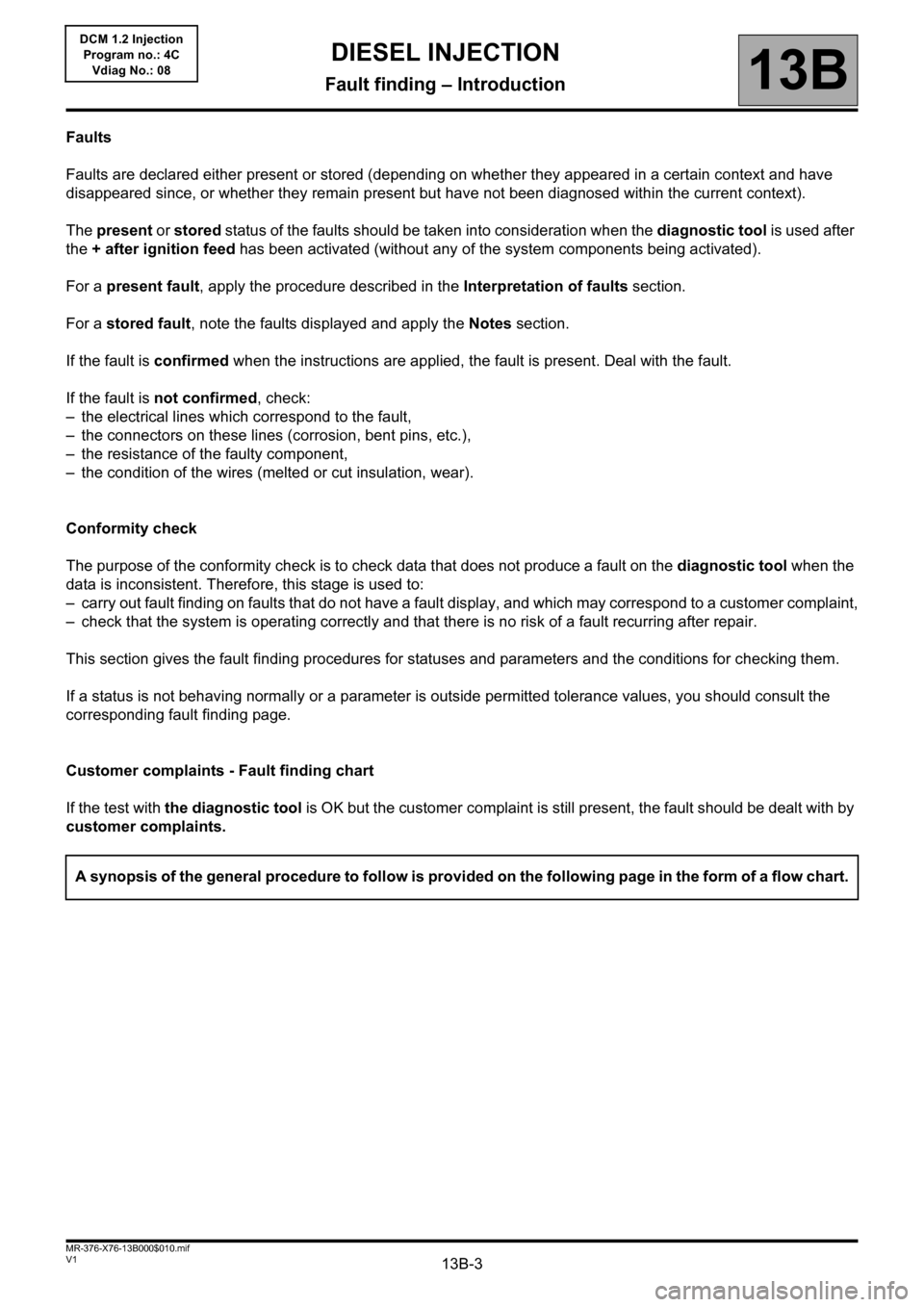
Faults
Faults are declared either present or stored (depending on whether they appeared in a certain context and have
disappeared since, or whether they remain present but have not been diagnosed within the current context).
The present or stored status of the faults should be taken into consideration when the diagnostic tool is used after
the + after ignition feed has been activated (without any of the system components being activated).
For a present fault, apply the procedure described in the Interpretation of faults section.
For a stored fault, note the faults displayed and apply the Notes section.
If the fault is confirmed when the instructions are applied, the fault is present. Deal with the fault.
If the fault is not confirmed, check:
– the electrical lines which correspond to the fault,
– the connectors on these lines (corrosion, bent pins, etc.),
– the resistance of the faulty component,
– the condition of the wires (melted or cut insulation, wear).
Conformity check
The purpose of the conformity check is to check data that does not produce a fault on the diagnostic tool when the
data is inconsistent. Therefore, this stage is used to:
– carry out fault finding on faults that do not have a fault display, and which may correspond to a customer complaint,
– check that the system is operating correctly and that there is no risk of a fault recurring after repair.
This section gives the fault finding procedures for statuses and parameters and the conditions for checking them.
If a status is not behaving normally or a parameter is outside permitted tolerance values, you should consult the
corresponding fault finding page.
Customer complaints - Fault finding chart
If the test with the diagnostic tool is OK but the customer complaint is still present, the fault should be dealt with by
customer complaints.
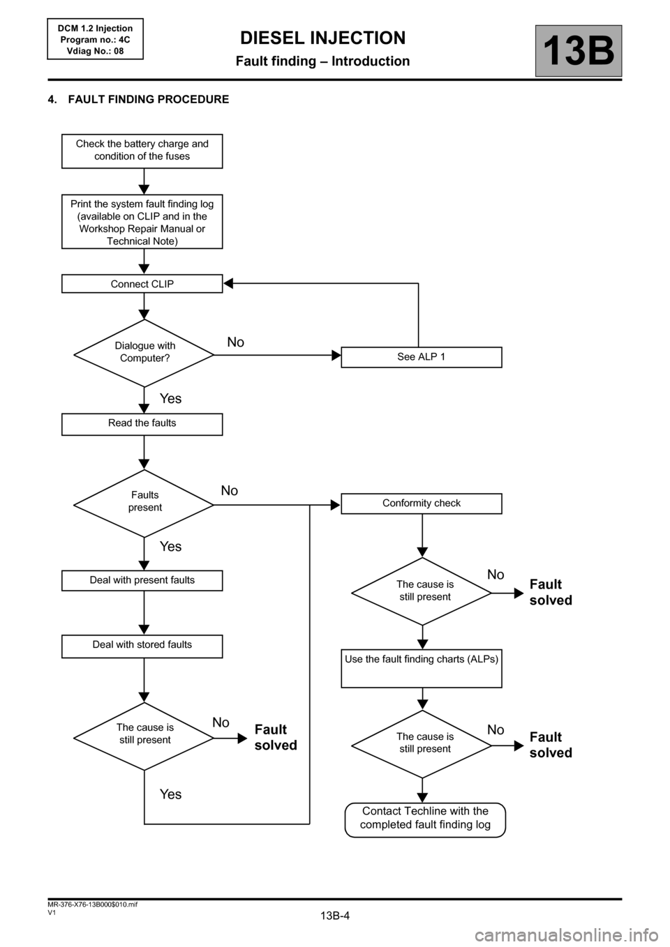
A synopsis of the general procedure to follow is provided on the following page in the form of a flow chart.
Page 4 of 204
13B-4V1 MR-376-X76-13B000$010.mif
DIESEL INJECTION
Fault finding – Introduction13B
DCM 1.2 Injection
Program no.: 4C
Vdiag No.: 08
4. FAULT FINDING PROCEDURE
Check the battery charge and
condition of the fuses
Print the system fault finding log
(available on CLIP and in the
Workshop Repair Manual or
Technical Note)
Connect CLIP
See ALP 1
Read the faults
Deal with present faults
Deal with stored faults
Conformity check
Use the fault finding charts (ALPs)
Dialogue with
Computer?
Faults
present
The cause is
still present
The cause is
still presentThe cause is
still present
Contact Techline with the
completed fault finding log
No
NoNo
No No
Ye s
Ye s
Ye sFault
solvedFault
solved Fault
solved
Page 5 of 204
13B-5V1 MR-376-X76-13B000$010.mif
DIESEL INJECTION
Fault finding – Introduction13B
DCM 1.2 Injection
Program no.: 4C
Vdiag No.: 08
4. FAULT FINDING PROCEDURE (continued)
Wiring check
Fault finding problems
Disconnecting the connectors and/or manipulating the wiring may temporarily clear the cause of a fault.
Electrical measurements of voltage, resistance and insulation are generally correct, especially if the fault is not
present when the analysis is made (stored fault).
Visual inspection
Look for damage under the bonnet and in the passenger compartment.
Carefully check the fuses, insulators and wiring harness routing.
Look for signs of oxidation.
Physical inspection
When handling the wiring, use the diagnostic tool to detect any change in the status of the faults from "stored" to
"present".
Make sure that the connectors are firmly secured.
Apply light pressure to the connectors.
Twist the wiring harness.
If there is a change in status, try to locate the source of the fault.
Inspection of each component
Disconnect the connectors and check the appearance of the clips and tabs, as well as the crimping (no crimping on
the insulating section).
Make sure that the clips and tabs are properly locked in the sockets.
Check that the clips or tabs have not been bent back during connection.
Check the clip contact pressure using an appropriate model of tab.
Resistance check
Check the continuity of entire lines, then section by section.
Look for a short circuit to earth, to + 12 V or with another wire.
If a fault is detected, repair or replace the wiring harness.
Page 7 of 204
13B-7V1 MR-376-X76-13B000$020.mif
13B
DCM 1.2 Injection
Program no.: 4C
Vdiag No.: 08
I - RISKS ASSOCIATED WITH CONTAMINATION
The high pressure direct injection system is highly sensitive to contamination. The risks caused by the introduction
of contamination are:
– damage to or destruction of the high pressure injection system,
– a component seizing up,
– a component losing its sealing.
All After-Sales operations must be performed under very clean conditions. This means that no impurities
(particles a few microns in size) should have penetrated the system during dismantling.
The cleanliness guidelines must be applied from the filter through to the injectors.
What are the sources of contamination?
– metal or plastic chips,
– paint,
–fibres:
– from cardboard,
– from brushes,
– from paper,
– from clothing,
–from cloths,
– foreign bodies such as hair,
– the ambient atmosphere,
–etc.
IMPORTANT
Cleaning the engine using a high pressure washer is prohibited because of the risk of damaging connections. In
addition, moisture may collect in the connectors and create faults in the electrical connections.
DIESEL INJECTION
Fault finding – Cleanliness guidelines
Page 8 of 204
13B-8V1 MR-376-X76-13B000$020.mif
DIESEL INJECTION
Fault finding – Cleanliness guidelines13B
DCM 1.2 Injection
Program no.: 4C
Vdiag No.: 08
II - INSTRUCTIONS TO BE FOLLOWED BEFORE CARRYING OUT ANY WORK
Ensure that you have plugs for the unions to be opened (set of plugs available from the Parts Department). Plugs
are to be used only once. They must be discarded after use (once used they are soiled and cleaning is not sufficient
to make them reusable). Unused plugs must be thrown away.
Ensure that you have hermetically resealable plastic bags for storing removed parts. Parts stored in this way will be
less susceptible to the risk of contamination. The bags are to be used once only, and discarded after use.
Use lint-free cleaning cloths (cloth part reference 77 11 211 707). The use of ordinary cloth or paper is not permitted.
They are not lint-free and could contaminate the fuel circuit. A lint-free cloth should only be used once.
Use fresh cleaning agent for each operation (used cleaning agent is contaminated). Pour it into a clean receptacle.
For each operation, use a clean brush in good condition (the brush must not shed its bristles).
Use a brush and cleaning agent to clean the unions to be opened.
Blow compressed air over the cleaned parts (tools, workbench, the parts, unions and injection system zones).
Check that no bristles are left.
Wash your hands before and during the operation if necessary.
When wearing leather protective gloves cover them with latex gloves to prevent contamination.IMPORTANT
Before carrying out any work on the high pressure injection system, protect:
– the accessories belts,
– the electrical accessories, (starter, alternator, electric power-assisted steering pump),
– the flywheel surface, to prevent any diesel from running onto the clutch friction plate.
– timing chain
Page 9 of 204
13B-9V1 MR-376-X76-13B000$020.mif
DIESEL INJECTION
Fault finding – Cleanliness guidelines13B
DCM 1.2 Injection
Program no.: 4C
Vdiag No.: 08
III - INSTRUCTIONS TO BE FOLLOWED DURING THE OPERATION
As soon as the circuit is open, all openings must be plugged to prevent impurities from entering the system.
The plugs to be used are available from the Parts Department. The plugs must not be reused under any
circumstances.
Seal the pouch shut, even if it has to be opened shortly afterwards. The ambient atmosphere carries contamination.
All components removed from the injection system must be stored in a hermetically-sealed plastic bag once
the plugs have been inserted.
Using a brush, cleaning agent, air gun, brush or normal cloth is strictly prohibited once the circuit has been opened.
These items could allow contamination to enter the system.
A new component replacing an old one must not be removed from its packaging until it is to be fitted to the vehicle.
Page 10 of 204
13B-10V1 MR-376-X76-13B000$030.mif
13B
DCM 1.2 Injection
Program no.: 4C
Vdiag No.: 08
System outline
The DCM 1.2 injection system used on the K9K engine is an electronically-managed high pressure injection system.
The fuel is compressed by a high pressure pump then stored in a rail that feeds the injectors. Injection takes place
when a current pulse is applied to the injector holders.
The amount injected is proportional to the rail pressure and the applied pulse length, and the start of injection is
synchronised with the start of the pulse.
The system includes two subsystems, which have different fuel pressure levels:
– the low pressure circuit contains the tank, the diesel fuel filter, the transfer pump and the injector holder return pipes,
– the high pressure circuit contains the high pressure pump, the rail, the injector holders and the high pressure pipes.
The injection system contains a number of sensors and actuators for controlling and monitoring the entire system.
Functions provided
Function: Fuel supply management (timing, flow and pressure).
Quantity of fuel injected and injection timing setting
The injection checking parameters are the quantities to be injected and their respective timing.
These are calculated by the computer using signals from the following sensors:
– Engine speed (Crankshaft +Cam for synchronisation).
– Accelerator pedal.
– Turbocharging pressure and air temperature (Turbocharger pressure).
– Coolant temperature.
– Air temperature.
– Air charge (Flow and Pressure).
– Pressure in the rail.
The quantities to be injected and their respective timing are converted into:
– a reference tooth,
– the time between this tooth and the start of the pulse,
– the time for which the supply to the injector holder is on.
Each injector holder is controlled by an electrical current which is sent according to previously calculated data. The
system makes one or two injections (one pilot injection, one main injection).
The general principle is to calculate an overall injected flow, which is then divided into the main injection flow and a
pilot injection flow to promote correct combustion and help reduce pollutant emissions.
DIESEL INJECTION
Fault finding – System operation
Page 12 of 204
13B-12V1 MR-376-X76-13B000$030.mif
DIESEL INJECTION
Fault finding – System operation13B
DCM 1.2 Injection
Program no.: 4C
Vdiag No.: 08
Idling speed regulation
The computer handles the calculation of idling speed. This has to take account of the instantaneous power level to
be supplied, according to the following factors:
– engine coolant temperature,
– gear ratio engaged,
– battery charge,
– electrical consumers (Additional heating, Air conditioning, Fan Unit, electric windows, etc.) active or inactive,
– system faults detected.
Individual injector correction (C2I)
The DCM 1.2 system injectors must be calibrated with correction values so that their flow may be adjusted precisely.
Each injector is calibrated for different pressures on a test bench, and its specifications are shown on a label
attached to the body of the injector holders. These individual correction values are then entered into the computer
EEPROM, which can then control the injectors, taking their manufacturing variations into account.
Measuring the angular position (Cylinder reference sensor)
The angular position is measured using a magneto-inductive sensor triggered by machined teeth on the shaft
flywheel. This flywheel has sixty teeth separated by six degrees minus two missing teeth, that form a notch.
A second sensor (Hall effect) triggered by a machined tooth on the high pressure pump drive pulley (synchronised
with the camshaft), which rotates at half the engine speed, supplies an injection cycle running signal. By comparing
the signals from these two sensors, the computer's APS module (Angular Position Subsystem) is able to supply the
synchronisation components to the system assembly, namely:
– the angular position of the flywheel
– the speed and number of the active injector
– the injection cycle progress.
This module also supplies the system with the engine speed signal.
Flow capacity function (VLC)
Because of the combination of several parameters such as the diesel fuel temperature, part wear, clogging of the
diesel filter etc., the system limit may be reached during its service life. If this happens, the rail pressure cannot be
maintained because the pump lacks the necessary capacity. If the pump lacks the necessary capacity, this
programming will therefore reduce the requested flow to a value that will enable the pressure monitoring system to
control the pressure again.
The customer may have noticed a loss of vehicle performance when this program is activated (confirmed by status
Flow capacity function). This is part of normal operation.
Page 13 of 204
13B-13V1 MR-376-X76-13B000$030.mif
DIESEL INJECTION
Fault finding – System operation13B
DCM 1.2 Injection
Program no.: 4C
Vdiag No.: 08
Function: Air flow management
EGR valve control
The EGR system (Exhaust gas recirculation) comprises a proportional EGR valve, with a built-in valve position
feedback potentiometer. The EGR valve position is controlled by the potentiometer in a closed loop and/or by
changes in the estimated air flow.
Special feature of the K9K796 Euro 2 engine (Indonesia): The EGR solenoid valve is present on the vehicle, but not
used. It always remains closed. It must not be replaced on this vehicle (unless there is a mechanical fault).
Calculating the air flow
K9K 790 and 794 engines are not fitted with an air flowmeter. Instead, the amount of fresh inlet air is evaluated
based on the values supplied by the surrounding systems.
The (theoretical) air load is calculated using a model with various calculation parameters, which are:
– the inlet air temperature measured by a sensor located after the turbocharger and/or after the exchanger (if fitted),
– the turbocharging pressure,
– the atmospheric pressure (external air),
– the EGR valve position,
– the fuel flow,
– the engine speed.
The atmospheric pressure sensor is optional. If fitted, it sends back a signal relating to the atmospheric pressure to
an analogue port on the micro-controller. If not, atmospheric pressure is recovered based on the turbocharger
pressure and the engine field.
For K9K 792 and 796 engines, the flow of fresh air entering the engine is measured by a hot-wire ratiometric sensor.
This flowmeter is used to manage the amount of exhaust gas to be recirculated to ensure optimum recirculation
rates. A fresh air temperature sensor is integrated into the flowmeter. Air flow measurement allows closed-loop
control via the EGR valve.
Turbocharger control
K9K 796 engine:
The turbocharging system is made up of a solenoid valve which is used to control the wastegate to adjust the
absolute pressure of the inlet circuit.
K9K 790, 792, 794 engines:
The turbocharger system is controlled by the inlet pressure and does not need to be controlled by the computer.
Pre-postheating actuation
Pre-postheating actuation consists of controlling the heater plugs and the preheating warning light on the instrument
panel. The heater plugs are activated by a preheating unit (controlled by the injection computer), and the power is
supplied by the battery. After the ignition is switched on a preheating delay is activated. The indicator light comes on
for the activation period which is dependent on the battery voltage, atmospheric pressure and coolant temperature.
If the temperature is below a certain threshold, a postheating function can be used to improve the combustion
stability, and consequently engine operation (reducing unburnt particles and pollutant emissions).