accelerator RENAULT KANGOO 2013 X61 / 2.G Diesel DCM 1.2 Injection Workshop Manual
[x] Cancel search | Manufacturer: RENAULT, Model Year: 2013, Model line: KANGOO, Model: RENAULT KANGOO 2013 X61 / 2.GPages: 204, PDF Size: 0.99 MB
Page 10 of 204
13B-10V1 MR-376-X76-13B000$030.mif
13B
DCM 1.2 Injection
Program no.: 4C
Vdiag No.: 08
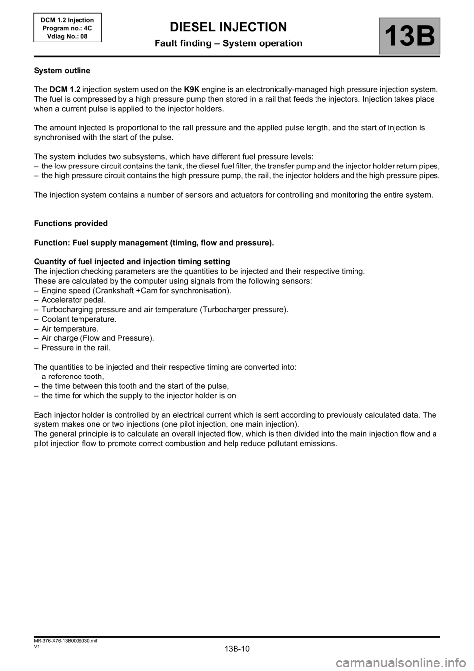
System outline
The DCM 1.2 injection system used on the K9K engine is an electronically-managed high pressure injection system.
The fuel is compressed by a high pressure pump then stored in a rail that feeds the injectors. Injection takes place
when a current pulse is applied to the injector holders.
The amount injected is proportional to the rail pressure and the applied pulse length, and the start of injection is
synchronised with the start of the pulse.
The system includes two subsystems, which have different fuel pressure levels:
– the low pressure circuit contains the tank, the diesel fuel filter, the transfer pump and the injector holder return pipes,
– the high pressure circuit contains the high pressure pump, the rail, the injector holders and the high pressure pipes.
The injection system contains a number of sensors and actuators for controlling and monitoring the entire system.
Functions provided
Function: Fuel supply management (timing, flow and pressure).
Quantity of fuel injected and injection timing setting
The injection checking parameters are the quantities to be injected and their respective timing.
These are calculated by the computer using signals from the following sensors:
– Engine speed (Crankshaft +Cam for synchronisation).
– Accelerator pedal.
– Turbocharging pressure and air temperature (Turbocharger pressure).
– Coolant temperature.
– Air temperature.
– Air charge (Flow and Pressure).
– Pressure in the rail.
The quantities to be injected and their respective timing are converted into:
– a reference tooth,
– the time between this tooth and the start of the pulse,
– the time for which the supply to the injector holder is on.
Each injector holder is controlled by an electrical current which is sent according to previously calculated data. The
system makes one or two injections (one pilot injection, one main injection).
The general principle is to calculate an overall injected flow, which is then divided into the main injection flow and a
pilot injection flow to promote correct combustion and help reduce pollutant emissions.
DIESEL INJECTION
Fault finding – System operation
Page 31 of 204
13B-31
AFTER REPAIRDeal with any faults declared by the diagnostic tool.
Clear the computer memory.
Carry out a road test followed by another check with the diagnostic tool.
V1 MR-376-X76-13B000$071.mif
DIESEL INJECTION
Fault finding – Interpretation of faults13B
DCM 1.2 Injection
Program no.: 4C
Vdiag No.: 08
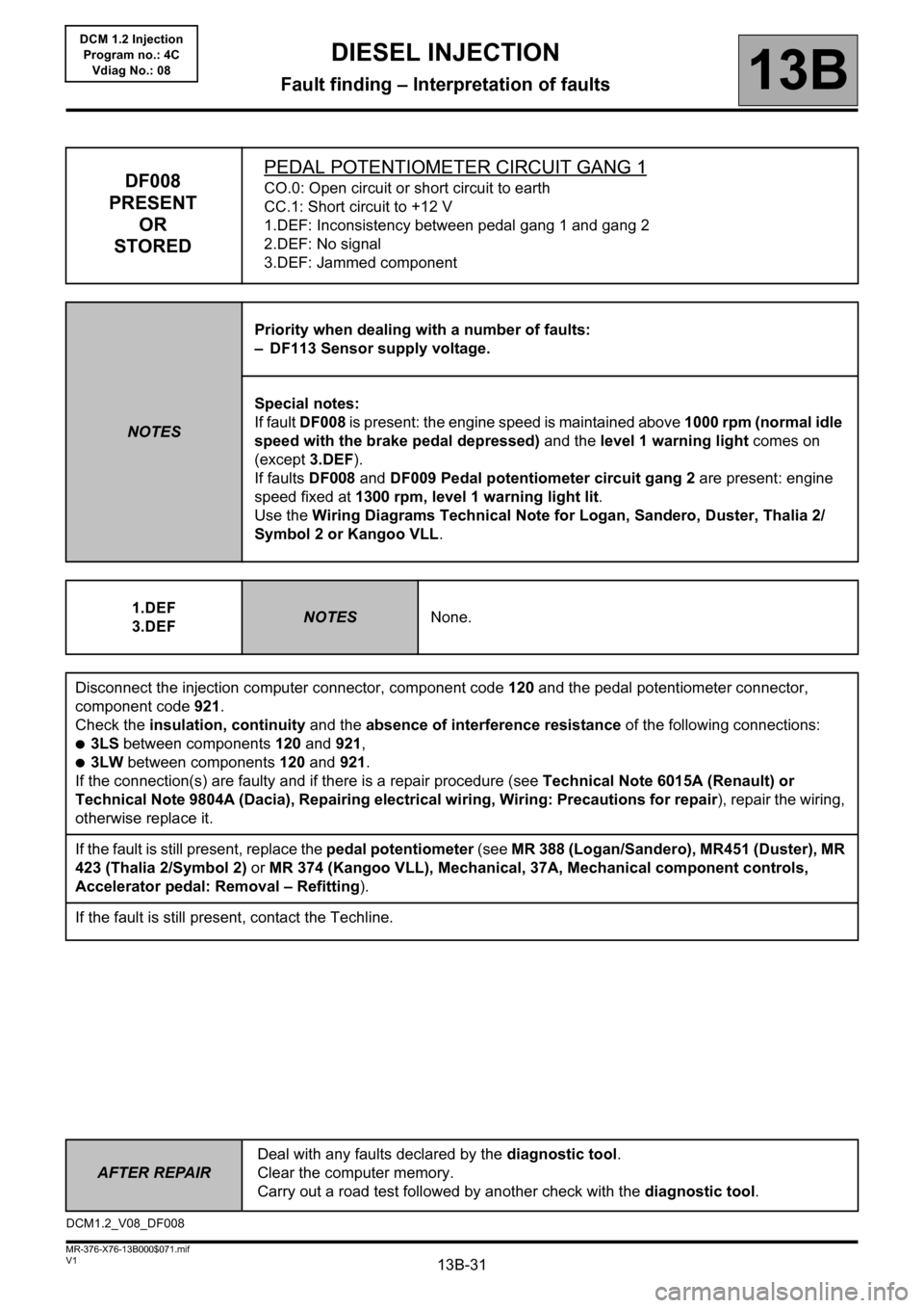
DF008
PRESENT
OR
STOREDPEDAL POTENTIOMETER CIRCUIT GANG 1CO.0: Open circuit or short circuit to earth
CC.1: Short circuit to +12 V
1.DEF: Inconsistency between pedal gang 1 and gang 2
2.DEF: No signal
3.DEF: Jammed component
NOTESPriority when dealing with a number of faults:
– DF113 Sensor supply voltage.
Special notes:
If fault DF008 is present: the engine speed is maintained above 1000 rpm (normal idle
speed with the brake pedal depressed) and the level 1 warning light comes on
(except 3.DEF).
If faults DF008 and DF009 Pedal potentiometer circuit gang 2 are present: engine
speed fixed at 1300 rpm, level 1 warning light lit.
Use the Wiring Diagrams Technical Note for Logan, Sandero, Duster, Thalia 2/
Symbol 2 or Kangoo VLL.
1.DEF
3.DEF
NOTESNone.
Disconnect the injection computer connector, component code 120 and the pedal potentiometer connector,
component code 921.
Check the insulation, continuity and the absence of interference resistance of the following connections:
●3LS between components 120 and 921,
●3LW between components 120 and 921.
If the connection(s) are faulty and if there is a repair procedure (see Technical Note 6015A (Renault) or
Technical Note 9804A (Dacia), Repairing electrical wiring, Wiring: Precautions for repair), repair the wiring,
otherwise replace it.
If the fault is still present, replace the pedal potentiometer (see MR 388 (Logan/Sandero), MR451 (Duster), MR
423 (Thalia 2/Symbol 2) or MR 374 (Kangoo VLL), Mechanical, 37A, Mechanical component controls,
Accelerator pedal: Removal – Refitting).
If the fault is still present, contact the Techline.
DCM1.2_V08_DF008
Page 33 of 204
13B-33
AFTER REPAIRDeal with any faults declared by the diagnostic tool.
Clear the computer memory.
Carry out a road test followed by another check with the diagnostic tool.
V1 MR-376-X76-13B000$071.mif
DIESEL INJECTION
Fault finding – Interpretation of faults13B
DCM 1.2 Injection
Program no.: 4C
Vdiag No.: 08
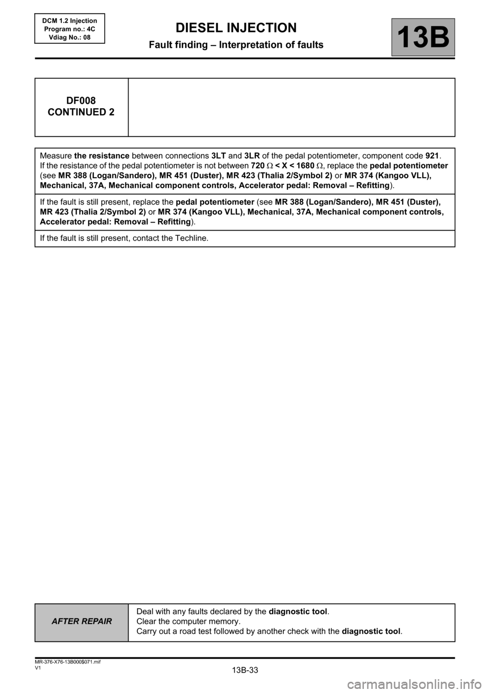
DF008
CONTINUED 2
Measure the resistance between connections 3LT and 3LR of the pedal potentiometer, component code 921.
If the resistance of the pedal potentiometer is not between 720 < X < 1680 , replace the pedal potentiometer
(see MR 388 (Logan/Sandero), MR 451 (Duster), MR 423 (Thalia 2/Symbol 2) or MR 374 (Kangoo VLL),
Mechanical, 37A, Mechanical component controls, Accelerator pedal: Removal – Refitting).
If the fault is still present, replace the pedal potentiometer (see MR 388 (Logan/Sandero), MR 451 (Duster),
MR 423 (Thalia 2/Symbol 2) or MR 374 (Kangoo VLL), Mechanical, 37A, Mechanical component controls,
Accelerator pedal: Removal – Refitting).
If the fault is still present, contact the Techline.
Page 35 of 204
13B-35
AFTER REPAIRDeal with any faults declared by the diagnostic tool.
Clear the computer memory.
Carry out a road test followed by another check with the diagnostic tool.
V1 MR-376-X76-13B000$071.mif
DIESEL INJECTION
Fault finding – Interpretation of faults13B
DCM 1.2 Injection
Program no.: 4C
Vdiag No.: 08
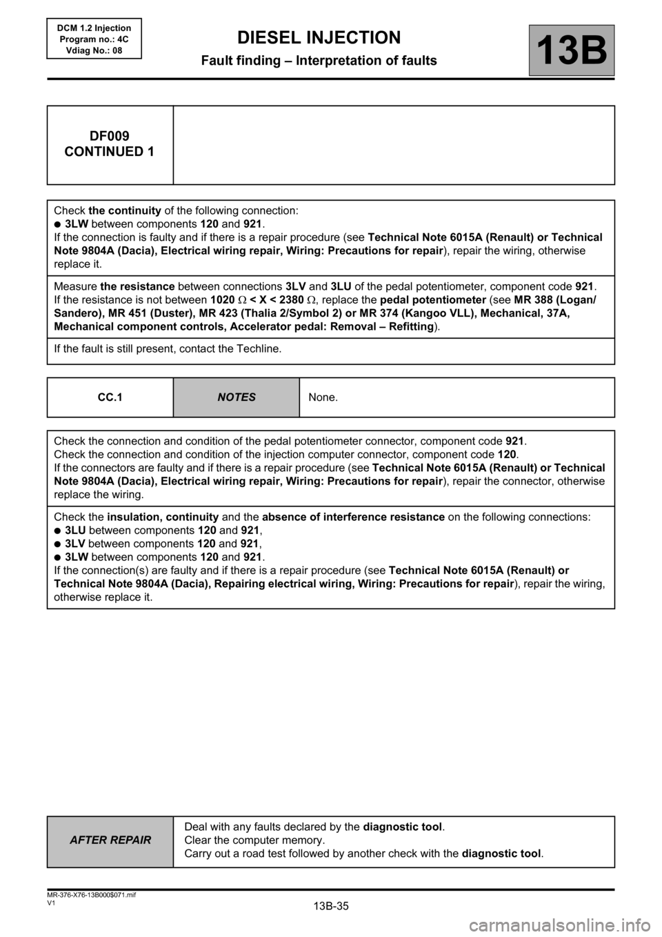
DF009
CONTINUED 1
Check the continuity of the following connection:
●3LW between components 120 and 921.
If the connection is faulty and if there is a repair procedure (see Technical Note 6015A (Renault) or Technical
Note 9804A (Dacia), Electrical wiring repair, Wiring: Precautions for repair), repair the wiring, otherwise
replace it.
Measure the resistance between connections 3LV and 3LU of the pedal potentiometer, component code 921.
If the resistance is not between 1020 < X < 2380 , replace the pedal potentiometer (see MR 388 (Logan/
Sandero), MR 451 (Duster), MR 423 (Thalia 2/Symbol 2) or MR 374 (Kangoo VLL), Mechanical, 37A,
Mechanical component controls, Accelerator pedal: Removal – Refitting).
If the fault is still present, contact the Techline.
CC.1
NOTESNone.
Check the connection and condition of the pedal potentiometer connector, component code 921.
Check the connection and condition of the injection computer connector, component code 120.
If the connectors are faulty and if there is a repair procedure (see Technical Note 6015A (Renault) or Technical
Note 9804A (Dacia), Electrical wiring repair, Wiring: Precautions for repair), repair the connector, otherwise
replace the wiring.
Check the insulation, continuity and the absence of interference resistance on the following connections:
●3LU between components 120 and 921,
●3LV between components 120 and 921,
●3LW between components 120 and 921.
If the connection(s) are faulty and if there is a repair procedure (see Technical Note 6015A (Renault) or
Technical Note 9804A (Dacia), Repairing electrical wiring, Wiring: Precautions for repair), repair the wiring,
otherwise replace it.
Page 36 of 204
13B-36
AFTER REPAIRDeal with any faults declared by the diagnostic tool.
Clear the computer memory.
Carry out a road test followed by another check with the diagnostic tool.
V1 MR-376-X76-13B000$071.mif
DIESEL INJECTION
Fault finding – Interpretation of faults13B
DCM 1.2 Injection
Program no.: 4C
Vdiag No.: 08
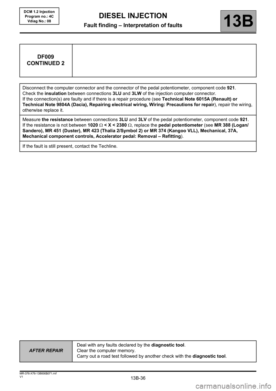
DF009
CONTINUED 2
Disconnect the computer connector and the connector of the pedal potentiometer, component code 921.
Check the insulation between connections 3LU and 3LW of the injection computer connector.
If the connection(s) are faulty and if there is a repair procedure (see Technical Note 6015A (Renault) or
Technical Note 9804A (Dacia), Repairing electrical wiring, Wiring: Precautions for repair), repair the wiring,
otherwise replace it.
Measure the resistance between connections 3LU and 3LV of the pedal potentiometer, component code 921.
If the resistance is not between 1020 < X < 2380 , replace the pedal potentiometer (see MR 388 (Logan/
Sandero), MR 451 (Duster), MR 423 (Thalia 2/Symbol 2) or MR 374 (Kangoo VLL), Mechanical, 37A,
Mechanical component controls, Accelerator pedal: Removal – Refitting).
If the fault is still present, contact the Techline.
Page 122 of 204
13B-122V1 MR-376-X76-13B000$080.mif
DIESEL INJECTION
Fault finding – Conformity check13B
DCM 1.2 Injection
Program no.: 4C
Vdiag No.: 08
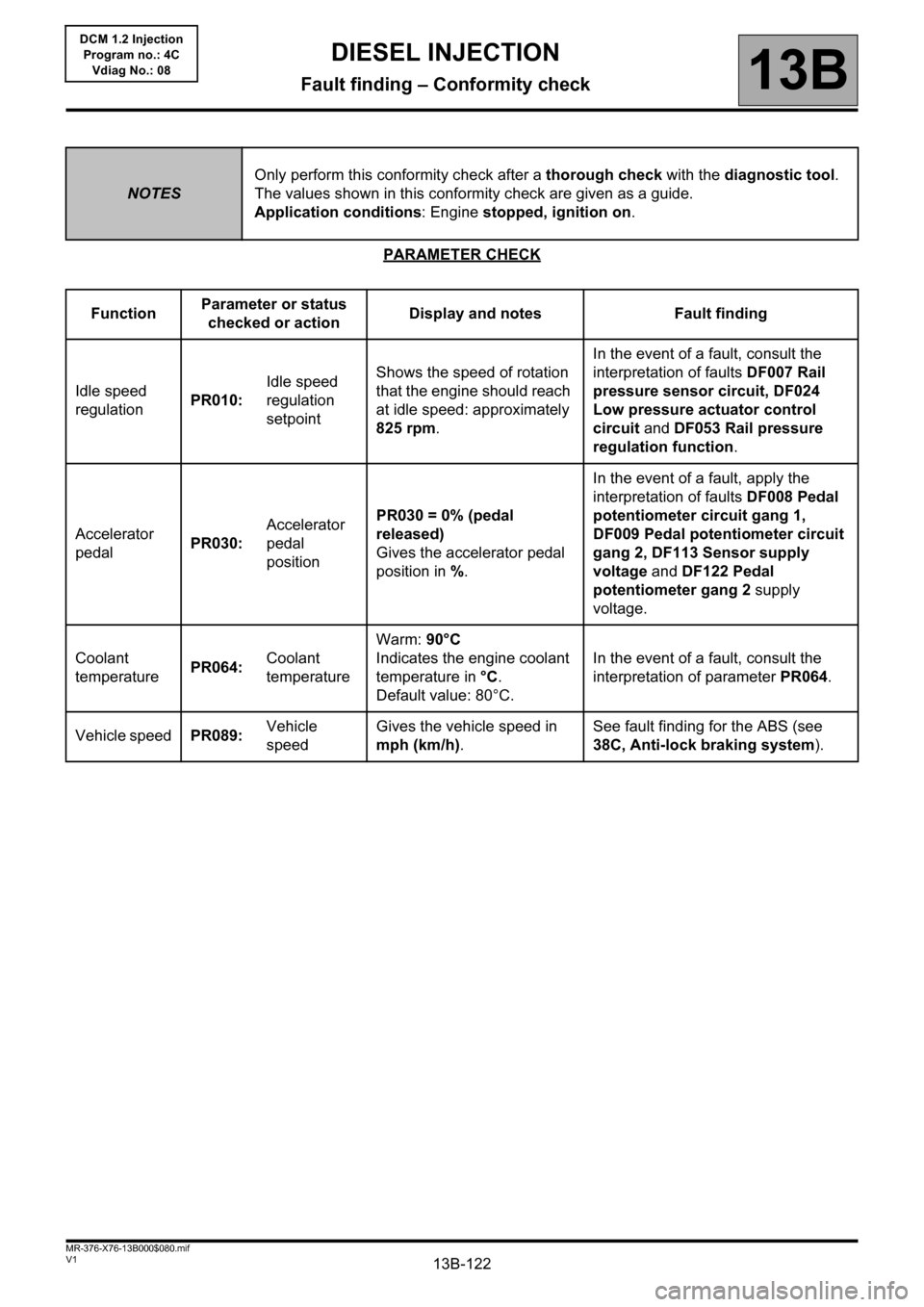
PARAMETER CHECK
NOTESOnly perform this conformity check after a thorough check with the diagnostic tool.
The values shown in this conformity check are given as a guide.
Application conditions: Engine stopped, ignition on.
FunctionParameter or status
checked or actionDisplay and notes Fault finding
Idle speed
regulationPR010:Idle speed
regulation
setpointShows the speed of rotation
that the engine should reach
at idle speed: approximately
825 rpm.In the event of a fault, consult the
interpretation of faults DF007 Rail
pressure sensor circuit, DF024
Low pressure actuator control
circuit and DF053 Rail pressure
regulation function.
Accelerator
pedalPR030:Accelerator
pedal
positionPR030 = 0% (pedal
released)
Gives the accelerator pedal
position in %.In the event of a fault, apply the
interpretation of faults DF008 Pedal
potentiometer circuit gang 1,
DF009 Pedal potentiometer circuit
gang 2, DF113 Sensor supply
voltage and DF122 Pedal
potentiometer gang 2 supply
voltage.
Coolant
temperaturePR064:Coolant
temperatureWarm: 90°C
Indicates the engine coolant
temperature in °C.
Default value: 80°C.In the event of a fault, consult the
interpretation of parameter PR064.
Vehicle speedPR089:Vehicle
speedGives the vehicle speed in
mph (km/h).See fault finding for the ABS (see
38C, Anti-lock braking system).
Page 130 of 204

13B-130V1 MR-376-X76-13B000$080.mif
DIESEL INJECTION
Fault finding – Conformity check13B
DCM 1.2 Injection
Program no.: 4C
Vdiag No.: 08
PARAMETER CHECK
NOTESOnly perform this conformity check after a complete check using the diagnostic tool.
The values shown in this conformity check are given as a guide.
Application conditions: Engine idling, warm engine, coolant temperature > 80°C.
FunctionParameter or status
checked or actionDisplay and notes Fault finding
Idle speed
regulationPR010:Idle speed
regulation
setpointShows the speed of rotation
that the engine should reach
at idle speed: approximately
825 rpm.In the event of a fault, consult the
interpretation of faults DF007 Rail
pressure sensor circuit, DF024
Low pressure actuator control
circuit and DF053 Rail pressure
regulation function.
Accelerator
pedalPR030:Accelerator
pedal
positionPR030 = 0 %
Gives the accelerator pedal
position in %.In the event of a fault, apply the
interpretation of faults DF008 Pedal
potentiometer circuit gang 1,
DF009 Pedal potentiometer circuit
gang 2, DF113 Sensor supply
voltage and DF122 Pedal
potentiometer gang 2 supply
voltage.
Coolant
temperaturePR064:Coolant
temperatureWarm: 90°C
Indicates the engine coolant
temperature in °C.
Default value: 80°C.In the event of a fault, consult the
interpretation of parameter PR064.
Vehicle speedPR089:Vehicle
speedGives the vehicle speed in
mph (km/h). This parameter
is sent by the ABS computer
or the vehicle speed
computer. Refer to fault finding for the ABS
system or the vehicle speed
computer.
Page 141 of 204
13B-141V1 MR-376-X76-13B000$110.mif
13B
DCM 1.2 Injection
Program no.: 4C
Vdiag No.: 08
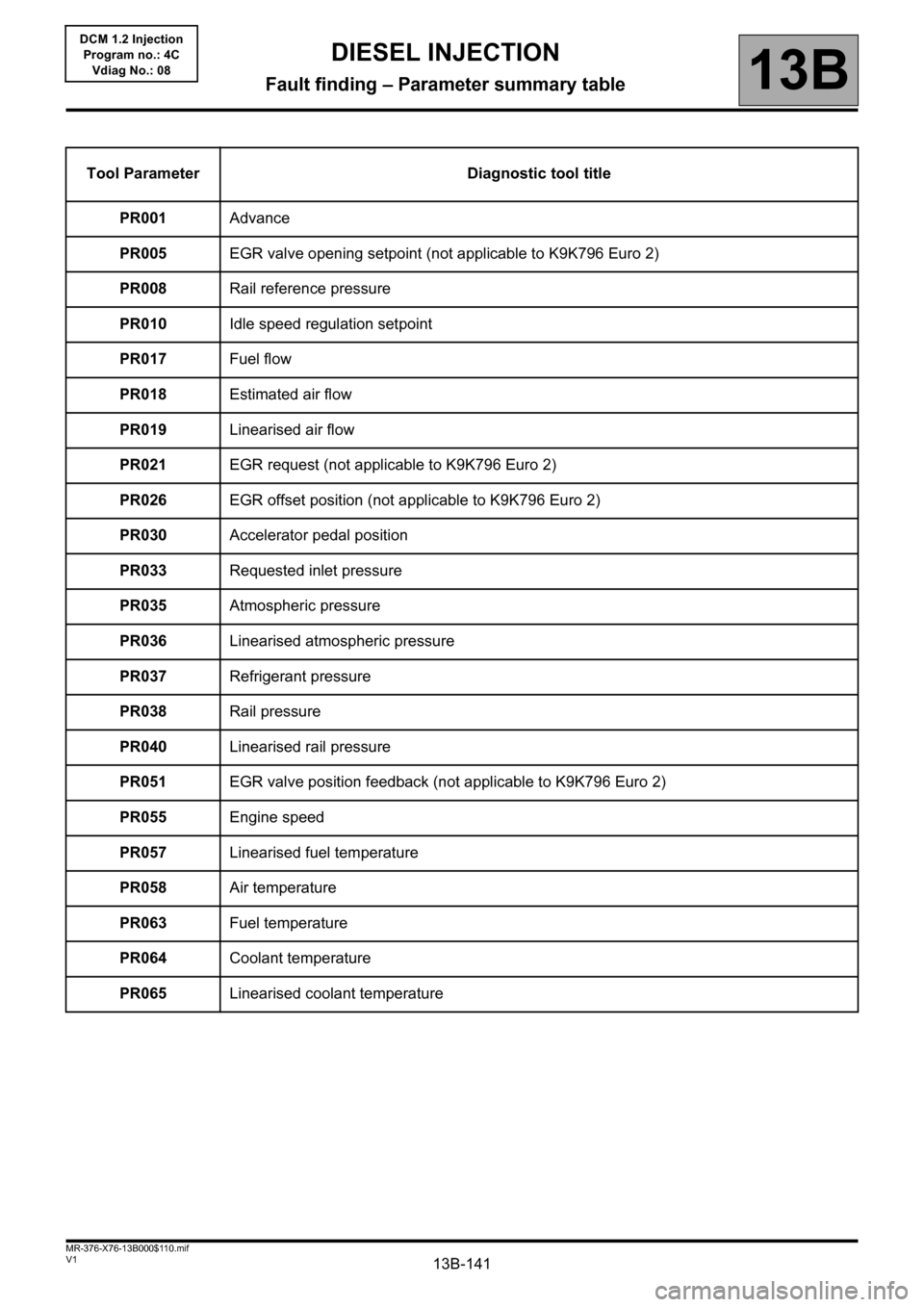
Tool Parameter Diagnostic tool title
PR001Advance
PR005EGR valve opening setpoint (not applicable to K9K796 Euro 2)
PR008Rail reference pressure
PR010Idle speed regulation setpoint
PR017Fuel flow
PR018Estimated air flow
PR019Linearised air flow
PR021EGR request (not applicable to K9K796 Euro 2)
PR026EGR offset position (not applicable to K9K796 Euro 2)
PR030Accelerator pedal position
PR033Requested inlet pressure
PR035Atmospheric pressure
PR036Linearised atmospheric pressure
PR037Refrigerant pressure
PR038Rail pressure
PR040Linearised rail pressure
PR051EGR valve position feedback (not applicable to K9K796 Euro 2)
PR055Engine speed
PR057Linearised fuel temperature
PR058Air temperature
PR063Fuel temperature
PR064Coolant temperature
PR065Linearised coolant temperature
DIESEL INJECTION
Fault finding – Parameter summary table
Page 149 of 204

13B-149V1 MR-376-X76-13B000$140.mif
DIESEL INJECTION
Fault finding – Customer complaints13B
DCM 1.2 Injection
Program no.: 4C
Vdiag No.: 08
Behaviour while driving:
Erratic acceleration/deceleration and engine racing ALP7
Acceleration gapALP8
Engine cut-out (stalling)ALP9
Engine buckingALP10
Loss of powerALP11
Too much powerALP 12
Excessive consumptionALP 13
Overspeed when releasing accelerator or changing gearALP 14
Engine dies on pulling awayALP 15
Noise, odours, or smoke:
Engine rattling, noisy engine, turbocharger noise ALP 16
Blue, white or black smoke ALP 17
Smoke (blue, white or black) on accelerationALP 18
Page 177 of 204
13B-177
AFTER REPAIRCarry out a road test followed by a check with the diagnostic tool.
V1 MR-376-X76-13B000$150.mif
DIESEL INJECTION
Fault finding – Fault Finding Chart13B
DCM 1.2 Injection
Program no.: 4C
Vdiag No.: 08
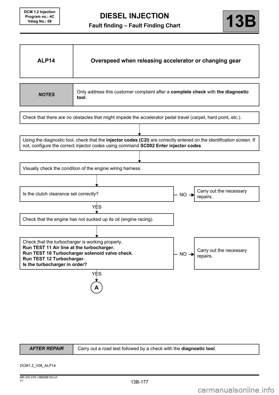
ALP14 Overspeed when releasing accelerator or changing gear
NOTESOnly address this customer complaint after a complete check with the diagnostic
tool.
Check that there are no obstacles that might impede the accelerator pedal travel (carpet, hard point, etc.).
Using the diagnostic tool, check that the injector codes (C2I) are correctly entered on the identification screen. If
not, configure the correct injector codes using command SC002 Enter injector codes
Visually check the condition of the engine wiring harness.
Is the clutch clearance set correctly?Carry out the necessary
repairs.
Check that the engine has not sucked up its oil (engine racing).
Check that the turbocharger is working properly.
Run TEST 11 Air line at the turbocharger.
Run TEST 10 Turbocharger solenoid valve check.
Run TEST 12 Turbocharger.
Is the turbocharger in order?Carry out the necessary
repairs.
NO
YES
NO
A
YES
DCM1.2_V08_ALP14