brake light RENAULT KANGOO 2013 X61 / 2.G Diesel DCM 1.2 Injection Workshop Manual
[x] Cancel search | Manufacturer: RENAULT, Model Year: 2013, Model line: KANGOO, Model: RENAULT KANGOO 2013 X61 / 2.GPages: 204, PDF Size: 0.99 MB
Page 22 of 204
13B-22V1 MR-376-X76-13B000$060.mif
13B
DCM 1.2 Injection
Program no.: 4C
Vdiag No.: 08
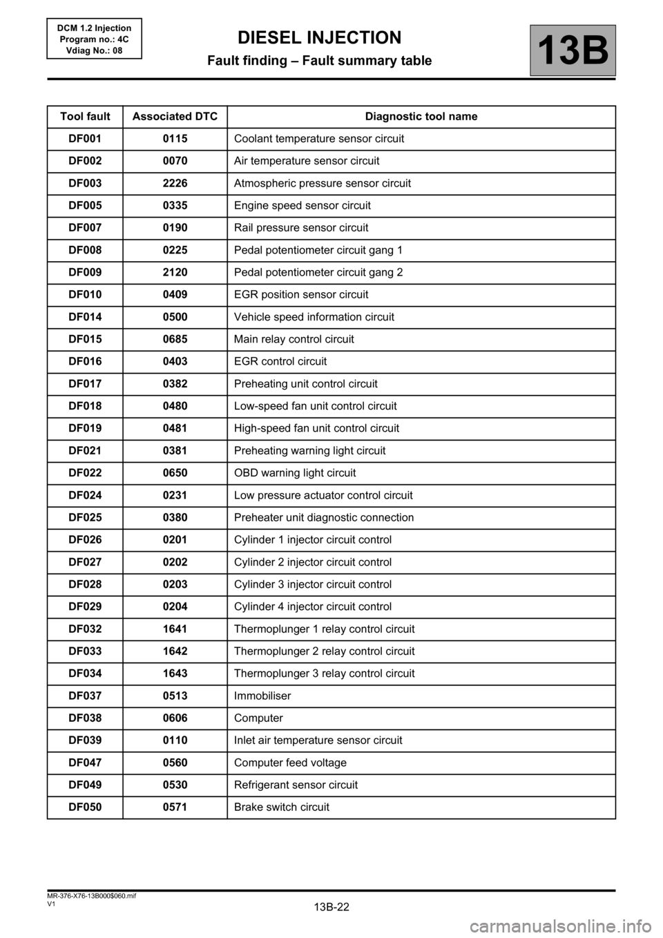
Tool fault Associated DTC Diagnostic tool name
DF001 0115Coolant temperature sensor circuit
DF002 0070Air temperature sensor circuit
DF003 2226Atmospheric pressure sensor circuit
DF005 0335Engine speed sensor circuit
DF007 0190Rail pressure sensor circuit
DF008 0225Pedal potentiometer circuit gang 1
DF009 2120Pedal potentiometer circuit gang 2
DF010 0409EGR position sensor circuit
DF014 0500Vehicle speed information circuit
DF015 0685Main relay control circuit
DF016 0403EGR control circuit
DF017 0382Preheating unit control circuit
DF018 0480Low-speed fan unit control circuit
DF019 0481High-speed fan unit control circuit
DF021 0381Preheating warning light circuit
DF022 0650OBD warning light circuit
DF024 0231Low pressure actuator control circuit
DF025 0380Preheater unit diagnostic connection
DF026 0201Cylinder 1 injector circuit control
DF027 0202Cylinder 2 injector circuit control
DF028 0203Cylinder 3 injector circuit control
DF029 0204Cylinder 4 injector circuit control
DF032 1641Thermoplunger 1 relay control circuit
DF033 1642Thermoplunger 2 relay control circuit
DF034 1643Thermoplunger 3 relay control circuit
DF037 0513Immobiliser
DF038 0606Computer
DF039 0110Inlet air temperature sensor circuit
DF047 0560Computer feed voltage
DF049 0530Refrigerant sensor circuit
DF050 0571Brake switch circuit
DIESEL INJECTION
Fault finding – Fault summary table
Page 24 of 204
13B-24V1 MR-376-X76-13B000$060.mif
DIESEL INJECTION
Fault finding – Fault summary table13B
DCM 1.2 Injection
Program no.: 4C
Vdiag No.: 08
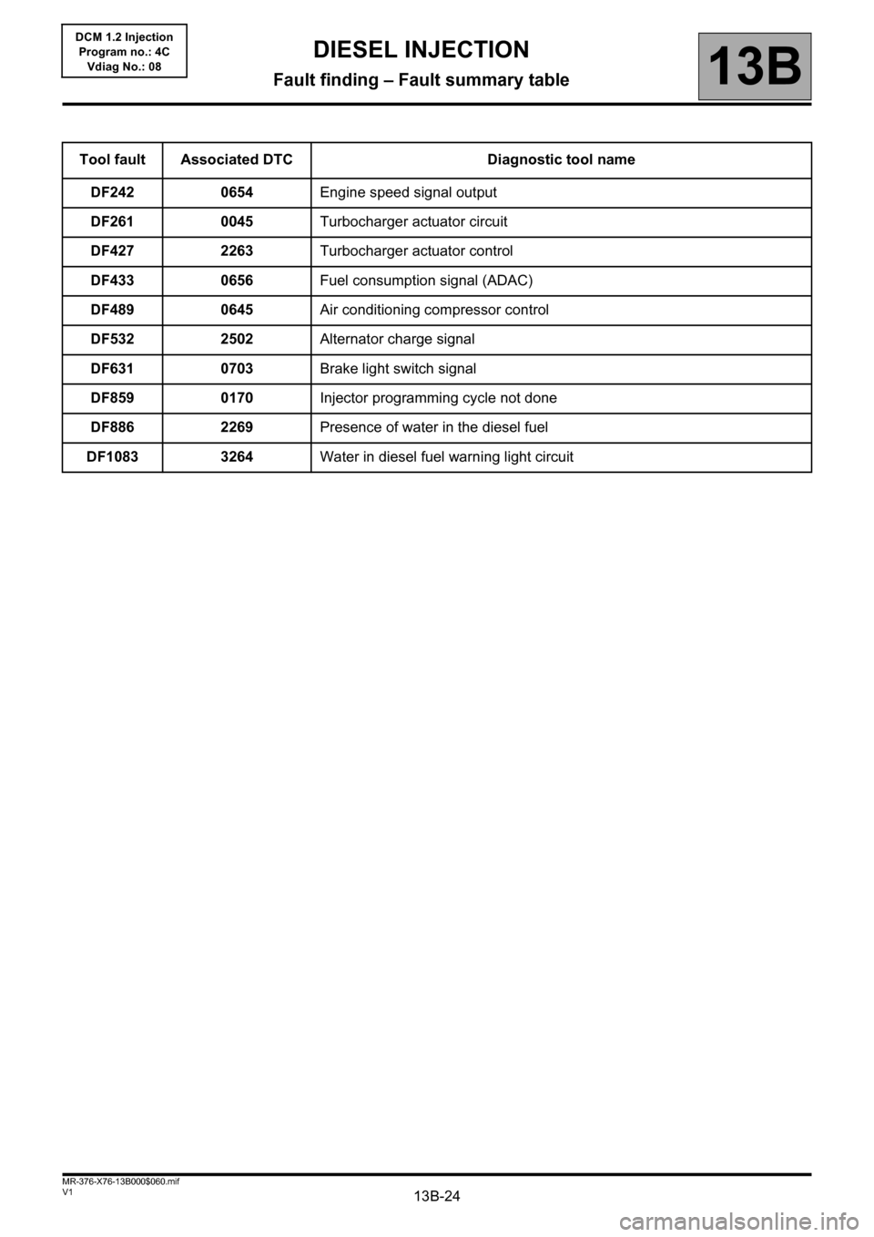
Tool fault Associated DTC Diagnostic tool name
DF242 0654Engine speed signal output
DF261 0045Turbocharger actuator circuit
DF427 2263Turbocharger actuator control
DF433 0656Fuel consumption signal (ADAC)
DF489 0645Air conditioning compressor control
DF532 2502Alternator charge signal
DF631 0703Brake light switch signal
DF859 0170Injector programming cycle not done
DF886 2269Presence of water in the diesel fuel
DF1083 3264Water in diesel fuel warning light circuit
Page 31 of 204
13B-31
AFTER REPAIRDeal with any faults declared by the diagnostic tool.
Clear the computer memory.
Carry out a road test followed by another check with the diagnostic tool.
V1 MR-376-X76-13B000$071.mif
DIESEL INJECTION
Fault finding – Interpretation of faults13B
DCM 1.2 Injection
Program no.: 4C
Vdiag No.: 08
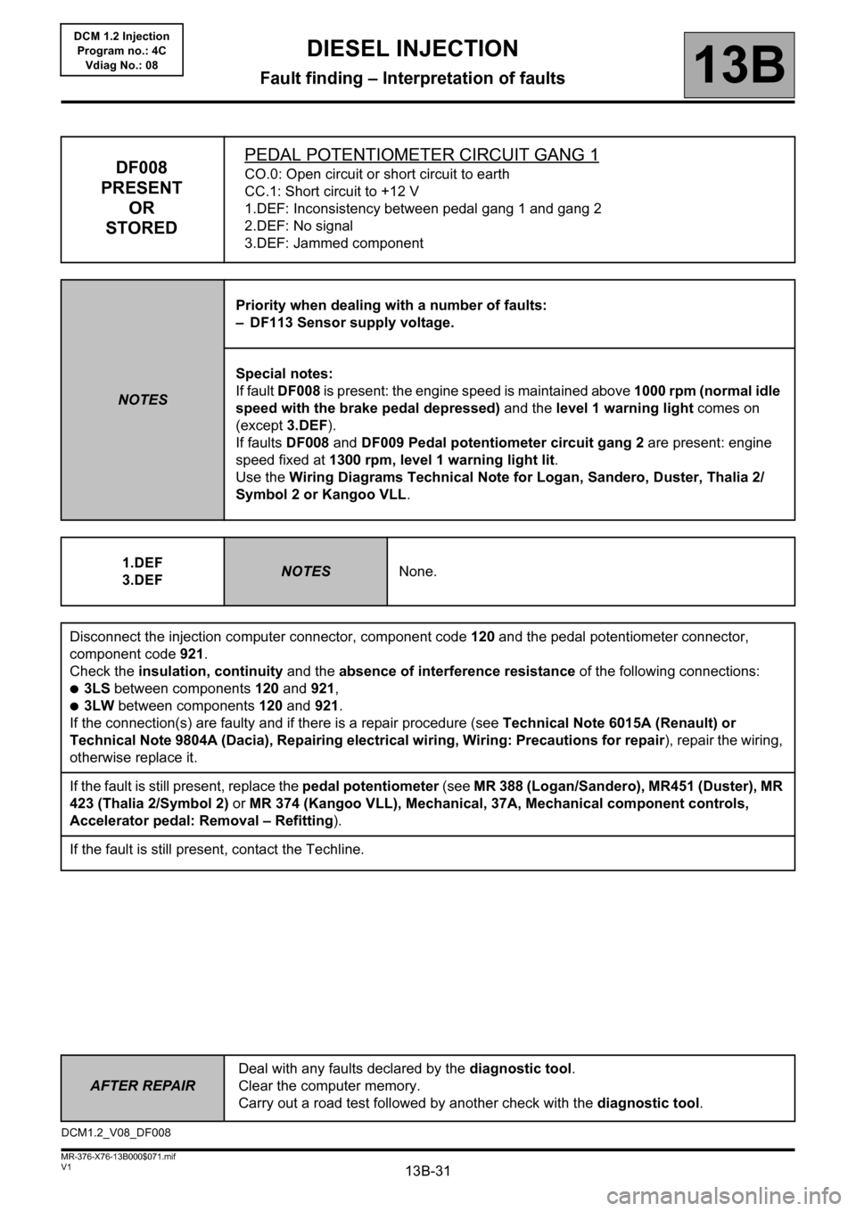
DF008
PRESENT
OR
STOREDPEDAL POTENTIOMETER CIRCUIT GANG 1CO.0: Open circuit or short circuit to earth
CC.1: Short circuit to +12 V
1.DEF: Inconsistency between pedal gang 1 and gang 2
2.DEF: No signal
3.DEF: Jammed component
NOTESPriority when dealing with a number of faults:
– DF113 Sensor supply voltage.
Special notes:
If fault DF008 is present: the engine speed is maintained above 1000 rpm (normal idle
speed with the brake pedal depressed) and the level 1 warning light comes on
(except 3.DEF).
If faults DF008 and DF009 Pedal potentiometer circuit gang 2 are present: engine
speed fixed at 1300 rpm, level 1 warning light lit.
Use the Wiring Diagrams Technical Note for Logan, Sandero, Duster, Thalia 2/
Symbol 2 or Kangoo VLL.
1.DEF
3.DEF
NOTESNone.
Disconnect the injection computer connector, component code 120 and the pedal potentiometer connector,
component code 921.
Check the insulation, continuity and the absence of interference resistance of the following connections:
●3LS between components 120 and 921,
●3LW between components 120 and 921.
If the connection(s) are faulty and if there is a repair procedure (see Technical Note 6015A (Renault) or
Technical Note 9804A (Dacia), Repairing electrical wiring, Wiring: Precautions for repair), repair the wiring,
otherwise replace it.
If the fault is still present, replace the pedal potentiometer (see MR 388 (Logan/Sandero), MR451 (Duster), MR
423 (Thalia 2/Symbol 2) or MR 374 (Kangoo VLL), Mechanical, 37A, Mechanical component controls,
Accelerator pedal: Removal – Refitting).
If the fault is still present, contact the Techline.
DCM1.2_V08_DF008
Page 73 of 204
13B-73
AFTER
REPAIRDeal with any faults declared by the diagnostic tool.
Clear the computer memory.
Carry out a road test followed by another check with the diagnostic tool.
V1 MR-376-X76-13B000$072.mif
DIESEL INJECTION
Fault finding – Interpretation of faults13B
DCM 1.2 Injection
Program no.: 4C
Vdiag No.: 08
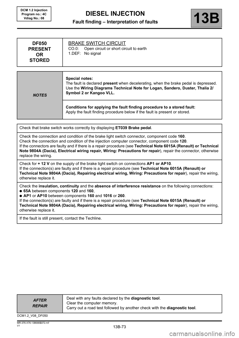
DF050
PRESENT
OR
STOREDBRAKE SWITCH CIRCUIT
CO.0: Open circuit or short circuit to earth
1.DEF: No signal
NOTESSpecial notes:
The fault is declared present when decelerating, when the brake pedal is depressed.
Use the Wiring Diagrams Technical Note for Logan, Sandero, Duster, Thalia 2/
Symbol 2 or Kangoo VLL.
Conditions for applying the fault finding procedure to a stored fault:
Apply the fault finding procedure below if the fault is present or stored.
Check that brake switch works correctly by displaying ET039 Brake pedal.
Check the connection and condition of the brake light switch connector, component code160.
Check the connection and condition of the injection computer connector, component code 120.
If the connectors are faulty and if there is a repair procedure (see Technical Note 6015A (Renault) or Technical
Note 9804A (Dacia), Electrical wiring repair, Wiring: Precautions for repair), repair the connector, otherwise
replace the wiring.
Check for + 12 V on the supply of the brake light switch on connections AP1 or AP10.
If the connection(s) are faulty and if there is a repair procedure (see Technical Note 6015A (Renault) or
Technical Note 9804A (Dacia), Repairing electrical wiring, Wiring: Precautions for repair), repair the wiring,
otherwise replace it.
Check the insulation, continuity and the absence of interference resistance on the following connections:
●65A between components 120 and 160,
●AP1 or AP10 between components 160 and 1016 or 260.
If the connection(s) are faulty and if there is a repair procedure (see Technical Note 6015A (Renault) or
Technical Note 9804A (Dacia), Repairing electrical wiring, Wiring: Precautions for repair), repair the wiring,
otherwise replace it.
If the fault is still present, contact the Techline.
DCM1.2_V08_DF050
Page 114 of 204
13B-114
AFTER
REPAIRDeal with any faults declared by the diagnostic tool.
Clear the computer memory.
Carry out a road test followed by another check with the diagnostic tool.
V1 MR-376-X76-13B000$072.mif
DIESEL INJECTION
Fault finding – Interpretation of faults13B
DCM 1.2 Injection
Program no.: 4C
Vdiag No.: 08
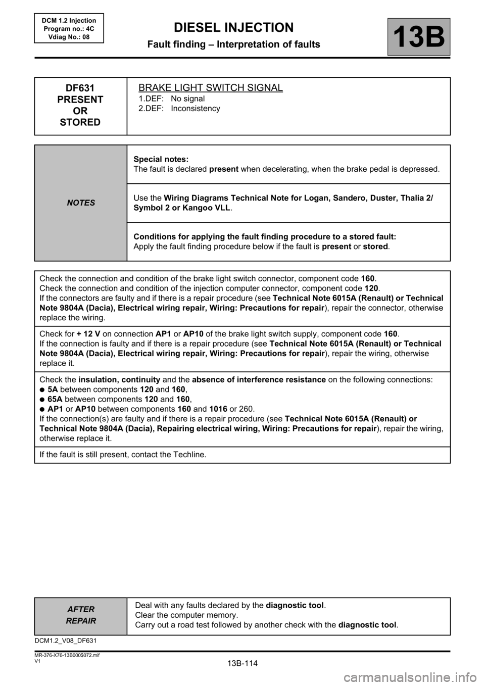
DF631
PRESENT
OR
STOREDBRAKE LIGHT SWITCH SIGNAL
1.DEF: No signal
2.DEF: Inconsistency
NOTESSpecial notes:
The fault is declared present when decelerating, when the brake pedal is depressed.
Use the Wiring Diagrams Technical Note for Logan, Sandero, Duster, Thalia 2/
Symbol 2 or Kangoo VLL.
Conditions for applying the fault finding procedure to a stored fault:
Apply the fault finding procedure below if the fault is present or stored.
Check the connection and condition of the brake light switch connector, component code160.
Check the connection and condition of the injection computer connector, component code 120.
If the connectors are faulty and if there is a repair procedure (see Technical Note 6015A (Renault) or Technical
Note 9804A (Dacia), Electrical wiring repair, Wiring: Precautions for repair), repair the connector, otherwise
replace the wiring.
Check for + 12 V on connection AP1 or AP10 of the brake light switch supply, component code 160.
If the connection is faulty and if there is a repair procedure (see Technical Note 6015A (Renault) or Technical
Note 9804A (Dacia), Electrical wiring repair, Wiring: Precautions for repair), repair the wiring, otherwise
replace it.
Check the insulation, continuity and the absence of interference resistance on the following connections:
●5A between components 120 and 160,
●65A between components 120 and 160,
●AP1 or AP10 between components 160 and 1016 or 260.
If the connection(s) are faulty and if there is a repair procedure (see Technical Note 6015A (Renault) or
Technical Note 9804A (Dacia), Repairing electrical wiring, Wiring: Precautions for repair), repair the wiring,
otherwise replace it.
If the fault is still present, contact the Techline.
DCM1.2_V08_DF631
Page 136 of 204
13B-136
AFTER REPAIRDeal with any faults. Clear the faults from the computer memory.
Switch off the ignition and carry out a road test followed by a test with the diagnostic
tool.
V1 MR-376-X76-13B000$100.mif
13B
DCM 1.2 Injection
Program no.: 4C
Vdiag No.: 08
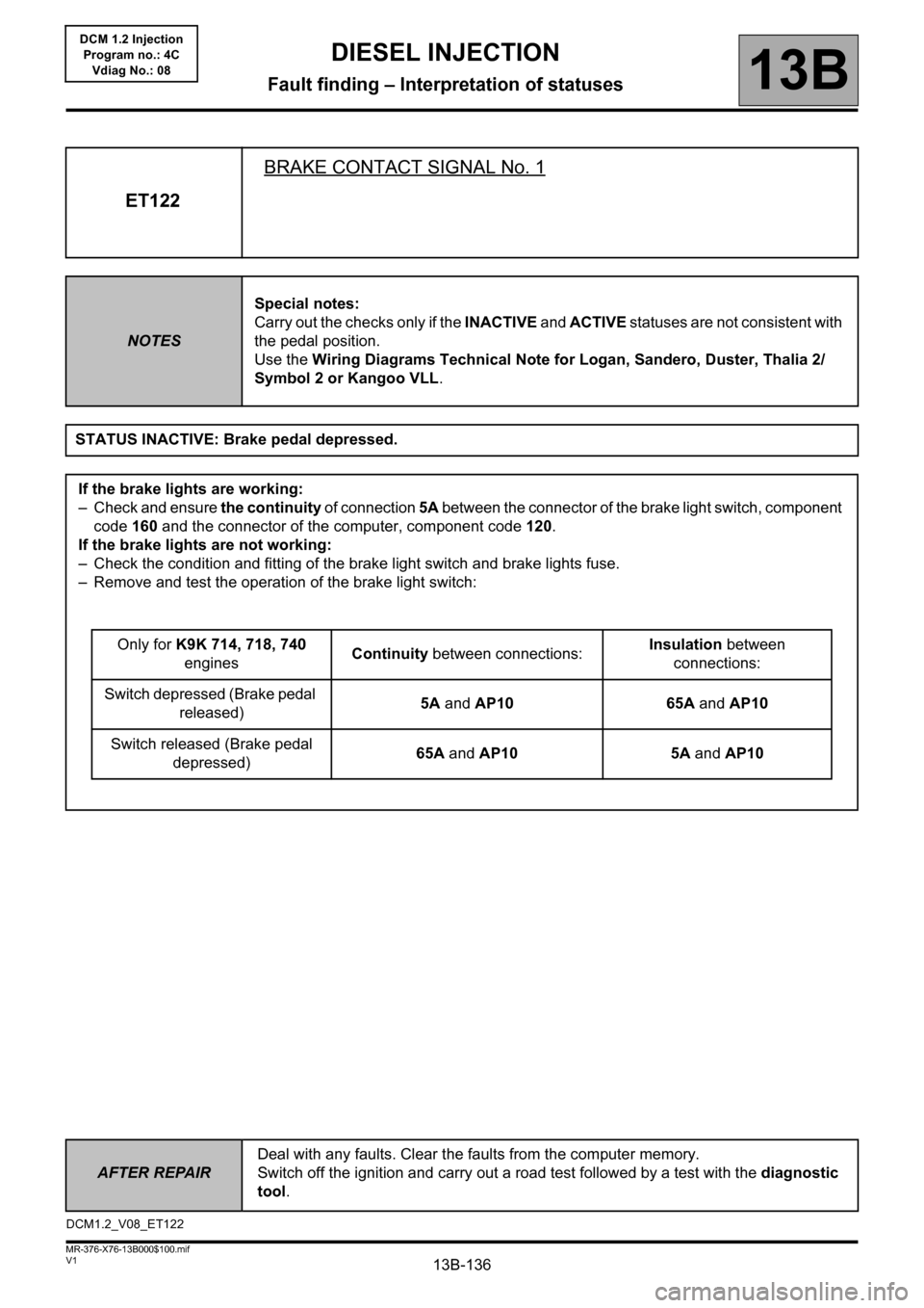
ET122BRAKE CONTACT SIGNAL No. 1
NOTESSpecial notes:
Carry out the checks only if the INACTIVE and ACTIVE statuses are not consistent with
the pedal position.
Use the Wiring Diagrams Technical Note for Logan, Sandero, Duster, Thalia 2/
Symbol 2 or Kangoo VLL.
STATUS INACTIVE: Brake pedal depressed.
If the brake lights are working:
– Check and ensure the continuity of connection 5A between the connector of the brake light switch, component
code 160 and the connector of the computer, component code 120.
If the brake lights are not working:
– Check the condition and fitting of the brake light switch and brake lights fuse.
– Remove and test the operation of the brake light switch:
Only for K9K 714, 718, 740
enginesContinuity between connections:Insulation between
connections:
Switch depressed (Brake pedal
released)5A and AP10 65A and AP10
Switch released (Brake pedal
depressed)65A and AP10 5A and AP10
DCM1.2_V08_ET122
DIESEL INJECTION
Fault finding – Interpretation of statuses
Page 137 of 204
13B-137
AFTER REPAIRDeal with any faults. Clear the faults from the computer memory.
Switch off the ignition and carry out a road test followed by a test with the diagnostic
tool.
V1 MR-376-X76-13B000$100.mif
DIESEL INJECTION
Fault finding – Interpretation of statuses13B
DCM 1.2 Injection
Program no.: 4C
Vdiag No.: 08
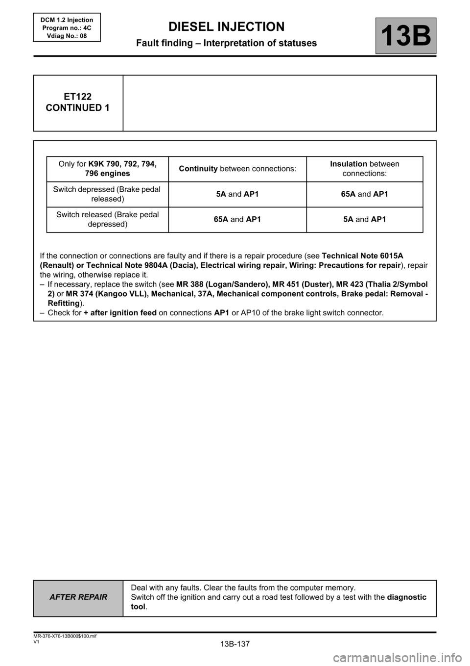
ET122
CONTINUED 1
Only for K9K 790, 792, 794,
796 enginesContinuity between connections:Insulation between
connections:
Switch depressed (Brake pedal
released)5A and AP1 65A and AP1
Switch released (Brake pedal
depressed)65A and AP1 5A and AP1
If the connection or connections are faulty and if there is a repair procedure (see Technical Note 6015A
(Renault) or Technical Note 9804A (Dacia), Electrical wiring repair, Wiring: Precautions for repair), repair
the wiring, otherwise replace it.
– If necessary, replace the switch (see MR 388 (Logan/Sandero), MR 451 (Duster), MR 423 (Thalia 2/Symbol
2) or MR 374 (Kangoo VLL), Mechanical, 37A, Mechanical component controls, Brake pedal: Removal -
Refitting).
– Check for + after ignition feed on connections AP1 or AP10 of the brake light switch connector.
Page 138 of 204
13B-138
AFTER REPAIRDeal with any faults. Clear the faults from the computer memory.
Switch off the ignition and carry out a road test followed by a test with the diagnostic
tool.
V1 MR-376-X76-13B000$100.mif
DIESEL INJECTION
Fault finding – Interpretation of statuses13B
DCM 1.2 Injection
Program no.: 4C
Vdiag No.: 08
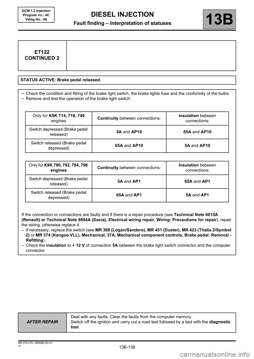
ET122
CONTINUED 2
STATUS ACTIVE: Brake pedal released.
– Check the condition and fitting of the brake light switch, the brake lights fuse and the conformity of the bulbs.
– Remove and test the operation of the brake light switch:
Only for K9K 714, 718, 740
enginesContinuity between connections:Insulation between
connections:
Switch depressed (Brake pedal
released)5A and AP10 65A and AP10
Switch released (Brake pedal
depressed)65A and AP10 5A and AP10
Only for K9K 790, 792, 794, 796
enginesContinuity between connections:Insulation between
connections:
Switch depressed (Brake pedal
released)5A and AP1 65A and AP1
Switch released (Brake pedal
depressed)65A and AP1 5A and AP1
If the connection or connections are faulty and if there is a repair procedure (see Technical Note 6015A
(Renault) or Technical Note 9804A (Dacia), Electrical wiring repair, Wiring: Precautions for repair), repair
the wiring, otherwise replace it.
– If necessary, replace the switch (see MR 388 (Logan/Sandero), MR 451 (Duster), MR 423 (Thalia 2/Symbol
2) or MR 374 (Kangoo VLL), Mechanical, 37A, Mechanical component controls, Brake pedal: Removal -
Refitting).
– Check the insulation to + 12 V of connection 5A between the brake light switch connector and the computer
connector.