df016 RENAULT KANGOO 2013 X61 / 2.G Diesel DCM 1.2 Injection Workshop Manual
[x] Cancel search | Manufacturer: RENAULT, Model Year: 2013, Model line: KANGOO, Model: RENAULT KANGOO 2013 X61 / 2.GPages: 204, PDF Size: 0.99 MB
Page 16 of 204
13B-16V1 MR-376-X76-13B000$030.mif
DIESEL INJECTION
Fault finding – System operation13B
DCM 1.2 Injection
Program no.: 4C
Vdiag No.: 08
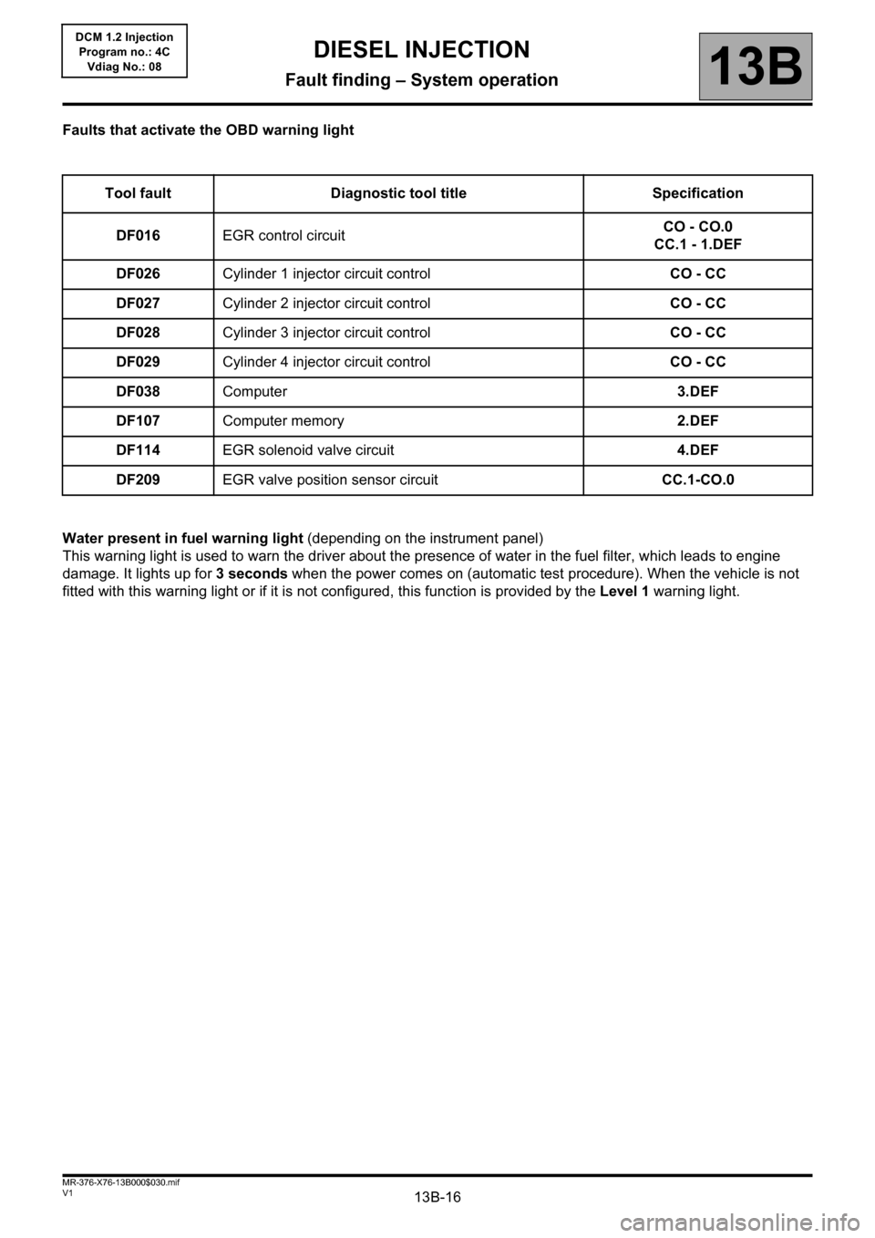
Faults that activate the OBD warning light
Water present in fuel warning light (depending on the instrument panel)
This warning light is used to warn the driver about the presence of water in the fuel filter, which leads to engine
damage. It lights up for 3 seconds when the power comes on (automatic test procedure). When the vehicle is not
fitted with this warning light or if it is not configured, this function is provided by the Level 1 warning light. Tool fault Diagnostic tool title Specification
DF016EGR control circuitCO - CO.0
CC.1 - 1.DEF
DF026Cylinder 1 injector circuit controlCO - CC
DF027Cylinder 2 injector circuit controlCO - CC
DF028Cylinder 3 injector circuit controlCO - CC
DF029Cylinder 4 injector circuit controlCO - CC
DF038Computer3.DEF
DF107Computer memory2.DEF
DF114EGR solenoid valve circuit4.DEF
DF209EGR valve position sensor circuitCC.1-CO.0
Page 22 of 204
13B-22V1 MR-376-X76-13B000$060.mif
13B
DCM 1.2 Injection
Program no.: 4C
Vdiag No.: 08
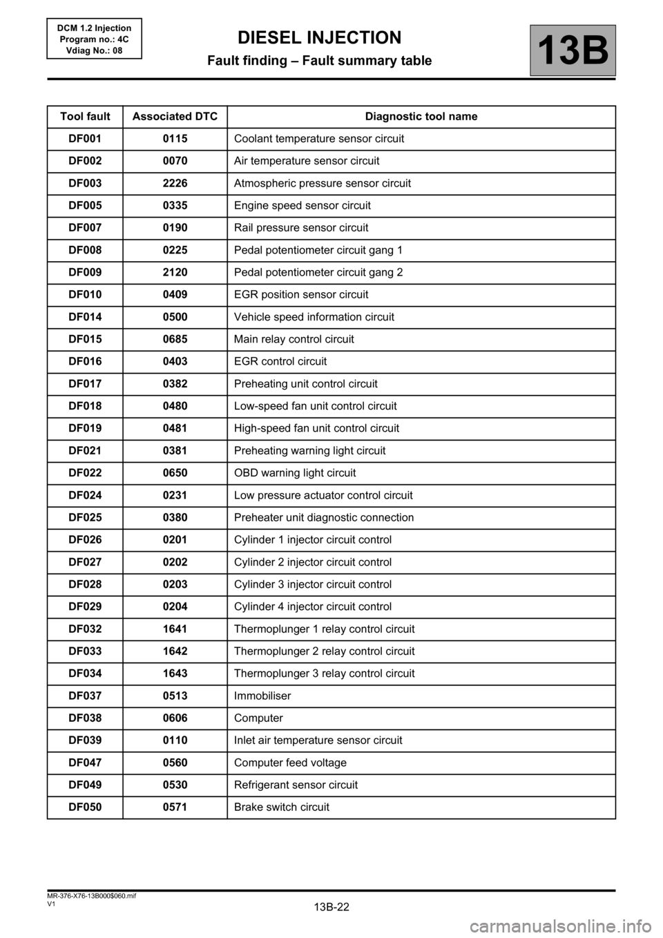
Tool fault Associated DTC Diagnostic tool name
DF001 0115Coolant temperature sensor circuit
DF002 0070Air temperature sensor circuit
DF003 2226Atmospheric pressure sensor circuit
DF005 0335Engine speed sensor circuit
DF007 0190Rail pressure sensor circuit
DF008 0225Pedal potentiometer circuit gang 1
DF009 2120Pedal potentiometer circuit gang 2
DF010 0409EGR position sensor circuit
DF014 0500Vehicle speed information circuit
DF015 0685Main relay control circuit
DF016 0403EGR control circuit
DF017 0382Preheating unit control circuit
DF018 0480Low-speed fan unit control circuit
DF019 0481High-speed fan unit control circuit
DF021 0381Preheating warning light circuit
DF022 0650OBD warning light circuit
DF024 0231Low pressure actuator control circuit
DF025 0380Preheater unit diagnostic connection
DF026 0201Cylinder 1 injector circuit control
DF027 0202Cylinder 2 injector circuit control
DF028 0203Cylinder 3 injector circuit control
DF029 0204Cylinder 4 injector circuit control
DF032 1641Thermoplunger 1 relay control circuit
DF033 1642Thermoplunger 2 relay control circuit
DF034 1643Thermoplunger 3 relay control circuit
DF037 0513Immobiliser
DF038 0606Computer
DF039 0110Inlet air temperature sensor circuit
DF047 0560Computer feed voltage
DF049 0530Refrigerant sensor circuit
DF050 0571Brake switch circuit
DIESEL INJECTION
Fault finding – Fault summary table
Page 42 of 204
13B-42
AFTER REPAIRDeal with any faults declared by the diagnostic tool.
Clear the computer memory.
Carry out a road test followed by another check with the diagnostic tool.
V1 MR-376-X76-13B000$071.mif
DIESEL INJECTION
Fault finding – Interpretation of faults13B
DCM 1.2 Injection
Program no.: 4C
Vdiag No.: 08
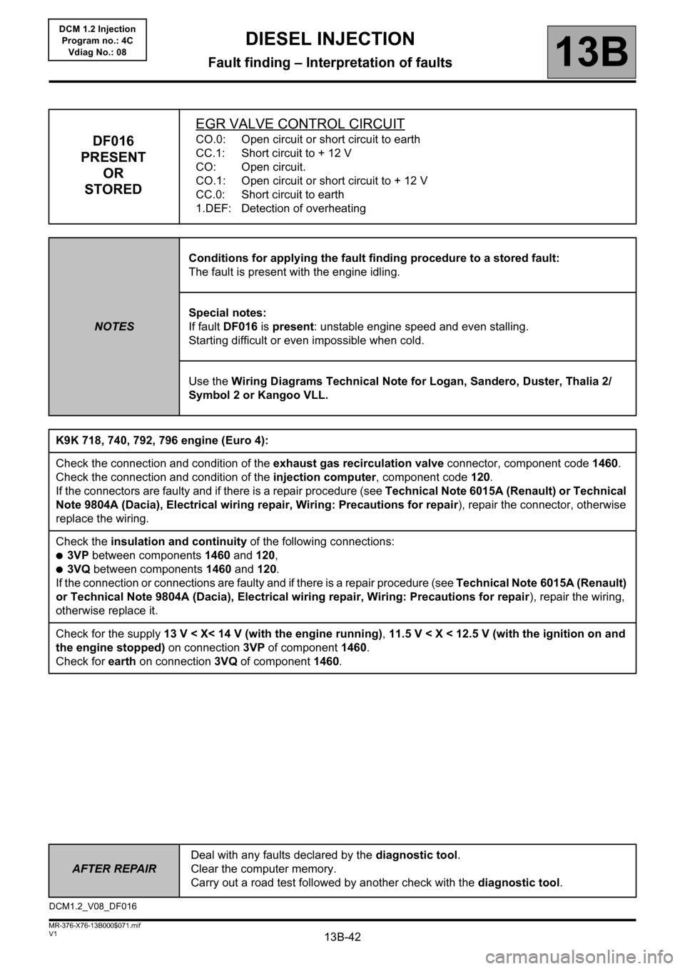
DF016
PRESENT
OR
STOREDEGR VALVE CONTROL CIRCUITCO.0: Open circuit or short circuit to earth
CC.1: Short circuit to + 12 V
CO: Open circuit.
CO.1: Open circuit or short circuit to + 12 V
CC.0: Short circuit to earth
1.DEF: Detection of overheating
NOTESConditions for applying the fault finding procedure to a stored fault:
The fault is present with the engine idling.
Special notes:
If fault DF016 is present: unstable engine speed and even stalling.
Starting difficult or even impossible when cold.
Use the Wiring Diagrams Technical Note for Logan, Sandero, Duster, Thalia 2/
Symbol 2 or Kangoo VLL.
K9K 718, 740, 792, 796 engine (Euro 4):
Check the connection and condition of the exhaust gas recirculation valve connector, component code 1460.
Check the connection and condition of the injection computer, component code 120.
If the connectors are faulty and if there is a repair procedure (see Technical Note 6015A (Renault) or Technical
Note 9804A (Dacia), Electrical wiring repair, Wiring: Precautions for repair), repair the connector, otherwise
replace the wiring.
Check the insulation and continuity of the following connections:
●3VP between components 1460 and 120,
●3VQ between components 1460 and 120.
If the connection or connections are faulty and if there is a repair procedure (see Technical Note 6015A (Renault)
or Technical Note 9804A (Dacia), Electrical wiring repair, Wiring: Precautions for repair), repair the wiring,
otherwise replace it.
Check for the supply 13 V < X< 14 V (with the engine running), 11.5 V < X < 12.5 V (with the ignition on and
the engine stopped) on connection 3VP of component 1460.
Check for earth on connection 3VQ of component 1460.
DCM1.2_V08_DF016
Page 43 of 204
13B-43
AFTER REPAIRDeal with any faults declared by the diagnostic tool.
Clear the computer memory.
Carry out a road test followed by another check with the diagnostic tool.
V1 MR-376-X76-13B000$071.mif
DIESEL INJECTION
Fault finding – Interpretation of faults13B
DCM 1.2 Injection
Program no.: 4C
Vdiag No.: 08
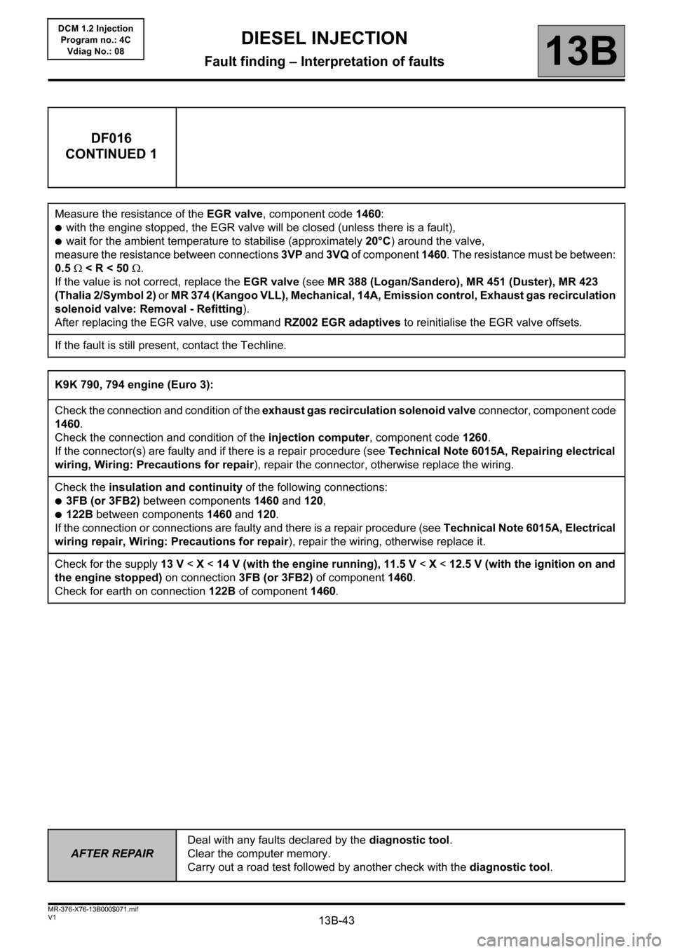
DF016
CONTINUED 1
Measure the resistance of the EGR valve, component code 1460:
●with the engine stopped, the EGR valve will be closed (unless there is a fault),
●wait for the ambient temperature to stabilise (approximately 20°C) around the valve,
measure the resistance between connections 3VP and 3VQ of component 1460. The resistance must be between:
0.5 < R < 50 .
If the value is not correct, replace the EGR valve (see MR 388 (Logan/Sandero), MR 451 (Duster), MR 423
(Thalia 2/Symbol 2) or MR 374 (Kangoo VLL), Mechanical, 14A, Emission control, Exhaust gas recirculation
solenoid valve: Removal - Refitting).
After replacing the EGR valve, use command RZ002 EGR adaptives to reinitialise the EGR valve offsets.
If the fault is still present, contact the Techline.
K9K 790, 794 engine (Euro 3):
Check the connection and condition of the exhaust gas recirculation solenoid valve connector, component code
1460.
Check the connection and condition of the injection computer, component code 1260.
If the connector(s) are faulty and if there is a repair procedure (see Technical Note 6015A, Repairing electrical
wiring, Wiring: Precautions for repair), repair the connector, otherwise replace the wiring.
Check the insulation and continuity of the following connections:
●3FB (or 3FB2) between components 1460 and 120,
●122B between components 1460 and 120.
If the connection or connections are faulty and there is a repair procedure (see Technical Note 6015A, Electrical
wiring repair, Wiring: Precautions for repair), repair the wiring, otherwise replace it.
Check for the supply 13 V < X < 14 V (with the engine running), 11.5 V < X < 12.5 V (with the ignition on and
the engine stopped) on connection 3FB (or 3FB2) of component 1460.
Check for earth on connection122B of component1460.
Page 44 of 204
13B-44
AFTER REPAIRDeal with any faults declared by the diagnostic tool.
Clear the computer memory.
Carry out a road test followed by another check with the diagnostic tool.
V1 MR-376-X76-13B000$071.mif
DIESEL INJECTION
Fault finding – Interpretation of faults13B
DCM 1.2 Injection
Program no.: 4C
Vdiag No.: 08
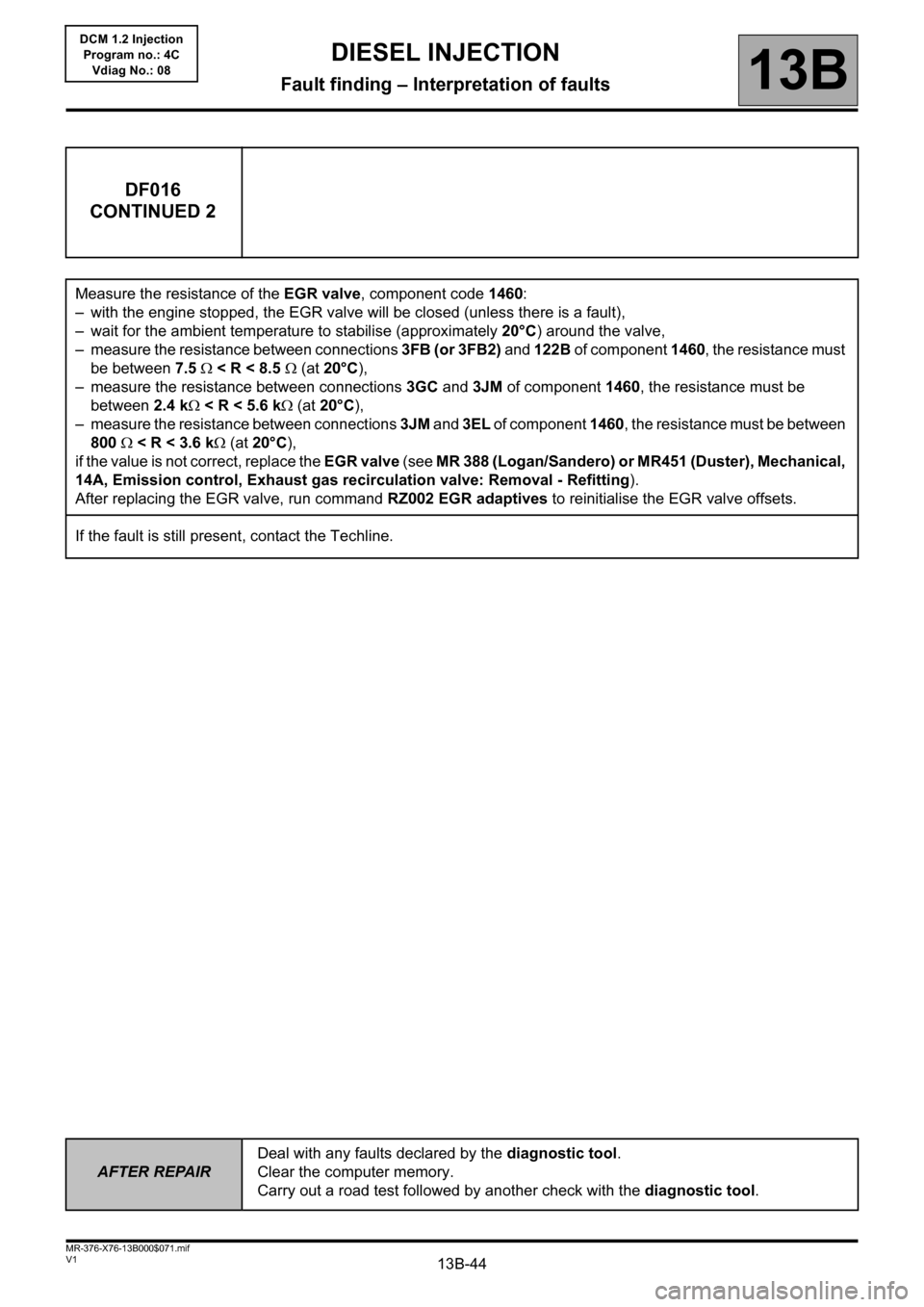
DF016
CONTINUED 2
Measure the resistance of the EGR valve, component code 1460:
– with the engine stopped, the EGR valve will be closed (unless there is a fault),
– wait for the ambient temperature to stabilise (approximately 20°C) around the valve,
– measure the resistance between connections 3FB (or 3FB2) and 122B of component 1460, the resistance must
be between 7.5 < R < 8.5 (at 20°C),
– measure the resistance between connections 3GC and 3JM of component 1460, the resistance must be
between 2.4 k < R < 5.6 k (at 20°C),
– measure the resistance between connections 3JM and 3EL of component 1460, the resistance must be between
800 < R < 3.6 k (at 20°C),
if the value is not correct, replace the EGR valve (see MR 388 (Logan/Sandero) or MR451 (Duster), Mechanical,
14A, Emission control, Exhaust gas recirculation valve: Removal - Refitting).
After replacing the EGR valve, run command RZ002 EGR adaptives to reinitialise the EGR valve offsets.
If the fault is still present, contact the Techline.
Page 125 of 204
13B-125V1 MR-376-X76-13B000$080.mif
DIESEL INJECTION
Fault finding – Conformity check13B
DCM 1.2 Injection
Program no.: 4C
Vdiag No.: 08
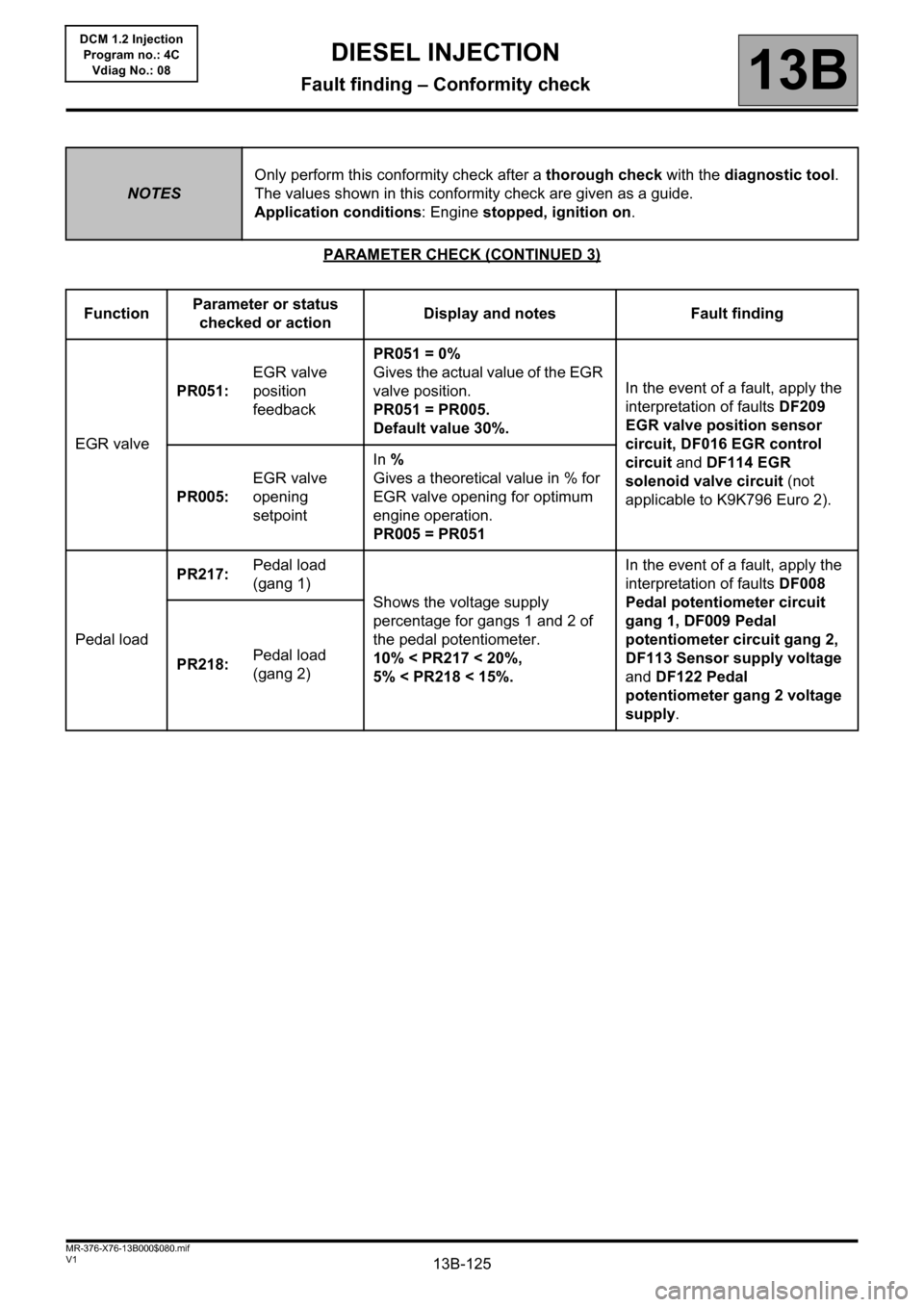
PARAMETER CHECK (CONTINUED 3)
NOTESOnly perform this conformity check after a thorough check with the diagnostic tool.
The values shown in this conformity check are given as a guide.
Application conditions: Engine stopped, ignition on.
FunctionParameter or status
checked or actionDisplay and notes Fault finding
EGR valvePR051:EGR valve
position
feedbackPR051 = 0%
Gives the actual value of the EGR
valve position.
PR051 = PR005.
Default value 30%.In the event of a fault, apply the
interpretation of faults DF209
EGR valve position sensor
circuit, DF016 EGR control
circuit and DF114 EGR
solenoid valve circuit (not
applicable to K9K796 Euro 2). PR005:EGR valve
opening
setpointIn %
Gives a theoretical value in % for
EGR valve opening for optimum
engine operation.
PR005 = PR051
Pedal loadPR217:Pedal load
(gang 1)
Shows the voltage supply
percentage for gangs 1 and 2 of
the pedal potentiometer.
10% < PR217 < 20%,
5% < PR218 < 15%.In the event of a fault, apply the
interpretation of faults DF008
Pedal potentiometer circuit
gang 1, DF009 Pedal
potentiometer circuit gang 2,
DF113 Sensor supply voltage
and DF122 Pedal
potentiometer gang 2 voltage
supply. PR218:Pedal load
(gang 2)
Page 128 of 204
13B-128V1 MR-376-X76-13B000$080.mif
DIESEL INJECTION
Fault finding – Conformity check13B
DCM 1.2 Injection
Program no.: 4C
Vdiag No.: 08
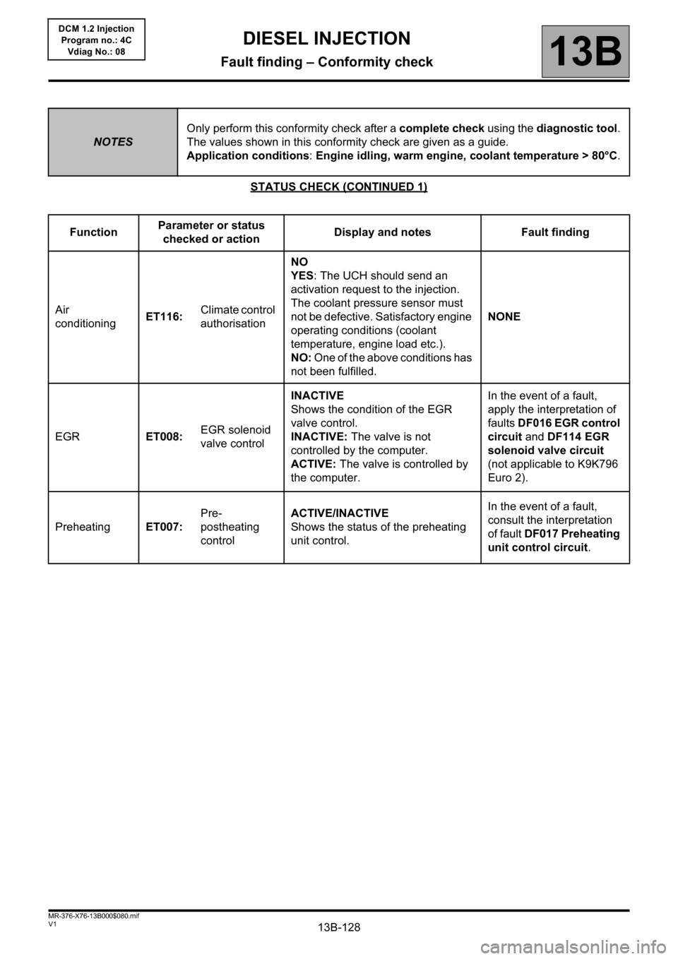
STATUS CHECK (CONTINUED 1)
NOTESOnly perform this conformity check after a complete check using the diagnostic tool.
The values shown in this conformity check are given as a guide.
Application conditions: Engine idling, warm engine, coolant temperature > 80°C.
FunctionParameter or status
checked or actionDisplay and notes Fault finding
Air
conditioningET116:Climate control
authorisationNO
YES: The UCH should send an
activation request to the injection.
The coolant pressure sensor must
not be defective. Satisfactory engine
operating conditions (coolant
temperature, engine load etc.).
NO: One of the above conditions has
not been fulfilled.NONE
EGRET008:EGR solenoid
valve controlINACTIVE
Shows the condition of the EGR
valve control.
INACTIVE: The valve is not
controlled by the computer.
ACTIVE: The valve is controlled by
the computer.In the event of a fault,
apply the interpretation of
faults DF016 EGR control
circuit and DF114 EGR
solenoid valve circuit
(not applicable to K9K796
Euro 2).
PreheatingET007:Pre-
postheating
controlACTIVE/INACTIVE
Shows the status of the preheating
unit control.In the event of a fault,
consult the interpretation
of fault DF017 Preheating
unit control circuit.
Page 133 of 204
13B-133V1 MR-376-X76-13B000$080.mif
DIESEL INJECTION
Fault finding – Conformity check13B
DCM 1.2 Injection
Program no.: 4C
Vdiag No.: 08
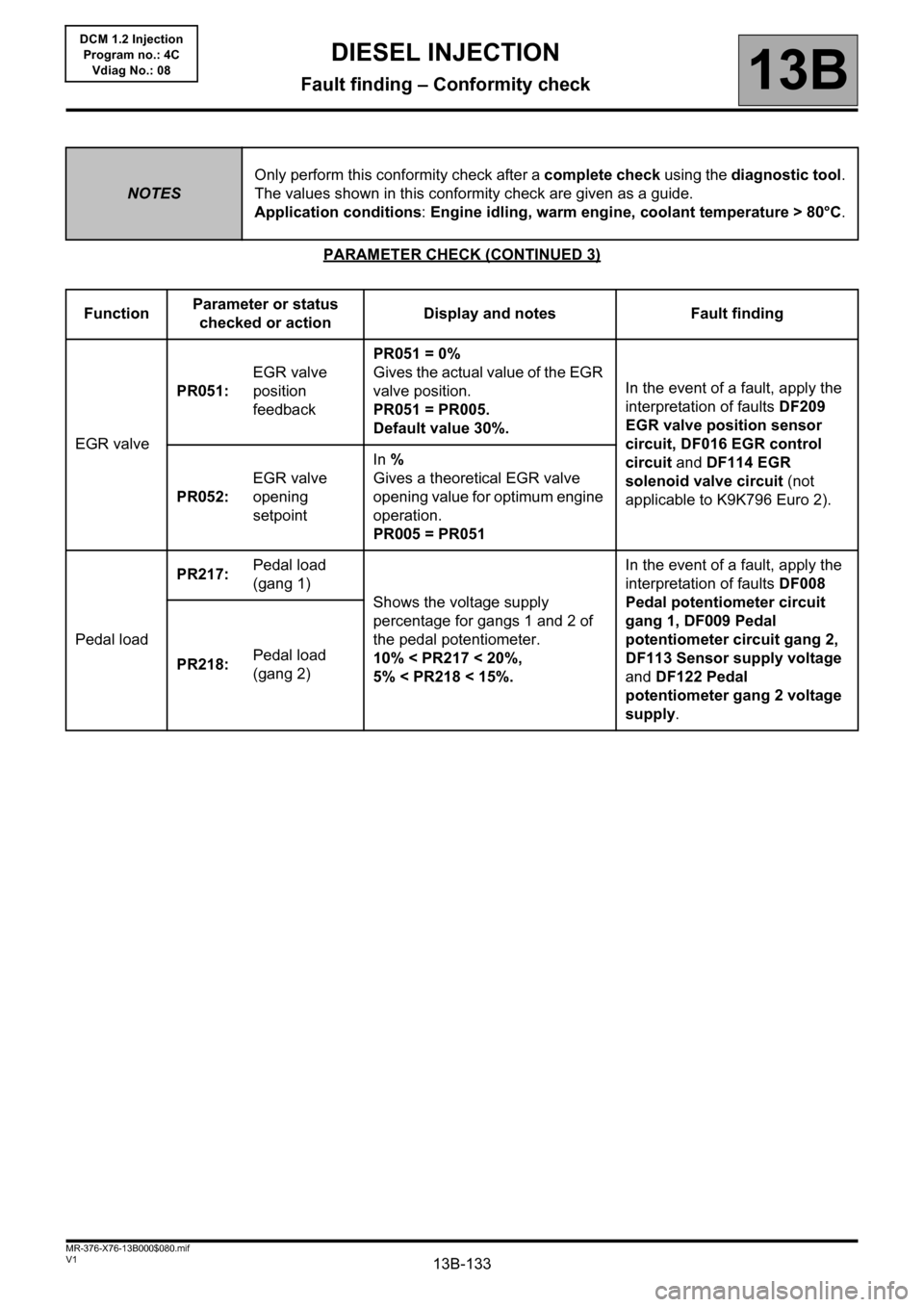
PARAMETER CHECK (CONTINUED 3)
NOTESOnly perform this conformity check after a complete check using the diagnostic tool.
The values shown in this conformity check are given as a guide.
Application conditions: Engine idling, warm engine, coolant temperature > 80°C.
FunctionParameter or status
checked or actionDisplay and notes Fault finding
EGR valvePR051:EGR valve
position
feedbackPR051 = 0%
Gives the actual value of the EGR
valve position.
PR051 = PR005.
Default value 30%.In the event of a fault, apply the
interpretation of faults DF209
EGR valve position sensor
circuit, DF016 EGR control
circuit and DF114 EGR
solenoid valve circuit (not
applicable to K9K796 Euro 2). PR052:EGR valve
opening
setpointIn %
Gives a theoretical EGR valve
opening value for optimum engine
operation.
PR005 = PR051
Pedal loadPR217:Pedal load
(gang 1)
Shows the voltage supply
percentage for gangs 1 and 2 of
the pedal potentiometer.
10% < PR217 < 20%,
5% < PR218 < 15%.In the event of a fault, apply the
interpretation of faults DF008
Pedal potentiometer circuit
gang 1, DF009 Pedal
potentiometer circuit gang 2,
DF113 Sensor supply voltage
and DF122 Pedal
potentiometer gang 2 voltage
supply. PR218:Pedal load
(gang 2)