k9k 714 RENAULT KANGOO 2013 X61 / 2.G Diesel DCM 1.2 Injection Workshop Manual
[x] Cancel search | Manufacturer: RENAULT, Model Year: 2013, Model line: KANGOO, Model: RENAULT KANGOO 2013 X61 / 2.GPages: 204, PDF Size: 0.99 MB
Page 2 of 204
13B-2V1 MR-376-X76-13B000$010.mif
13B
DCM 1.2 Injection
Program no.: 4C
Vdiag No.: 08
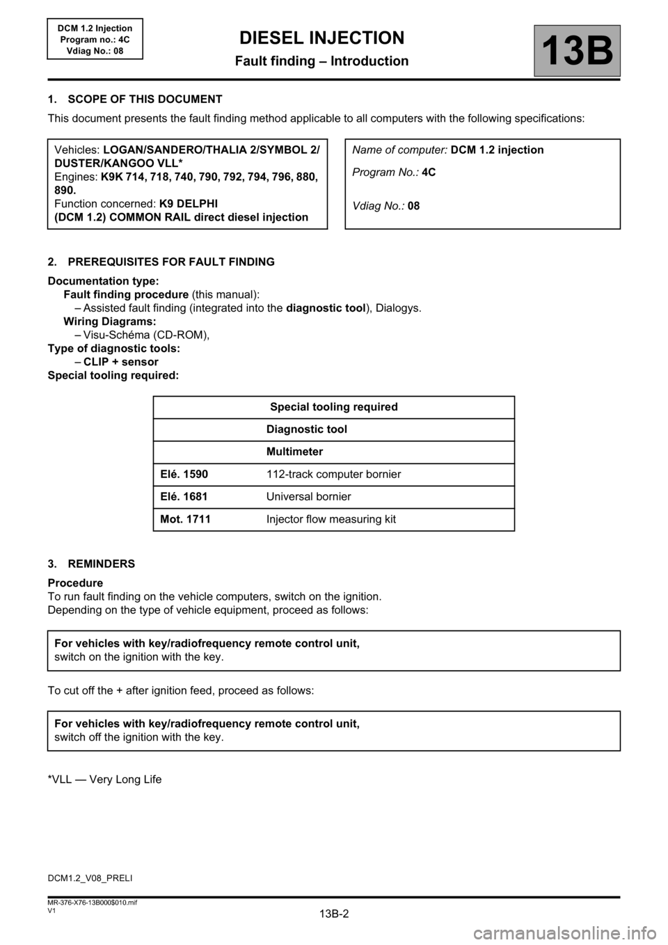
1. SCOPE OF THIS DOCUMENT
This document presents the fault finding method applicable to all computers with the following specifications:
2. PREREQUISITES FOR FAULT FINDING
Documentation type:
Fault finding procedure (this manual):
– Assisted fault finding (integrated into the diagnostic tool), Dialogys.
Wiring Diagrams:
– Visu-Schéma (CD-ROM),
Type of diagnostic tools:
–CLIP + sensor
Special tooling required:
3. REMINDERS
Procedure
To run fault finding on the vehicle computers, switch on the ignition.
Depending on the type of vehicle equipment, proceed as follows:
To cut off the + after ignition feed, proceed as follows:
*VLL — Very Long LifeVehicles: LOGAN/SANDERO/THALIA 2/SYMBOL 2/
DUSTER/KANGOO VLL*
Engines: K9K 714, 718, 740, 790, 792, 794, 796, 880,
890.
Function concerned: K9 DELPHI
(DCM 1.2) COMMON RAIL direct diesel injectionName of computer: DCM 1.2 injection
Program No.: 4C
Vdiag No.: 08
Special tooling required
Diagnostic tool
Multimeter
Elé. 1590112-track computer bornier
Elé. 1681Universal bornier
Mot. 1711Injector flow measuring kit
For vehicles with key/radiofrequency remote control unit,
switch on the ignition with the key.
For vehicles with key/radiofrequency remote control unit,
switch off the ignition with the key.
DCM1.2_V08_PRELI
DIESEL INJECTION
Fault finding – Introduction
Page 37 of 204
13B-37
AFTER REPAIRDeal with any faults declared by the diagnostic tool.
Clear the computer memory.
Carry out a road test followed by another check with the diagnostic tool.
V1 MR-376-X76-13B000$071.mif
DIESEL INJECTION
Fault finding – Interpretation of faults13B
DCM 1.2 Injection
Program no.: 4C
Vdiag No.: 08
DF010
PRESENT
OR
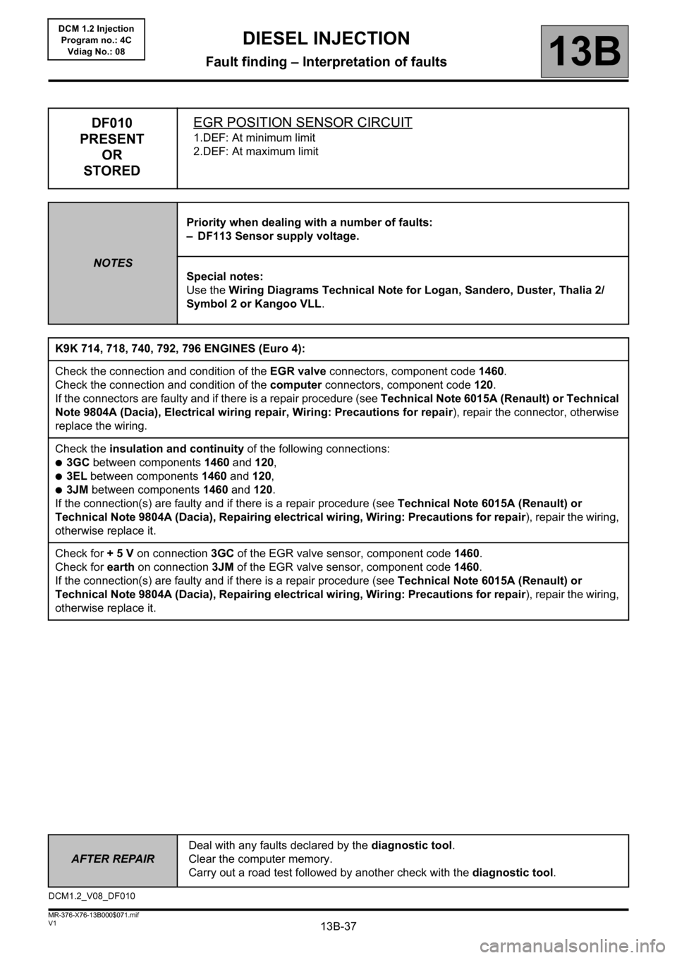
STOREDEGR POSITION SENSOR CIRCUIT
1.DEF: At minimum limit
2.DEF: At maximum limit
NOTESPriority when dealing with a number of faults:
– DF113 Sensor supply voltage.
Special notes:
Use the Wiring Diagrams Technical Note for Logan, Sandero, Duster, Thalia 2/
Symbol 2 or Kangoo VLL.
K9K 714, 718, 740, 792, 796 ENGINES (Euro 4):
Check the connection and condition of the EGR valve connectors, component code 1460.
Check the connection and condition of the computer connectors, component code 120.
If the connectors are faulty and if there is a repair procedure (see Technical Note 6015A (Renault) or Technical
Note 9804A (Dacia), Electrical wiring repair, Wiring: Precautions for repair), repair the connector, otherwise
replace the wiring.
Check the insulation and continuity of the following connections:
●3GC between components 1460 and 120,
●3EL between components 1460 and 120,
●3JM between components 1460 and 120.
If the connection(s) are faulty and if there is a repair procedure (see Technical Note 6015A (Renault) or
Technical Note 9804A (Dacia), Repairing electrical wiring, Wiring: Precautions for repair), repair the wiring,
otherwise replace it.
Check for + 5 V on connection 3GC of the EGR valve sensor, component code 1460.
Check for earth on connection 3JM of the EGR valve sensor, component code 1460.
If the connection(s) are faulty and if there is a repair procedure (see Technical Note 6015A (Renault) or
Technical Note 9804A (Dacia), Repairing electrical wiring, Wiring: Precautions for repair), repair the wiring,
otherwise replace it.
DCM1.2_V08_DF010
Page 46 of 204
13B-46
AFTER REPAIRDeal with any faults declared by the diagnostic tool.
Clear the computer memory.
Carry out a road test followed by another check with the diagnostic tool.
V1 MR-376-X76-13B000$071.mif
DIESEL INJECTION
Fault finding – Interpretation of faults13B
DCM 1.2 Injection
Program no.: 4C
Vdiag No.: 08
DF018
PRESENT
OR
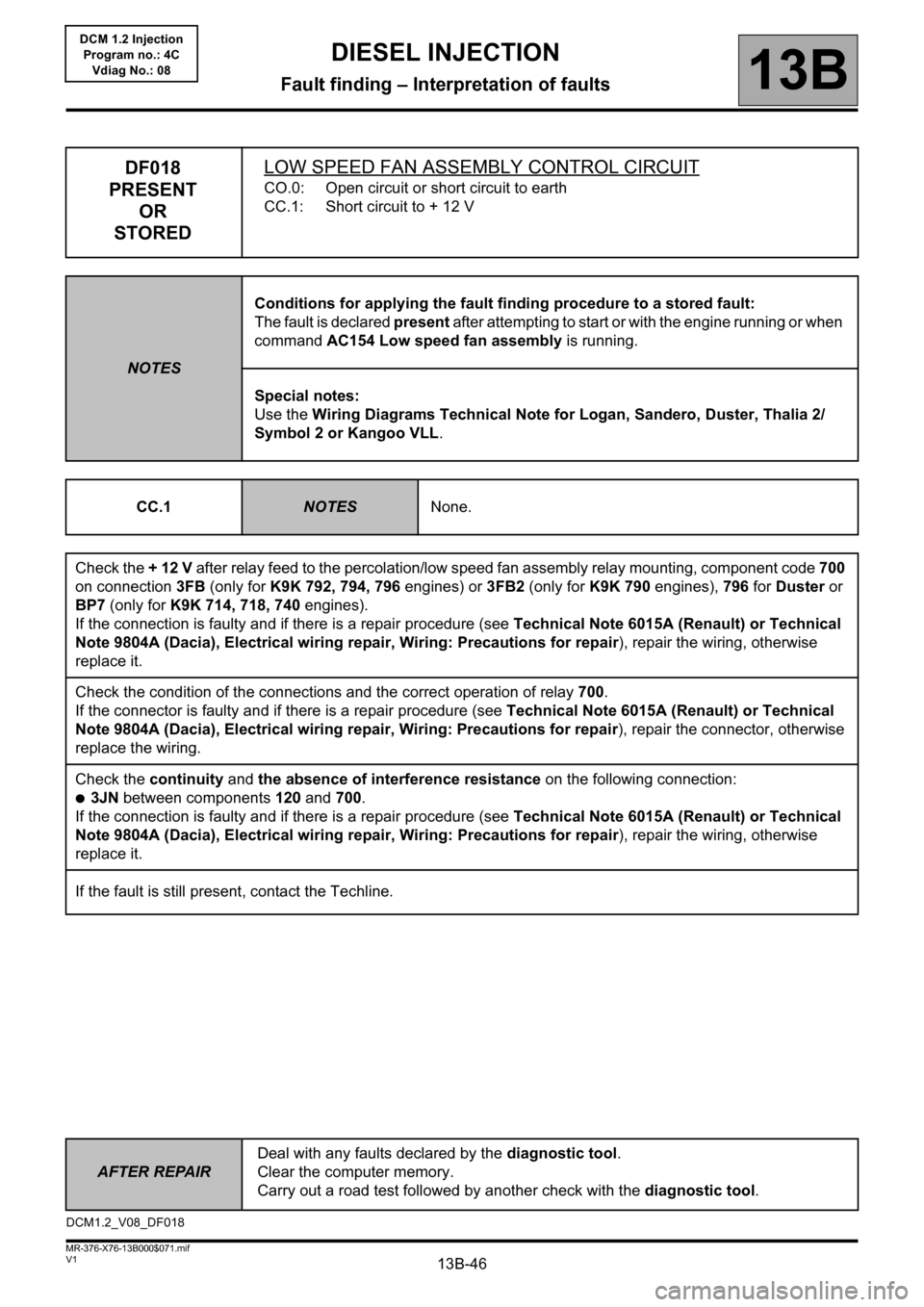
STOREDLOW SPEED FAN ASSEMBLY CONTROL CIRCUIT
CO.0: Open circuit or short circuit to earth
CC.1: Short circuit to + 12 V
NOTESConditions for applying the fault finding procedure to a stored fault:
The fault is declared present after attempting to start or with the engine running or when
command AC154 Low speed fan assembly is running.
Special notes:
Use the Wiring Diagrams Technical Note for Logan, Sandero, Duster, Thalia 2/
Symbol 2 or Kangoo VLL.
CC.1
NOTESNone.
Check the + 12 V after relay feed to the percolation/low speed fan assembly relay mounting, component code 700
on connection 3FB (only for K9K 792, 794, 796 engines) or 3FB2 (only for K9K 790 engines), 796 for Duster or
BP7 (only for K9K 714, 718, 740 engines).
If the connection is faulty and if there is a repair procedure (see Technical Note 6015A (Renault) or Technical
Note 9804A (Dacia), Electrical wiring repair, Wiring: Precautions for repair), repair the wiring, otherwise
replace it.
Check the condition of the connections and the correct operation of relay 700.
If the connector is faulty and if there is a repair procedure (see Technical Note 6015A (Renault) or Technical
Note 9804A (Dacia), Electrical wiring repair, Wiring: Precautions for repair), repair the connector, otherwise
replace the wiring.
Check the continuity and the absence of interference resistance on the following connection:
●3JN between components 120 and 700.
If the connection is faulty and if there is a repair procedure (see Technical Note 6015A (Renault) or Technical
Note 9804A (Dacia), Electrical wiring repair, Wiring: Precautions for repair), repair the wiring, otherwise
replace it.
If the fault is still present, contact the Techline.
DCM1.2_V08_DF018
Page 47 of 204
13B-47
AFTER REPAIRDeal with any faults declared by the diagnostic tool.
Clear the computer memory.
Carry out a road test followed by another check with the diagnostic tool.
V1 MR-376-X76-13B000$071.mif
DIESEL INJECTION
Fault finding – Interpretation of faults13B
DCM 1.2 Injection
Program no.: 4C
Vdiag No.: 08
DF018
CONTINUED
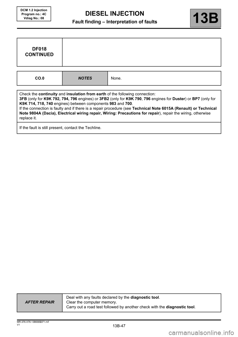
CO.0NOTESNone.
Check the continuity and insulation from earth of the following connection:
3FB (only for K9K 792, 794, 796 engines) or 3FB2 (only for K9K 790, 796 engines for Duster) or BP7 (only for
K9K 714, 718, 740 engines) between components 983 and 700.
If the connection is faulty and if there is a repair procedure (see Technical Note 6015A (Renault) or Technical
Note 9804A (Dacia), Electrical wiring repair, Wiring: Precautions for repair), repair the wiring, otherwise
replace it.
If the fault is still present, contact the Techline.
Page 48 of 204
13B-48
AFTER REPAIRDeal with any faults declared by the diagnostic tool.
Clear the computer memory.
Carry out a road test followed by another check with the diagnostic tool.
V1 MR-376-X76-13B000$071.mif
DIESEL INJECTION
Fault finding – Interpretation of faults13B
DCM 1.2 Injection
Program no.: 4C
Vdiag No.: 08
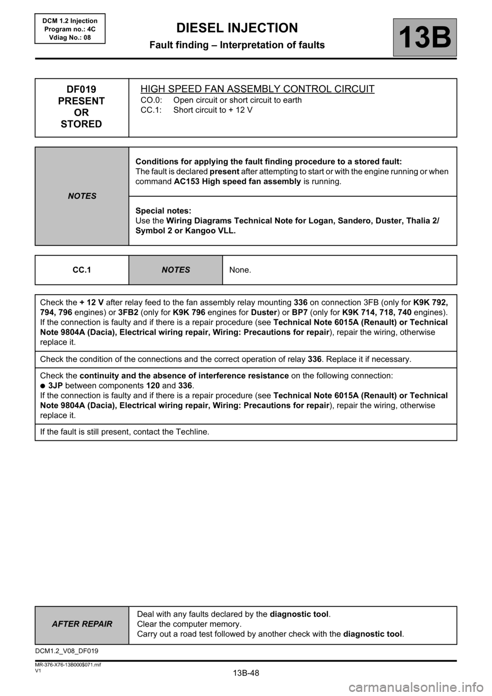
DF019
PRESENT
OR
STOREDHIGH SPEED FAN ASSEMBLY CONTROL CIRCUIT
CO.0: Open circuit or short circuit to earth
CC.1: Short circuit to + 12 V
NOTESConditions for applying the fault finding procedure to a stored fault:
The fault is declared present after attempting to start or with the engine running or when
command AC153 High speed fan assembly is running.
Special notes:
Use the Wiring Diagrams Technical Note for Logan, Sandero, Duster, Thalia 2/
Symbol 2 or Kangoo VLL.
CC.1
NOTESNone.
Check the + 12 V after relay feed to the fan assembly relay mounting 336 on connection 3FB (only for K9K 792,
794, 796 engines) or 3FB2 (only for K9K 796 engines for Duster) or BP7 (only for K9K 714, 718, 740 engines).
If the connection is faulty and if there is a repair procedure (see Technical Note 6015A (Renault) or Technical
Note 9804A (Dacia), Electrical wiring repair, Wiring: Precautions for repair), repair the wiring, otherwise
replace it.
Check the condition of the connections and the correct operation of relay 336. Replace it if necessary.
Check the continuity and the absence of interference resistance on the following connection:
●3JP between components 120 and 336.
If the connection is faulty and if there is a repair procedure (see Technical Note 6015A (Renault) or Technical
Note 9804A (Dacia), Electrical wiring repair, Wiring: Precautions for repair), repair the wiring, otherwise
replace it.
If the fault is still present, contact the Techline.
DCM1.2_V08_DF019
Page 49 of 204
13B-49
AFTER REPAIRDeal with any faults declared by the diagnostic tool.
Clear the computer memory.
Carry out a road test followed by another check with the diagnostic tool.
V1 MR-376-X76-13B000$071.mif
DIESEL INJECTION
Fault finding – Interpretation of faults13B
DCM 1.2 Injection
Program no.: 4C
Vdiag No.: 08
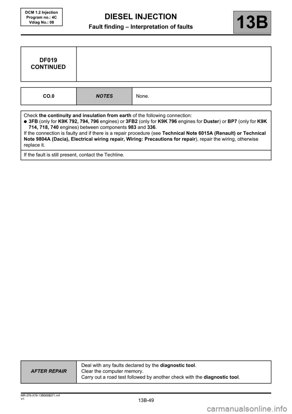
DF019
CONTINUED
CO.0NOTESNone.
Check the continuity and insulation from earth of the following connection:
●3FB (only for K9K 792, 794, 796 engines) or 3FB2 (only for K9K 796 engines for Duster) or BP7 (only for K9K
714, 718, 740 engines) between components 983 and 336.
If the connection is faulty and if there is a repair procedure (see Technical Note 6015A (Renault) or Technical
Note 9804A (Dacia), Electrical wiring repair, Wiring: Precautions for repair), repair the wiring, otherwise
replace it.
If the fault is still present, contact the Techline.
Page 93 of 204
13B-93
AFTER
REPAIRDeal with any faults declared by the diagnostic tool.
Clear the computer memory.
Carry out a road test followed by another check with the diagnostic tool.
V1 MR-376-X76-13B000$072.mif
DIESEL INJECTION
Fault finding – Interpretation of faults13B
DCM 1.2 Injection
Program no.: 4C
Vdiag No.: 08
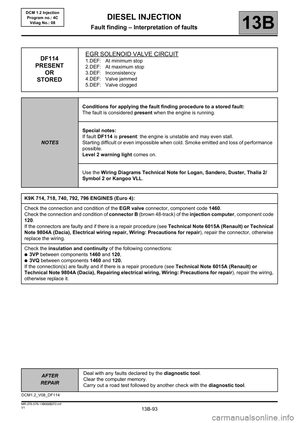
DF114
PRESENT
OR
STOREDEGR SOLENOID VALVE CIRCUIT1.DEF: At minimum stop
2.DEF: At maximum stop
3.DEF: Inconsistency
4.DEF: Valve jammed
5.DEF: Valve clogged
NOTESConditions for applying the fault finding procedure to a stored fault:
The fault is considered present when the engine is running.
Special notes:
If fault DF114 is present: the engine is unstable and may even stall.
Starting difficult or even impossible when cold. Smoke emitted and loss of performance
possible.
Level 2 warning light comes on.
Use the Wiring Diagrams Technical Note for Logan, Sandero, Duster, Thalia 2/
Symbol 2 or Kangoo VLL.
K9K 714, 718, 740, 792, 796 ENGINES (Euro 4):
Check the connection and condition of the EGR valve connector, component code 1460.
Check the connection and condition of connector B (brown 48-track) of the injection computer, component code
120.
If the connectors are faulty and if there is a repair procedure (see Technical Note 6015A (Renault) or Technical
Note 9804A (Dacia), Electrical wiring repair, Wiring: Precautions for repair), repair the connector, otherwise
replace the wiring.
Check the insulation and continuity of the following connections:
●3VP between components 1460 and 120,
●3VQ between components 1460 and 120.
If the connection(s) are faulty and if there is a repair procedure (see Technical Note 6015A (Renault) or
Technical Note 9804A (Dacia), Repairing electrical wiring, Wiring: Precautions for repair), repair the wiring,
otherwise replace it.
DCM1.2_V08_DF114
Page 136 of 204
13B-136
AFTER REPAIRDeal with any faults. Clear the faults from the computer memory.
Switch off the ignition and carry out a road test followed by a test with the diagnostic
tool.
V1 MR-376-X76-13B000$100.mif
13B
DCM 1.2 Injection
Program no.: 4C
Vdiag No.: 08
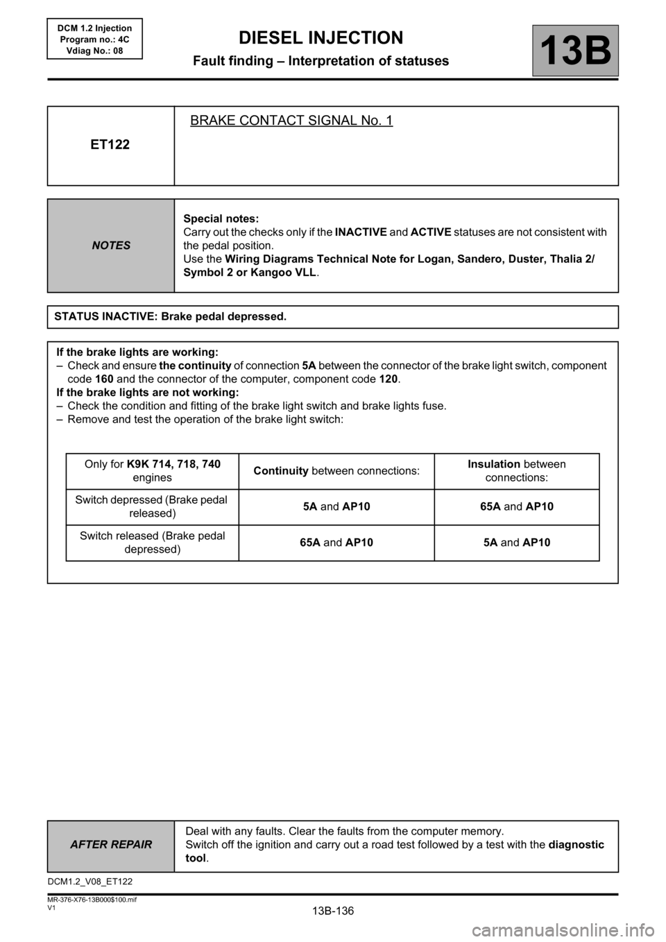
ET122BRAKE CONTACT SIGNAL No. 1
NOTESSpecial notes:
Carry out the checks only if the INACTIVE and ACTIVE statuses are not consistent with
the pedal position.
Use the Wiring Diagrams Technical Note for Logan, Sandero, Duster, Thalia 2/
Symbol 2 or Kangoo VLL.
STATUS INACTIVE: Brake pedal depressed.
If the brake lights are working:
– Check and ensure the continuity of connection 5A between the connector of the brake light switch, component
code 160 and the connector of the computer, component code 120.
If the brake lights are not working:
– Check the condition and fitting of the brake light switch and brake lights fuse.
– Remove and test the operation of the brake light switch:
Only for K9K 714, 718, 740
enginesContinuity between connections:Insulation between
connections:
Switch depressed (Brake pedal
released)5A and AP10 65A and AP10
Switch released (Brake pedal
depressed)65A and AP10 5A and AP10
DCM1.2_V08_ET122
DIESEL INJECTION
Fault finding – Interpretation of statuses
Page 138 of 204
13B-138
AFTER REPAIRDeal with any faults. Clear the faults from the computer memory.
Switch off the ignition and carry out a road test followed by a test with the diagnostic
tool.
V1 MR-376-X76-13B000$100.mif
DIESEL INJECTION
Fault finding – Interpretation of statuses13B
DCM 1.2 Injection
Program no.: 4C
Vdiag No.: 08
ET122
CONTINUED 2
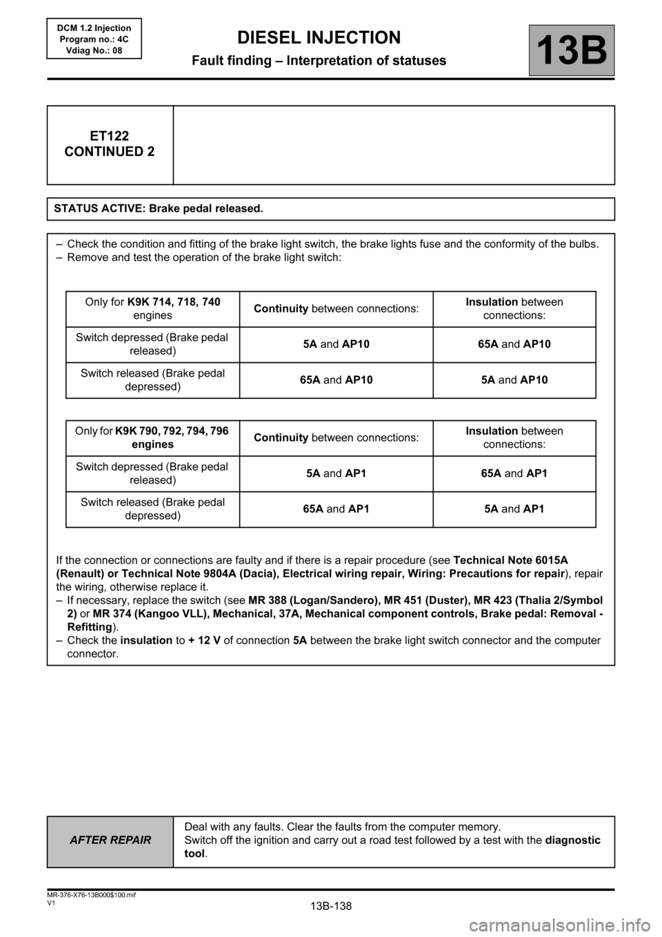
STATUS ACTIVE: Brake pedal released.
– Check the condition and fitting of the brake light switch, the brake lights fuse and the conformity of the bulbs.
– Remove and test the operation of the brake light switch:
Only for K9K 714, 718, 740
enginesContinuity between connections:Insulation between
connections:
Switch depressed (Brake pedal
released)5A and AP10 65A and AP10
Switch released (Brake pedal
depressed)65A and AP10 5A and AP10
Only for K9K 790, 792, 794, 796
enginesContinuity between connections:Insulation between
connections:
Switch depressed (Brake pedal
released)5A and AP1 65A and AP1
Switch released (Brake pedal
depressed)65A and AP1 5A and AP1
If the connection or connections are faulty and if there is a repair procedure (see Technical Note 6015A
(Renault) or Technical Note 9804A (Dacia), Electrical wiring repair, Wiring: Precautions for repair), repair
the wiring, otherwise replace it.
– If necessary, replace the switch (see MR 388 (Logan/Sandero), MR 451 (Duster), MR 423 (Thalia 2/Symbol
2) or MR 374 (Kangoo VLL), Mechanical, 37A, Mechanical component controls, Brake pedal: Removal -
Refitting).
– Check the insulation to + 12 V of connection 5A between the brake light switch connector and the computer
connector.
Page 139 of 204
13B-139
AFTER REPAIRDeal with any faults. Clear the faults from the computer memory.
Switch off the ignition and carry out a road test followed by a test with the diagnostic
tool.
V1 MR-376-X76-13B000$100.mif
DIESEL INJECTION
Fault finding – Interpretation of statuses13B
DCM 1.2 Injection
Program no.: 4C
Vdiag No.: 08
ET233CLUTCH PEDAL
NOTESSpecial notes:
Carry out the checks only if the RELEASED and DEPRESSED statuses are not
consistent with the pedal position.
Use the Wiring Diagrams Technical Note for Logan, Sandero, Duster, Thalia 2/
Symbol 2 or Kangoo VLL.
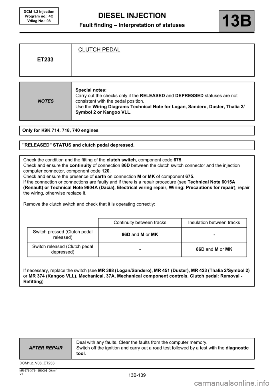
Only for K9K 714, 718, 740 engines
"RELEASED" STATUS and clutch pedal depressed.
Check the condition and the fitting of the clutch switch, component code 675.
Check and ensure the continuity of connection 86D between the clutch switch connector and the injection
computer connector, component code 120.
Check and ensure the presence of earth on connection M or MK of component 675.
If the connection or connections are faulty and if there is a repair procedure (see Technical Note 6015A
(Renault) or Technical Note 9804A (Dacia), Electrical wiring repair, Wiring: Precautions for repair), repair
the wiring, otherwise replace it.
Remove the clutch switch and check that it is operating correctly:
Continuity between tracks Insulation between tracks
Switch pressed (Clutch pedal
released)86D and M or MK -
Switch released (Clutch pedal
depressed)-86D and M or MK
If necessary, replace the switch (see MR 388 (Logan/Sandero), MR 451 (Duster), MR 423 (Thalia 2/Symbol 2)
or MR 374 (Kangoo VLL), Mechanical, 37A, Mechanical component controls, Clutch pedal: Removal -
Refitting).
DCM1.2_V08_ET233