lights RENAULT KANGOO 2013 X61 / 2.G Diesel DCM 1.2 Injection Workshop Manual
[x] Cancel search | Manufacturer: RENAULT, Model Year: 2013, Model line: KANGOO, Model: RENAULT KANGOO 2013 X61 / 2.GPages: 204, PDF Size: 0.99 MB
Page 15 of 204
13B-15V1 MR-376-X76-13B000$030.mif
DIESEL INJECTION
Fault finding – System operation13B
DCM 1.2 Injection
Program no.: 4C
Vdiag No.: 08
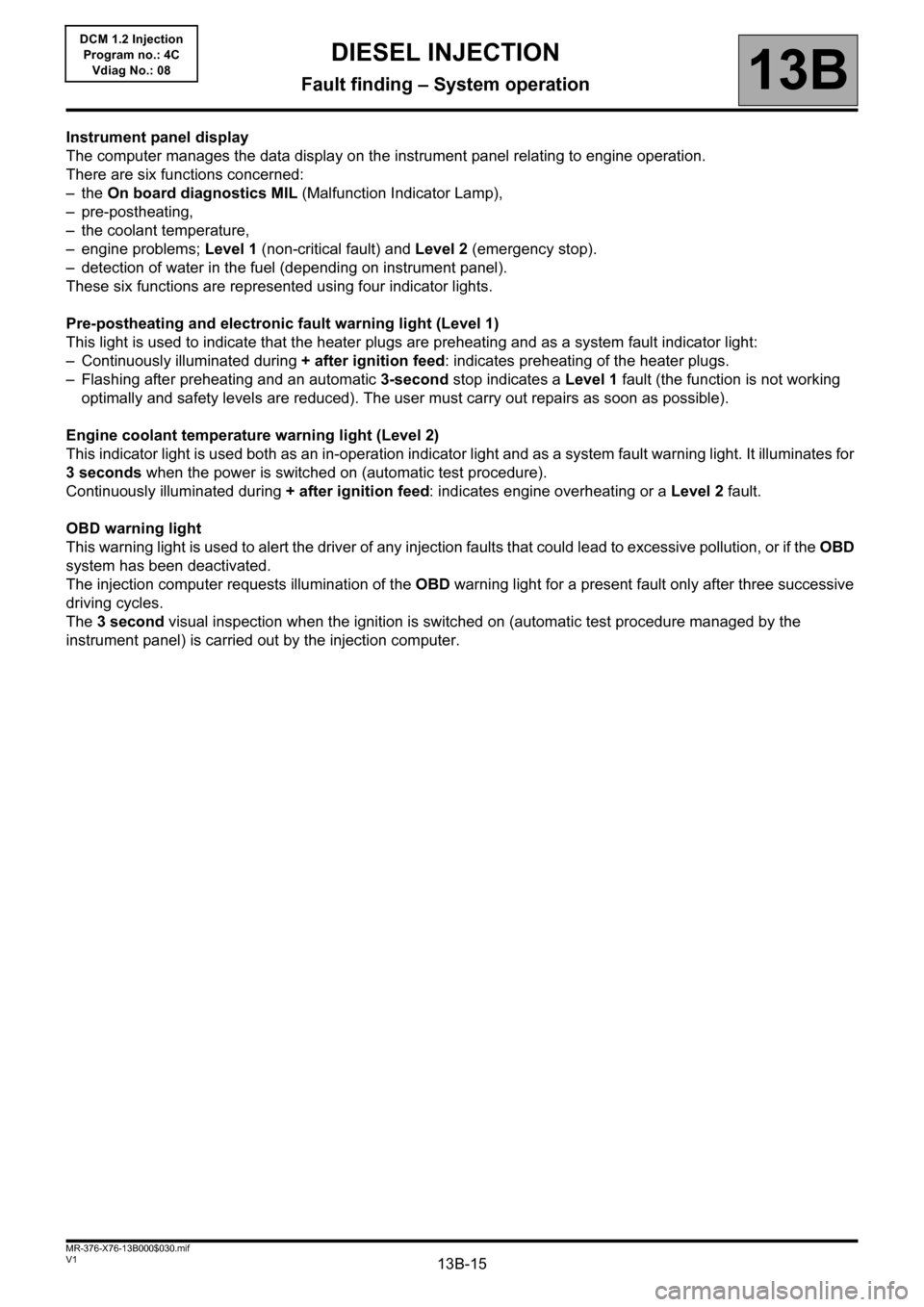
Instrument panel display
The computer manages the data display on the instrument panel relating to engine operation.
There are six functions concerned:
–the On board diagnostics MIL (Malfunction Indicator Lamp),
– pre-postheating,
– the coolant temperature,
– engine problems; Level 1 (non-critical fault) and Level 2 (emergency stop).
– detection of water in the fuel (depending on instrument panel).
These six functions are represented using four indicator lights.
Pre-postheating and electronic fault warning light (Level 1)
This light is used to indicate that the heater plugs are preheating and as a system fault indicator light:
– Continuously illuminated during + after ignition feed: indicates preheating of the heater plugs.
– Flashing after preheating and an automatic 3-second stop indicates a Level 1 fault (the function is not working
optimally and safety levels are reduced). The user must carry out repairs as soon as possible).
Engine coolant temperature warning light (Level 2)
This indicator light is used both as an in-operation indicator light and as a system fault warning light. It illuminates for
3 seconds when the power is switched on (automatic test procedure).
Continuously illuminated during + after ignition feed: indicates engine overheating or a Level 2 fault.
OBD warning light
This warning light is used to alert the driver of any injection faults that could lead to excessive pollution, or if the OBD
system has been deactivated.
The injection computer requests illumination of the OBD warning light for a present fault only after three successive
driving cycles.
The 3 second visual inspection when the ignition is switched on (automatic test procedure managed by the
instrument panel) is carried out by the injection computer.
Page 16 of 204
13B-16V1 MR-376-X76-13B000$030.mif
DIESEL INJECTION
Fault finding – System operation13B
DCM 1.2 Injection
Program no.: 4C
Vdiag No.: 08
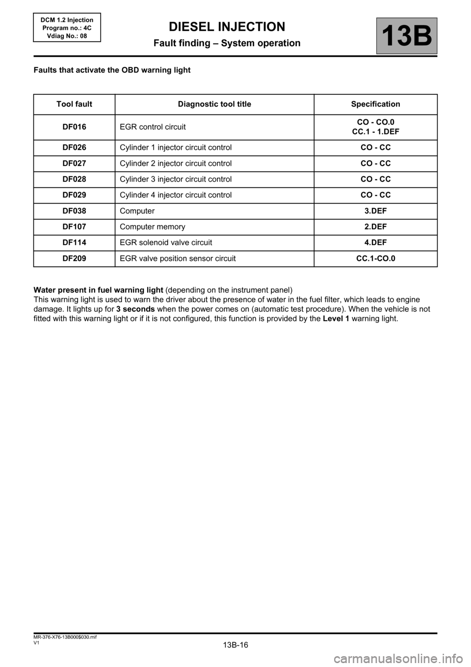
Faults that activate the OBD warning light
Water present in fuel warning light (depending on the instrument panel)
This warning light is used to warn the driver about the presence of water in the fuel filter, which leads to engine
damage. It lights up for 3 seconds when the power comes on (automatic test procedure). When the vehicle is not
fitted with this warning light or if it is not configured, this function is provided by the Level 1 warning light. Tool fault Diagnostic tool title Specification
DF016EGR control circuitCO - CO.0
CC.1 - 1.DEF
DF026Cylinder 1 injector circuit controlCO - CC
DF027Cylinder 2 injector circuit controlCO - CC
DF028Cylinder 3 injector circuit controlCO - CC
DF029Cylinder 4 injector circuit controlCO - CC
DF038Computer3.DEF
DF107Computer memory2.DEF
DF114EGR solenoid valve circuit4.DEF
DF209EGR valve position sensor circuitCC.1-CO.0
Page 17 of 204
13B-17V1 MR-376-X76-13B000$040.mif
13B
DCM 1.2 Injection
Program no.: 4C
Vdiag No.: 08
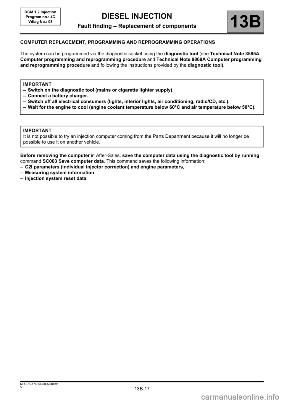
COMPUTER REPLACEMENT, PROGRAMMING AND REPROGRAMMING OPERATIONS
The system can be programmed via the diagnostic socket using the diagnostic tool (see Technical Note 3585A
Computer programming and reprogramming procedure and Technical Note 9869A Computer programming
and reprogramming procedure and following the instructions provided by the diagnostic tool).
Before removing the computer in After-Sales, save the computer data using the diagnostic tool by running
command SC003 Save computer data. This command saves the following information:
–C2I parameters (individual injector correction) and engine parameters,
–Measuring system information,
–Injection system reset data. IMPORTANT
– Switch on the diagnostic tool (mains or cigarette lighter supply).
– Connect a battery charger.
– Switch off all electrical consumers (lights, interior lights, air conditioning, radio/CD, etc.).
– Wait for the engine to cool (engine coolant temperature below 60°C and air temperature below 50°C).
IMPORTANT
It is not possible to try an injection computer coming from the Parts Department because it will no longer be
possible to use it on another vehicle.
DIESEL INJECTION
Fault finding – Replacement of components
Page 136 of 204
13B-136
AFTER REPAIRDeal with any faults. Clear the faults from the computer memory.
Switch off the ignition and carry out a road test followed by a test with the diagnostic
tool.
V1 MR-376-X76-13B000$100.mif
13B
DCM 1.2 Injection
Program no.: 4C
Vdiag No.: 08
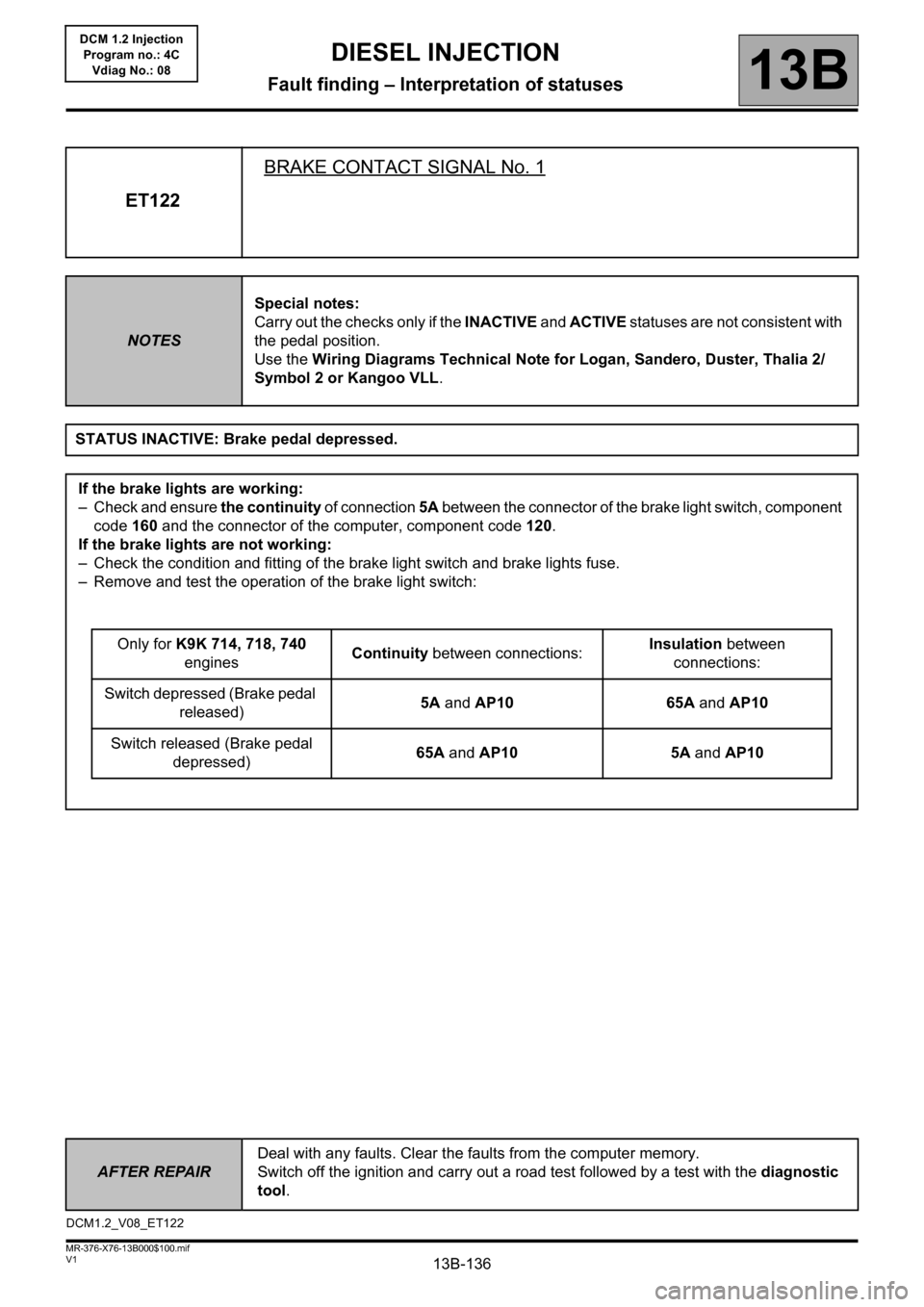
ET122BRAKE CONTACT SIGNAL No. 1
NOTESSpecial notes:
Carry out the checks only if the INACTIVE and ACTIVE statuses are not consistent with
the pedal position.
Use the Wiring Diagrams Technical Note for Logan, Sandero, Duster, Thalia 2/
Symbol 2 or Kangoo VLL.
STATUS INACTIVE: Brake pedal depressed.
If the brake lights are working:
– Check and ensure the continuity of connection 5A between the connector of the brake light switch, component
code 160 and the connector of the computer, component code 120.
If the brake lights are not working:
– Check the condition and fitting of the brake light switch and brake lights fuse.
– Remove and test the operation of the brake light switch:
Only for K9K 714, 718, 740
enginesContinuity between connections:Insulation between
connections:
Switch depressed (Brake pedal
released)5A and AP10 65A and AP10
Switch released (Brake pedal
depressed)65A and AP10 5A and AP10
DCM1.2_V08_ET122
DIESEL INJECTION
Fault finding – Interpretation of statuses
Page 138 of 204
13B-138
AFTER REPAIRDeal with any faults. Clear the faults from the computer memory.
Switch off the ignition and carry out a road test followed by a test with the diagnostic
tool.
V1 MR-376-X76-13B000$100.mif
DIESEL INJECTION
Fault finding – Interpretation of statuses13B
DCM 1.2 Injection
Program no.: 4C
Vdiag No.: 08
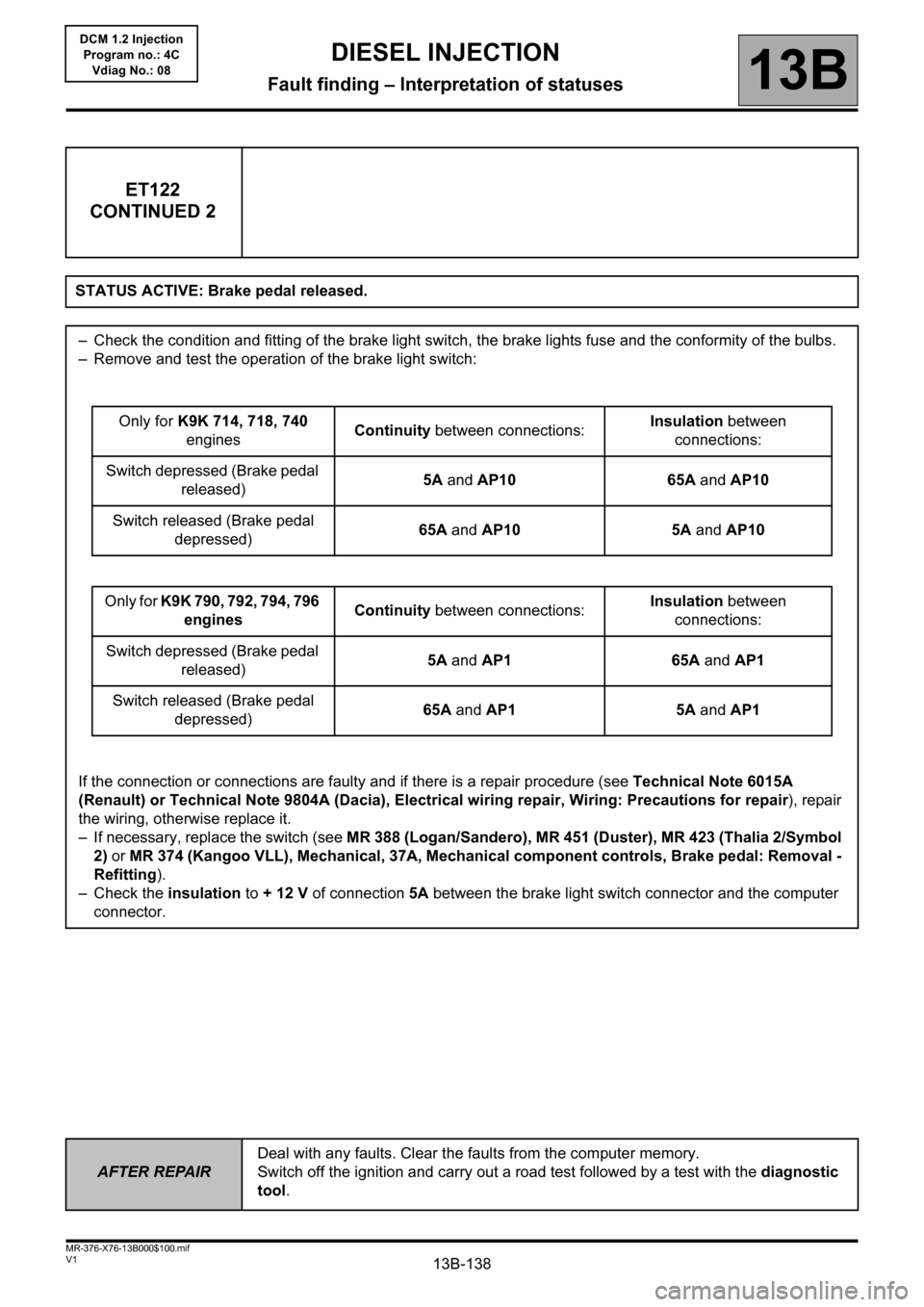
ET122
CONTINUED 2
STATUS ACTIVE: Brake pedal released.
– Check the condition and fitting of the brake light switch, the brake lights fuse and the conformity of the bulbs.
– Remove and test the operation of the brake light switch:
Only for K9K 714, 718, 740
enginesContinuity between connections:Insulation between
connections:
Switch depressed (Brake pedal
released)5A and AP10 65A and AP10
Switch released (Brake pedal
depressed)65A and AP10 5A and AP10
Only for K9K 790, 792, 794, 796
enginesContinuity between connections:Insulation between
connections:
Switch depressed (Brake pedal
released)5A and AP1 65A and AP1
Switch released (Brake pedal
depressed)65A and AP1 5A and AP1
If the connection or connections are faulty and if there is a repair procedure (see Technical Note 6015A
(Renault) or Technical Note 9804A (Dacia), Electrical wiring repair, Wiring: Precautions for repair), repair
the wiring, otherwise replace it.
– If necessary, replace the switch (see MR 388 (Logan/Sandero), MR 451 (Duster), MR 423 (Thalia 2/Symbol
2) or MR 374 (Kangoo VLL), Mechanical, 37A, Mechanical component controls, Brake pedal: Removal -
Refitting).
– Check the insulation to + 12 V of connection 5A between the brake light switch connector and the computer
connector.