speed RENAULT KANGOO 2013 X61 / 2.G Petrol V42 Injection Owner's Manual
[x] Cancel search | Manufacturer: RENAULT, Model Year: 2013, Model line: KANGOO, Model: RENAULT KANGOO 2013 X61 / 2.GPages: 279, PDF Size: 1.29 MB
Page 72 of 279
17B-72
AFTER REPAIRDeal with any faults displayed by the diagnostic tool.
Clear the computer fault memory.
Carry out a road test followed by another check with the diagnostic tool.
V2 MR-376-X76-17B050$082.mif
PETROL INJECTION
Fault finding – Interpretation of faults17B
V42 Injection
Program No.: 2A
Vdiag No.: 04, 05, 06,
14, 16, 18
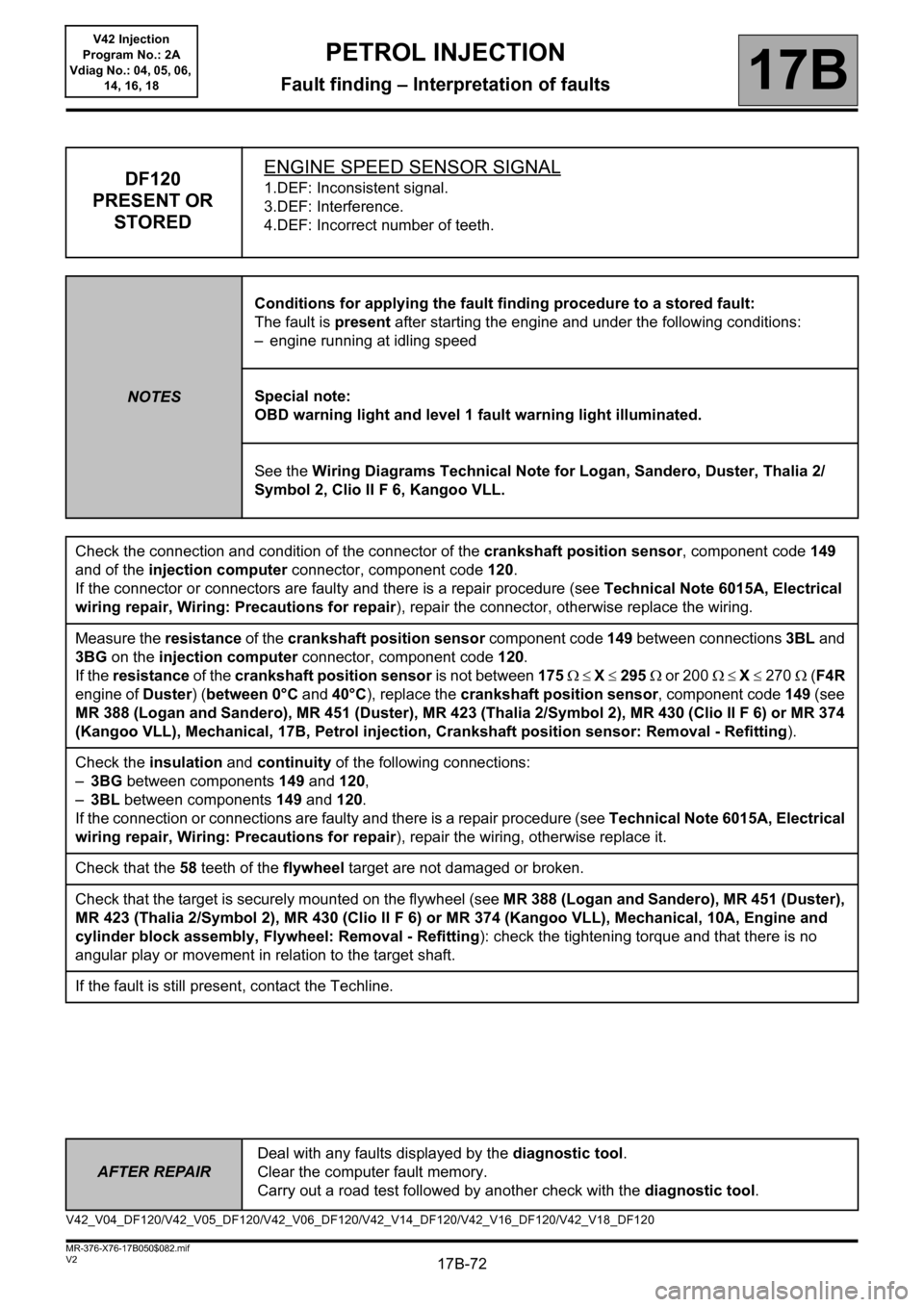
DF120
PRESENT OR
STOREDENGINE SPEED SENSOR SIGNAL1.DEF: Inconsistent signal.
3.DEF: Interference.
4.DEF: Incorrect number of teeth.
NOTESConditions for applying the fault finding procedure to a stored fault:
The fault is present after starting the engine and under the following conditions:
– engine running at idling speed
Special note:
OBD warning light and level 1 fault warning light illuminated.
See the Wiring Diagrams Technical Note for Logan, Sandero, Duster, Thalia 2/
Symbol 2, Clio II F 6, Kangoo VLL.
Check the connection and condition of the connector of the crankshaft position sensor, component code 149
and of the injection computer connector, component code 120.
If the connector or connectors are faulty and there is a repair procedure (see Technical Note 6015A, Electrical
wiring repair, Wiring: Precautions for repair), repair the connector, otherwise replace the wiring.
Measure the resistance of the crankshaft position sensor component code 149 between connections 3BL and
3BG on the injection computer connector, component code 120.
If the resistance of the crankshaft position sensor is not between 175 X 295 or 200 X 270 (F4R
engine of Duster) (between 0°C and 40°C), replace the crankshaft position sensor, component code 149 (see
MR 388 (Logan and Sandero), MR 451 (Duster), MR 423 (Thalia 2/Symbol 2), MR 430 (Clio II F 6) or MR 374
(Kangoo VLL), Mechanical, 17B, Petrol injection, Crankshaft position sensor: Removal - Refitting).
Check the insulation and continuity of the following connections:
–3BG between components 149 and 120,
–3BL between components 149 and 120.
If the connection or connections are faulty and there is a repair procedure (see Technical Note 6015A, Electrical
wiring repair, Wiring: Precautions for repair), repair the wiring, otherwise replace it.
Check that the 58 teeth of the flywheel target are not damaged or broken.
Check that the target is securely mounted on the flywheel (see MR 388 (Logan and Sandero), MR 451 (Duster),
MR 423 (Thalia 2/Symbol 2), MR 430 (Clio II F 6) or MR 374 (Kangoo VLL), Mechanical, 10A, Engine and
cylinder block assembly, Flywheel: Removal - Refitting): check the tightening torque and that there is no
angular play or movement in relation to the target shaft.
If the fault is still present, contact the Techline.
V42_V04_DF120/V42_V05_DF120/V42_V06_DF120/V42_V14_DF120/V42_V16_DF120/V42_V18_DF120
Page 73 of 279
17B-73
AFTER REPAIRDeal with any faults displayed by the diagnostic tool.
Clear the computer fault memory.
Carry out a road test followed by another check with the diagnostic tool.
V2 MR-376-X76-17B050$082.mif
PETROL INJECTION
Fault finding – Interpretation of faults17B
V42 Injection
Program No.: 2A
Vdiag No.: 04, 05, 06,
14, 16, 18
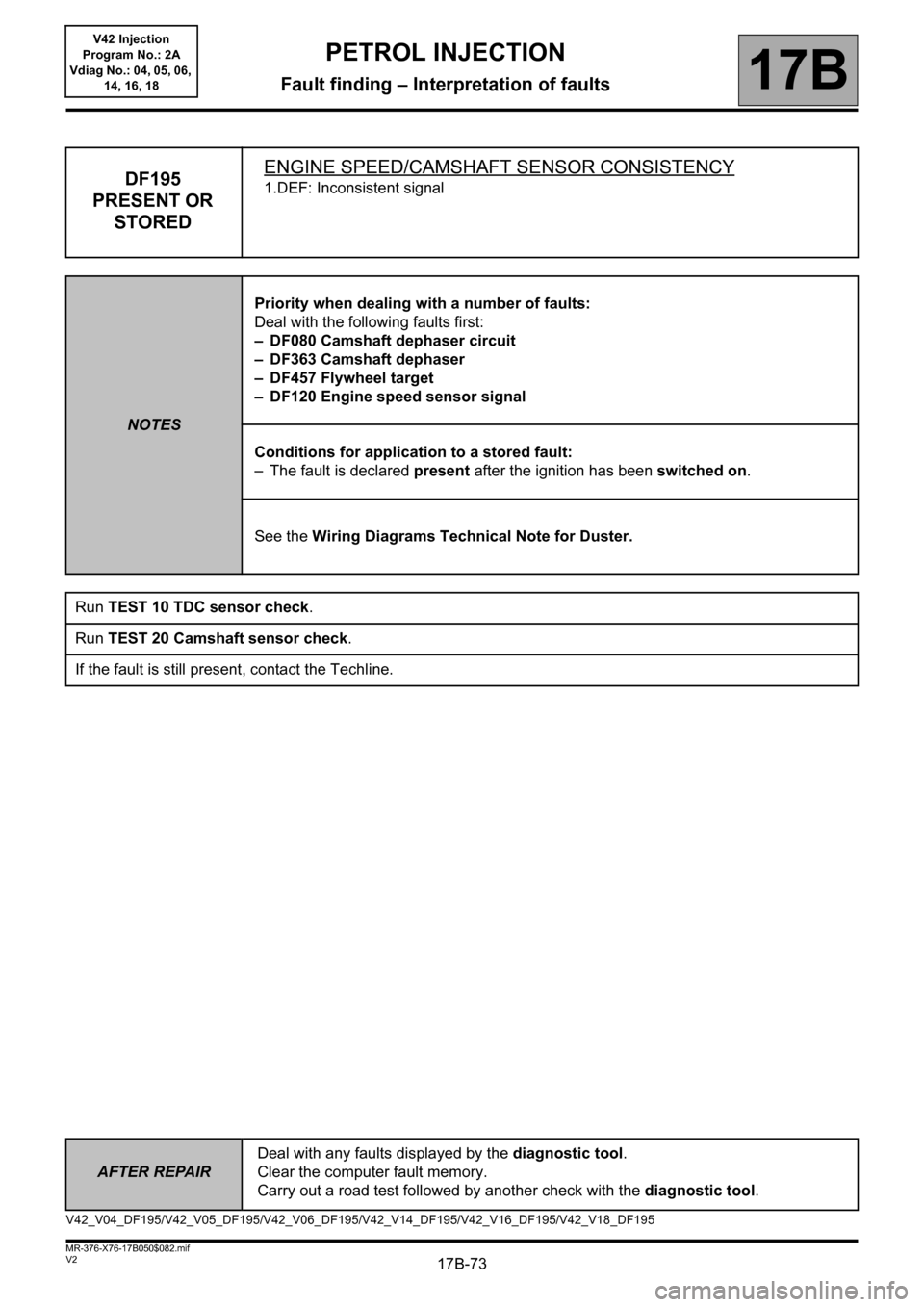
DF195
PRESENT OR
STOREDENGINE SPEED/CAMSHAFT SENSOR CONSISTENCY1.DEF: Inconsistent signal
NOTESPriority when dealing with a number of faults:
Deal with the following faults first:
– DF080 Camshaft dephaser circuit
– DF363 Camshaft dephaser
– DF457 Flywheel target
– DF120 Engine speed sensor signal
Conditions for application to a stored fault:
– The fault is declared present after the ignition has been switched on.
See the Wiring Diagrams Technical Note for Duster.
Run TEST 10 TDC sensor check.
Run TEST 20 Camshaft sensor check.
If the fault is still present, contact the Techline.
V42_V04_DF195/V42_V05_DF195/V42_V06_DF195/V42_V14_DF195/V42_V16_DF195/V42_V18_DF195
Page 74 of 279
17B-74
AFTER REPAIRDeal with any faults displayed by the diagnostic tool.
Clear the computer fault memory.
Carry out a road test followed by another check with the diagnostic tool.
V2 MR-376-X76-17B050$082.mif
PETROL INJECTION
Fault finding – Interpretation of faults17B
V42 Injection
Program No.: 2A
Vdiag No.: 04, 05, 06,
14, 16, 18
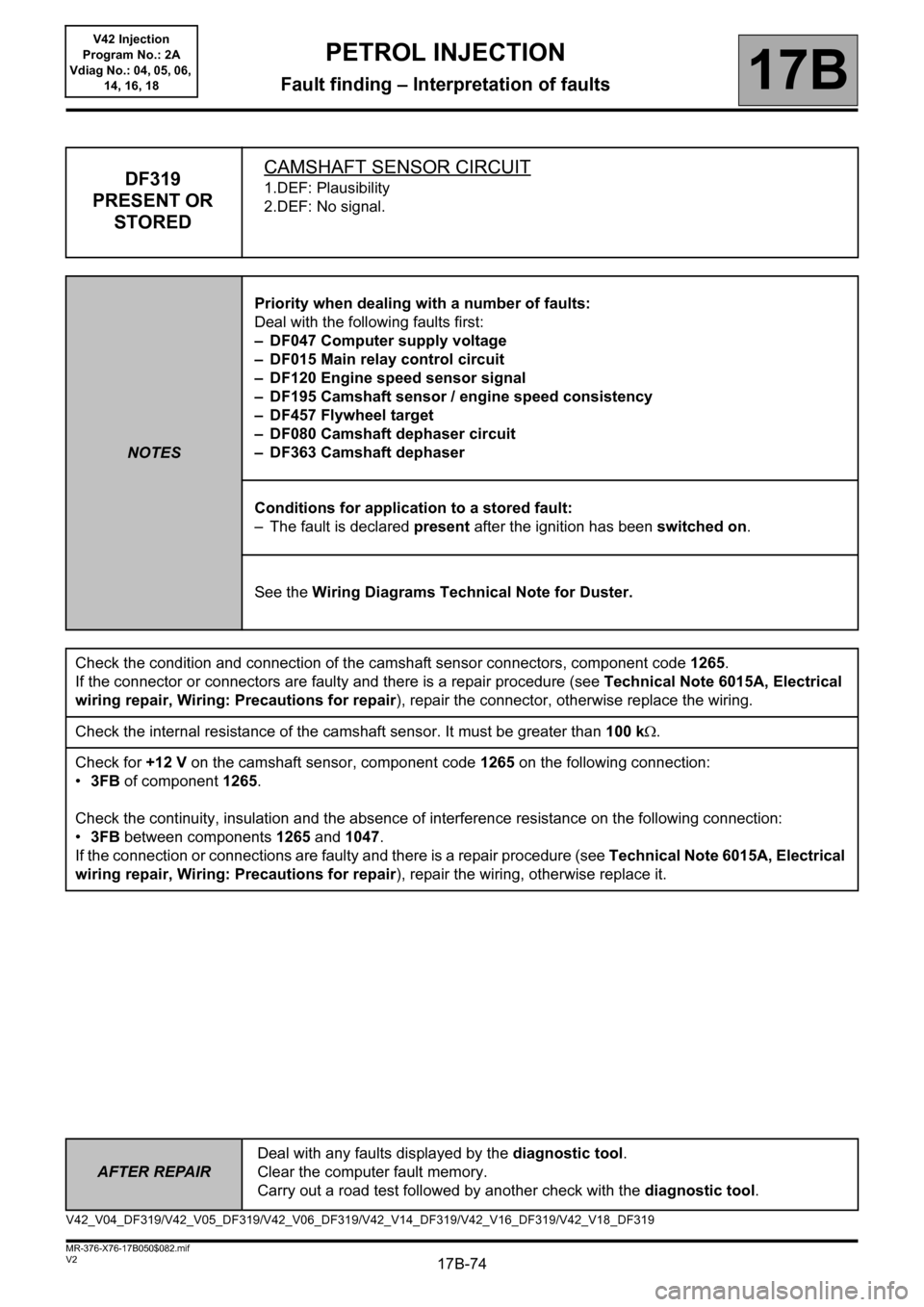
DF319
PRESENT OR
STOREDCAMSHAFT SENSOR CIRCUIT1.DEF: Plausibility
2.DEF: No signal.
NOTESPriority when dealing with a number of faults:
Deal with the following faults first:
– DF047 Computer supply voltage
– DF015 Main relay control circuit
– DF120 Engine speed sensor signal
– DF195 Camshaft sensor / engine speed consistency
– DF457 Flywheel target
– DF080 Camshaft dephaser circuit
– DF363 Camshaft dephaser
Conditions for application to a stored fault:
– The fault is declared present after the ignition has been switched on.
See the Wiring Diagrams Technical Note for Duster.
Check the condition and connection of the camshaft sensor connectors, component code 1265.
If the connector or connectors are faulty and there is a repair procedure (see Technical Note 6015A, Electrical
wiring repair, Wiring: Precautions for repair), repair the connector, otherwise replace the wiring.
Check the internal resistance of the camshaft sensor. It must be greater than 100 k.
Check for +12 V on the camshaft sensor, component code 1265 on the following connection:
•3FB of component 1265.
Check the continuity, insulation and the absence of interference resistance on the following connection:
•3FB between components 1265 and 1047.
If the connection or connections are faulty and there is a repair procedure (see Technical Note 6015A, Electrical
wiring repair, Wiring: Precautions for repair), repair the wiring, otherwise replace it.
V42_V04_DF319/V42_V05_DF319/V42_V06_DF319/V42_V14_DF319/V42_V16_DF319/V42_V18_DF319
Page 79 of 279
17B-79V2 MR-376-X76-17B050$082.mif
PETROL INJECTION
Fault finding – Interpretation of faults17B
V42 Injection
Program No.: 2A
Vdiag No.: 04, 05, 06,
14, 16, 18
AFTER REPAIRFollow the instructions to confirm repair.
Deal with any other faults.
Clear the stored faults.
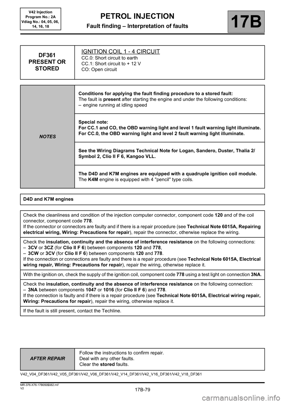
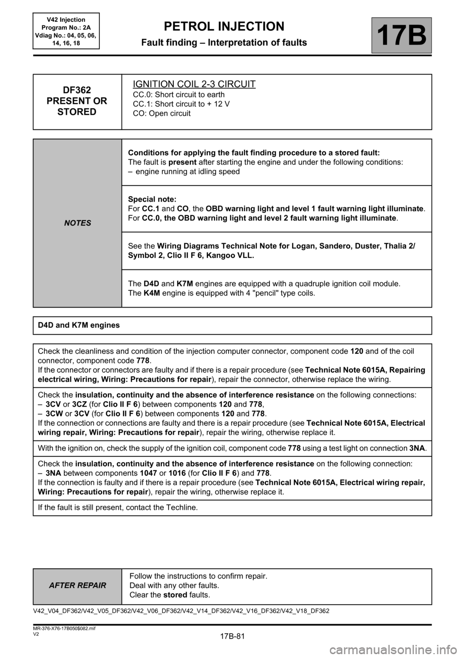
DF361
PRESENT OR
STOREDIGNITION COIL 1 - 4 CIRCUITCC.0: Short circuit to earth
CC.1: Short circuit to + 12 V
CO: Open circuit
NOTESConditions for applying the fault finding procedure to a stored fault:
The fault is present after starting the engine and under the following conditions:
– engine running at idling speed
Special note:
For CC.1 and CO, the OBD warning light and level 1 fault warning light illuminate.
For CC.0, the OBD warning light and level 2 fault warning light illuminate.
See the Wiring Diagrams Technical Note for Logan, Sandero, Duster, Thalia 2/
Symbol 2, Clio II F 6, Kangoo VLL.
The D4D and K7M engines are equipped with a quadruple ignition coil module.
The K4M engine is equipped with 4 "pencil" type coils.
D4D and K7M engines
Check the cleanliness and condition of the injection computer connector, component code 120 and of the coil
connector, component code 778.
If the connector or connectors are faulty and if there is a repair procedure (see Technical Note 6015A, Repairing
electrical wiring, Wiring: Precautions for repair), repair the connector, otherwise replace the wiring.
Check the insulation, continuity and the absence of interference resistance on the following connections:
–3CV or 3CZ (for Clio II F 6) between components 120 and 778,
–3CW or 3CV (for Clio II F 6) between components 120 and 778.
If the connection or connections are faulty and there is a repair procedure (see Technical Note 6015A, Electrical
wiring repair, Wiring: Precautions for repair), repair the wiring, otherwise replace it.
With the ignition on, check the supply of the ignition coil, component code 778 using a test light on connection 3NA.
Check the insulation, continuity and the absence of interference resistance on the following connection:
–3NA between components 1047 or 1016 (for Clio II F 6) and 778.
If the connection is faulty and if there is a repair procedure (see Technical Note 6015A, Electrical wiring repair,
Wiring: Precautions for repair), repair the wiring, otherwise replace it.
If the fault is still present, contact the Techline.
V42_V04_DF361/V42_V05_DF361/V42_V06_DF361/V42_V14_DF361/V42_V16_DF361/V42_V18_DF361
Page 81 of 279
17B-81V2 MR-376-X76-17B050$082.mif
PETROL INJECTION
Fault finding – Interpretation of faults17B
V42 Injection
Program No.: 2A
Vdiag No.: 04, 05, 06,
14, 16, 18
AFTER REPAIRFollow the instructions to confirm repair.
Deal with any other faults.
Clear the stored faults.
DF362
PRESENT OR
STOREDIGNITION COIL 2-3 CIRCUITCC.0: Short circuit to earth
CC.1: Short circuit to + 12 V
CO: Open circuit
NOTESConditions for applying the fault finding procedure to a stored fault:
The fault is present after starting the engine and under the following conditions:
– engine running at idling speed
Special note:
For CC.1 and CO, the OBD warning light and level 1 fault warning light illuminate.
For CC.0, the OBD warning light and level 2 fault warning light illuminate.
See the Wiring Diagrams Technical Note for Logan, Sandero, Duster, Thalia 2/
Symbol 2, Clio II F 6, Kangoo VLL.
The D4D and K7M engines are equipped with a quadruple ignition coil module.
The K4M engine is equipped with 4 "pencil" type coils.
D4D and K7M engines
Check the cleanliness and condition of the injection computer connector, component code 120 and of the coil
connector, component code 778.
If the connector or connectors are faulty and if there is a repair procedure (see Technical Note 6015A, Repairing
electrical wiring, Wiring: Precautions for repair), repair the connector, otherwise replace the wiring.
Check the insulation, continuity and the absence of interference resistance on the following connections:
–3CV or 3CZ (for Clio II F 6) between components 120 and 778,
–3CW or 3CV (for Clio II F 6) between components 120 and 778.
If the connection or connections are faulty and there is a repair procedure (see Technical Note 6015A, Electrical
wiring repair, Wiring: Precautions for repair), repair the wiring, otherwise replace it.
With the ignition on, check the supply of the ignition coil, component code 778 using a test light on connection 3NA.
Check the insulation, continuity and the absence of interference resistance on the following connection:
–3NA between components 1047 or 1016 (for Clio II F 6) and 778.
If the connection is faulty and if there is a repair procedure (see Technical Note 6015A, Electrical wiring repair,
Wiring: Precautions for repair), repair the wiring, otherwise replace it.
If the fault is still present, contact the Techline.
V42_V04_DF362/V42_V05_DF362/V42_V06_DF362/V42_V14_DF362/V42_V16_DF362/V42_V18_DF362
Page 83 of 279
17B-83
AFTER REPAIRDeal with any faults displayed by the diagnostic tool.
Clear the computer fault memory.
Carry out a road test followed by another check with the diagnostic tool.
V2 MR-376-X76-17B050$082.mif
PETROL INJECTION
Fault finding – Interpretation of faults17B
V42 Injection
Program No.: 2A
Vdiag No.: 04, 05, 06,
14, 16, 18
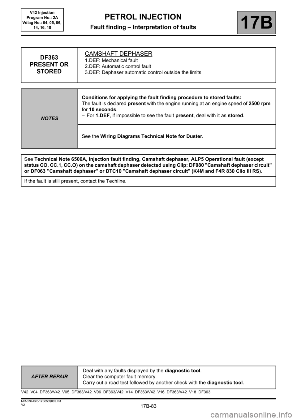
DF363
PRESENT OR
STOREDCAMSHAFT DEPHASER1.DEF: Mechanical fault
2.DEF: Automatic control fault
3.DEF: Dephaser automatic control outside the limits
NOTESConditions for applying the fault finding procedure to stored faults:
The fault is declared present with the engine running at an engine speed of 2500 rpm
for 10 seconds.
–For 1.DEF, if impossible to see the fault present, deal with it as stored.
See the Wiring Diagrams Technical Note for Duster.
See Technical Note 6506A, Injection fault finding, Camshaft dephaser, ALP5 Operational fault (except
status CO, CC.1, CC.O) on the camshaft dephaser detected using Clip: DF080 "Camshaft dephaser circuit"
or DF063 "Camshaft dephaser" or DTC10 "Camshaft dephaser circuit" (K4M and F4R 830 Clio III RS).
If the fault is still present, contact the Techline.
V42_V04_DF363/V42_V05_DF363/V42_V06_DF363/V42_V14_DF363/V42_V16_DF363/V42_V18_DF363
Page 88 of 279
17B-88V2 MR-376-X76-17B050$082.mif
PETROL INJECTION
Fault finding – Interpretation of faults17B
V42 Injection
Program No.: 2A
Vdiag No.: 04, 05, 06,
14, 16, 18
AFTER REPAIRFollow the instructions to confirm repair.
Deal with any other faults.
Clear the stored faults.
*TDC: Top Dead Centre
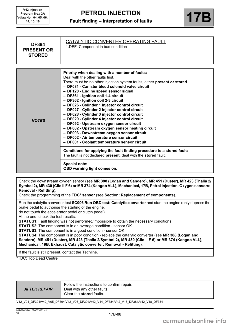
DF394
PRESENT OR
STOREDCATALYTIC CONVERTER OPERATING FAULT1.DEF: Component in bad condition
NOTESPriority when dealing with a number of faults:
Deal with the other faults first.
There must be no other injection system faults, either present or stored.
– DF081 - Canister bleed solenoid valve circuit
– DF120 - Engine speed sensor signal
– DF361 - Ignition coil 1-4 circuit
– DF362 - Ignition coil 2-3 circuit
– DF026 - Cylinder 1 injector control circuit
– DF027 - Cylinder 2 injector control circuit
– DF028 - Cylinder 3 injector control circuit
– DF029 - Cylinder 4 injector control circuit
– DF092 - Upstream oxygen sensor circuit
– DF082 - Upstream oxygen sensor heating circuit
– DF093 - Downstream oxygen sensor circuit
– DF002 - Air temperature sensor circuit
– DF001 - Coolant temperature sensor circuit
Conditions for applying the fault finding procedure to a stored fault:
The fault is not declared present, deal with the stored fault.
Special note:
OBD warning light comes on.
Check the downstream oxygen sensor (see MR 388 (Logan and Sandero), MR 451 (Duster), MR 423 (Thalia 2/
Symbol 2), MR 430 (Clio II F 6) or MR 374 (Kangoo VLL), Mechanical, 17B, Petrol injection, Oxygen sensors:
Removal - Refitting).
Check the programming of the TDC* sensor (see Section: Replacement of components).
Run the catalytic converter test SC006 Run OBD test: Catalytic converter and start the engine (only depress the
brake pedal to authorise the starting of the engine,
do not touch the accelerator pedal or clutch pedal).
At the end, check the test results:
STATUS1: Fault finding was not performed/impossible to obtain the necessary conditions
STATUS2: The component is in an average condition - sensor OK
STATUS3: The component is in a good condition - sensor OK
STATUS4: The component is in poor condition - replace the catalytic converter (see MR 388 (Logan and
Sandero), MR 451 (Duster), MR 423 (Thalia 2/Symbol 2), MR 430 (Clio II F 6) or MR 374 (Kangoo VLL),
Mechanical, 19B, Exhaust, Catalytic converter: Removal - Refitting).
If the fault is still present, contact the Techline.
V42_V04_DF394/V42_V05_DF394/V42_V06_DF394/V42_V14_DF384/V42_V16_DF384/V42_V18_DF384
Page 89 of 279
17B-89V2 MR-376-X76-17B050$082.mif
PETROL INJECTION
Fault finding – Interpretation of faults17B
V42 Injection
Program No.: 2A
Vdiag No.: 04, 05, 06,
14, 16, 18
AFTER REPAIRFollow the instructions to confirm repair.
Deal with any other faults.
Clear the stored faults.
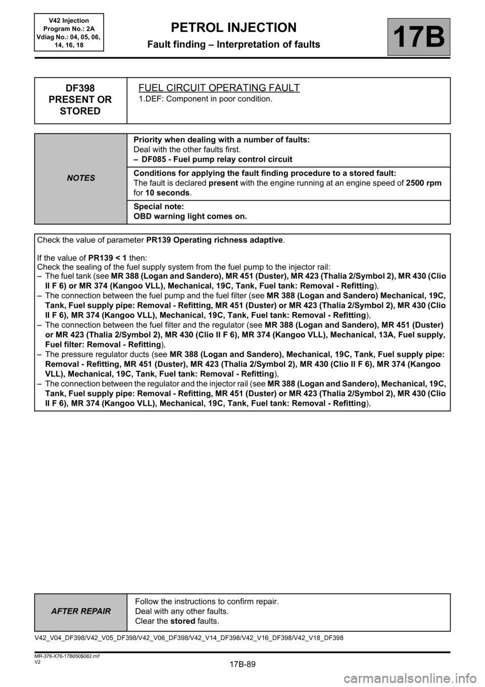
DF398
PRESENT OR
STOREDFUEL CIRCUIT OPERATING FAULT
1.DEF: Component in poor condition.
NOTESPriority when dealing with a number of faults:
Deal with the other faults first.
– DF085 - Fuel pump relay control circuit
Conditions for applying the fault finding procedure to a stored fault:
The fault is declared present with the engine running at an engine speed of 2500 rpm
for 10 seconds.
Special note:
OBD warning light comes on.
Check the value of parameter PR139 Operating richness adaptive.
If the value of PR139 < 1 then:
Check the sealing of the fuel supply system from the fuel pump to the injector rail:
– The fuel tank (see MR 388 (Logan and Sandero), MR 451 (Duster), MR 423 (Thalia 2/Symbol 2), MR 430 (Clio
II F 6) or MR 374 (Kangoo VLL), Mechanical, 19C, Tank, Fuel tank: Removal - Refitting),
– The connection between the fuel pump and the fuel filter (see MR 388 (Logan and Sandero) Mechanical, 19C,
Tank, Fuel supply pipe: Removal - Refitting, MR 451 (Duster) or MR 423 (Thalia 2/Symbol 2), MR 430 (Clio
II F 6), MR 374 (Kangoo VLL), Mechanical, 19C, Tank, Fuel tank: Removal - Refitting),
– The connection between the fuel filter and the regulator (see MR 388 (Logan and Sandero), MR 451 (Duster)
or MR 423 (Thalia 2/Symbol 2), MR 430 (Clio II F 6), MR 374 (Kangoo VLL), Mechanical, 13A, Fuel supply,
Fuel filter: Removal - Refitting),
– The pressure regulator ducts (see MR 388 (Logan and Sandero), Mechanical, 19C, Tank, Fuel supply pipe:
Removal - Refitting, MR 451 (Duster), MR 423 (Thalia 2/Symbol 2), MR 430 (Clio II F 6), MR 374 (Kangoo
VLL), Mechanical, 19C, Tank, Fuel tank: Removal - Refitting),
– The connection between the regulator and the injector rail (see MR 388 (Logan and Sandero), Mechanical, 19C,
Tank, Fuel supply pipe: Removal - Refitting, MR 451 (Duster) or MR 423 (Thalia 2/Symbol 2), MR 430 (Clio
II F 6), MR 374 (Kangoo VLL), Mechanical, 19C, Tank, Fuel tank: Removal - Refitting),
V42_V04_DF398/V42_V05_DF398/V42_V06_DF398/V42_V14_DF398/V42_V16_DF398/V42_V18_DF398
Page 93 of 279
17B-93
AFTER REPAIRFollow the instructions to confirm repair.
Deal with any other faults.
Clear the stored faults.
V2 MR-376-X76-17B050$083.mif
PETROL INJECTION
Fault finding – Interpretation of faults17B
V42 Injection
Program No.: 2A
Vdiag No.: 18
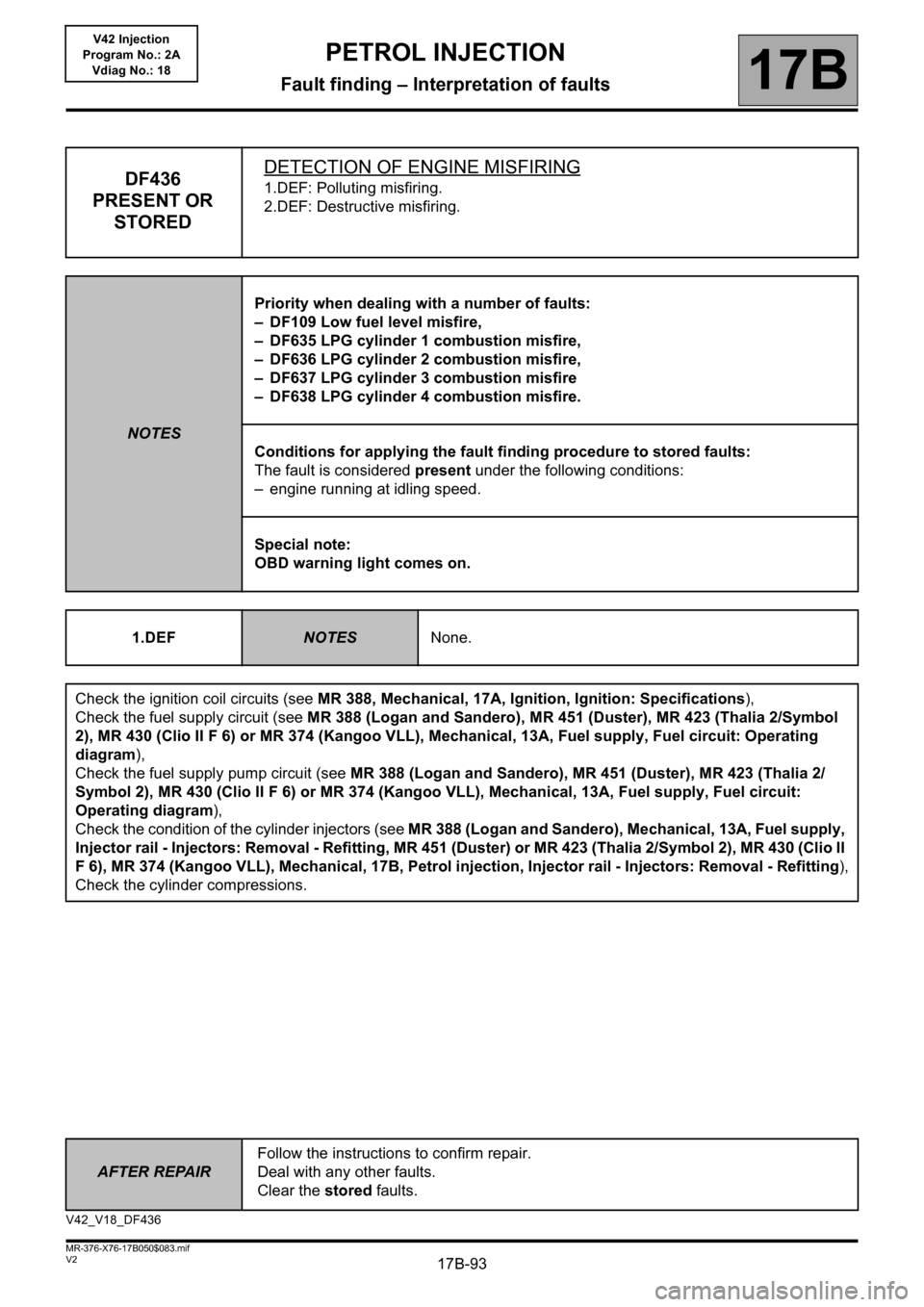
DF436
PRESENT OR
STOREDDETECTION OF ENGINE MISFIRING1.DEF: Polluting misfiring.
2.DEF: Destructive misfiring.
NOTESPriority when dealing with a number of faults:
– DF109 Low fuel level misfire,
– DF635 LPG cylinder 1 combustion misfire,
– DF636 LPG cylinder 2 combustion misfire,
– DF637 LPG cylinder 3 combustion misfire
– DF638 LPG cylinder 4 combustion misfire.
Conditions for applying the fault finding procedure to stored faults:
The fault is considered present under the following conditions:
– engine running at idling speed.
Special note:
OBD warning light comes on.
1.DEF
NOTESNone.
Check the ignition coil circuits (see MR 388, Mechanical, 17A, Ignition, Ignition: Specifications),
Check the fuel supply circuit (see MR 388 (Logan and Sandero), MR 451 (Duster), MR 423 (Thalia 2/Symbol
2), MR 430 (Clio II F 6) or MR 374 (Kangoo VLL), Mechanical, 13A, Fuel supply, Fuel circuit: Operating
diagram),
Check the fuel supply pump circuit (see MR 388 (Logan and Sandero), MR 451 (Duster), MR 423 (Thalia 2/
Symbol 2), MR 430 (Clio II F 6) or MR 374 (Kangoo VLL), Mechanical, 13A, Fuel supply, Fuel circuit:
Operating diagram),
Check the condition of the cylinder injectors (see MR 388 (Logan and Sandero), Mechanical, 13A, Fuel supply,
Injector rail - Injectors: Removal - Refitting, MR 451 (Duster) or MR 423 (Thalia 2/Symbol 2), MR 430 (Clio II
F 6), MR 374 (Kangoo VLL), Mechanical, 17B, Petrol injection, Injector rail - Injectors: Removal - Refitting),
Check the cylinder compressions.
V42_V18_DF436
Page 96 of 279
17B-96V2 MR-376-X76-17B050$083.mif
PETROL INJECTION
Fault finding – Interpretation of faults17B
V42 Injection
Program No.: 2A
Vdiag No.: 04, 05, 06,
14, 16, 18
AFTER REPAIRFollow the instructions to confirm repair.
Deal with any other faults.
Clear the stored faults.
*TDC: Top Dead Centre
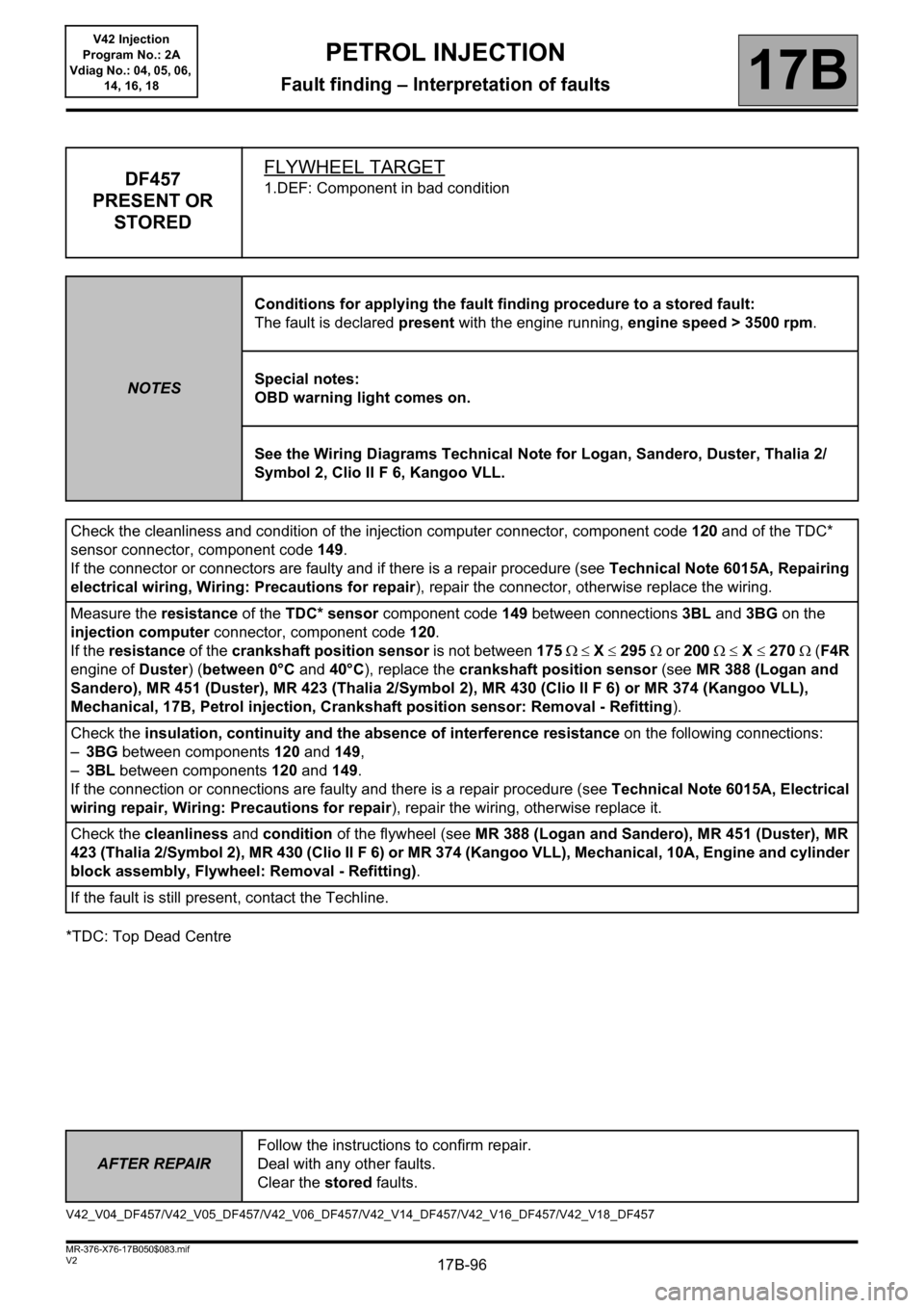
DF457
PRESENT OR
STOREDFLYWHEEL TARGET1.DEF: Component in bad condition
NOTESConditions for applying the fault finding procedure to a stored fault:
The fault is declared present with the engine running, engine speed > 3500 rpm.
Special notes:
OBD warning light comes on.
See the Wiring Diagrams Technical Note for Logan, Sandero, Duster, Thalia 2/
Symbol 2, Clio II F 6, Kangoo VLL.
Check the cleanliness and condition of the injection computer connector, component code 120 and of the TDC*
sensor connector, component code 149.
If the connector or connectors are faulty and if there is a repair procedure (see Technical Note 6015A, Repairing
electrical wiring, Wiring: Precautions for repair), repair the connector, otherwise replace the wiring.
Measure the resistance of the TDC* sensor component code 149 between connections 3BL and 3BG on the
injection computer connector, component code 120.
If the resistance of the crankshaft position sensor is not between 175 X 295 or 200 X 270 (F4R
engine of Duster) (between 0°C and 40°C), replace the crankshaft position sensor (see MR 388 (Logan and
Sandero), MR 451 (Duster), MR 423 (Thalia 2/Symbol 2), MR 430 (Clio II F 6) or MR 374 (Kangoo VLL),
Mechanical, 17B, Petrol injection, Crankshaft position sensor: Removal - Refitting).
Check the insulation, continuity and the absence of interference resistance on the following connections:
–3BG between components 120 and 149,
–3BL between components 120 and 149.
If the connection or connections are faulty and there is a repair procedure (see Technical Note 6015A, Electrical
wiring repair, Wiring: Precautions for repair),
repair the wiring, otherwise replace it.
Check the cleanliness and condition of the flywheel (see MR 388 (Logan and Sandero), MR 451 (Duster), MR
423 (Thalia 2/Symbol 2), MR 430 (Clio II F 6) or MR 374 (Kangoo VLL), Mechanical, 10A, Engine and cylinder
block assembly, Flywheel: Removal - Refitting).
If the fault is still present, contact the Techline.
V42_V04_DF457/V42_V05_DF457/V42_V06_DF457/V42_V14_DF457/V42_V16_DF457/V42_V18_DF457