speed RENAULT KANGOO 2013 X61 / 2.G Petrol V42 Injection Repair Manual
[x] Cancel search | Manufacturer: RENAULT, Model Year: 2013, Model line: KANGOO, Model: RENAULT KANGOO 2013 X61 / 2.GPages: 279, PDF Size: 1.29 MB
Page 190 of 279
17B-190V2 MR-376-X76-17B050$130.mif
PETROL INJECTION
Fault finding – Interpretation of parameters17B
V42 Injection
Program No.: 2A
Vdiag No.: 04, 05, 06,
14, 16, 18
AFTER REPAIRDeal with any faults displayed by the diagnostic tool.
Clear the computer memory.
Carry out a road test, then check with the diagnostic tool.
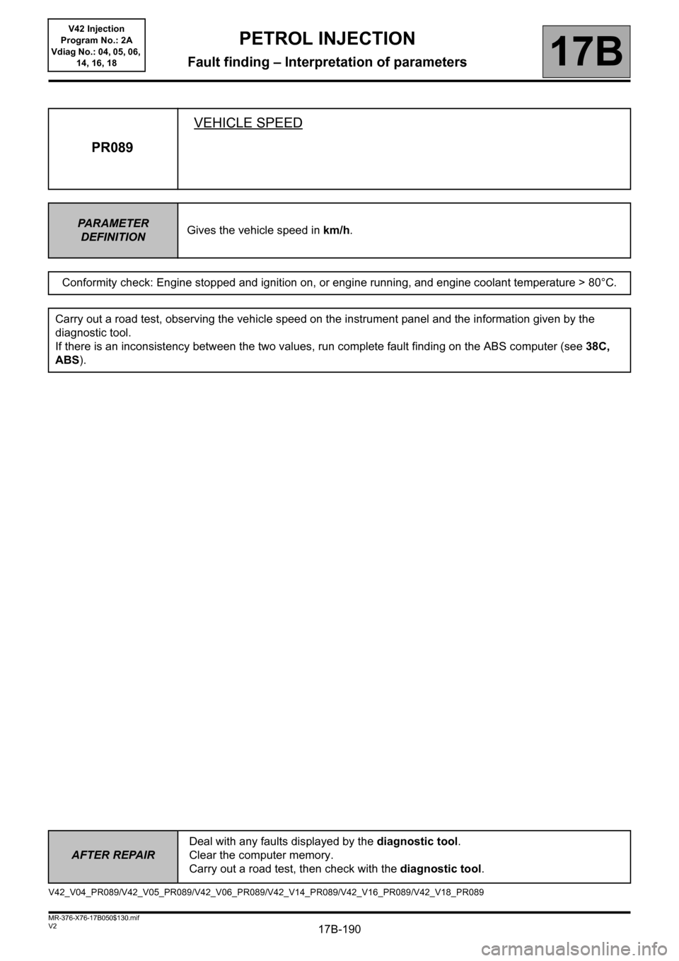
PR089VEHICLE SPEED
PA R A M E T E R
DEFINITIONGives the vehicle speed in km/h.
Conformity check: Engine stopped and ignition on, or engine running, and engine coolant temperature > 80°C.
Carry out a road test, observing the vehicle speed on the instrument panel and the information given by the
diagnostic tool.
If there is an inconsistency between the two values, run complete fault finding on the ABS computer (see 38C,
ABS).
V42_V04_PR089/V42_V05_PR089/V42_V06_PR089/V42_V14_PR089/V42_V16_PR089/V42_V18_PR089
Page 198 of 279
17B-198
AFTER REPAIRCarry out a road test, then check with the diagnostic tool.
V2 MR-376-X76-17B050$130.mif
PETROL INJECTION
Fault finding – Interpretation of parameters17B
V42 Injection
Program No.: 2A
Vdiag No.: 04, 05, 06,
14, 16, 18
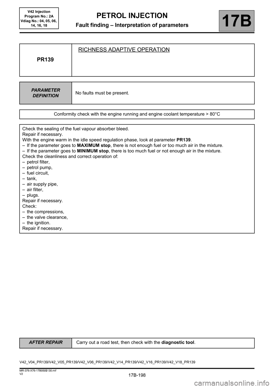
PR139RICHNESS ADAPTIVE OPERATION
PA R A M E T E R
DEFINITIONNo faults must be present.
Conformity check with the engine running and engine coolant temperature > 80°C
Check the sealing of the fuel vapour absorber bleed.
Repair if necessary.
With the engine warm in the idle speed regulation phase, look at parameter PR139.
– If the parameter goes to MAXIMUM stop, there is not enough fuel or too much air in the mixture.
– If the parameter goes to MINIMUM stop, there is too much fuel or not enough air in the mixture.
Check the cleanliness and correct operation of:
– petrol filter,
– petrol pump,
– fuel circuit,
–tank,
– air supply pipe,
– air filter,
– plugs.
Repair if necessary.
Check:
– the compressions,
– the valve clearance,
– the ignition.
Repair if necessary.
V42_V04_PR139/V42_V05_PR139/V42_V06_PR139/V42_V14_PR139/V42_V16_PR139/V42_V18_PR139
Page 206 of 279
17B-206
AFTER REPAIRCarry out a road test, then check with the diagnostic tool.
V2 MR-376-X76-17B050$130.mif
PETROL INJECTION
Fault finding – Interpretation of parameters17B
V42 Injection
Program No.: 2A
Vdiag No.: 04, 05, 06,
14, 16, 18
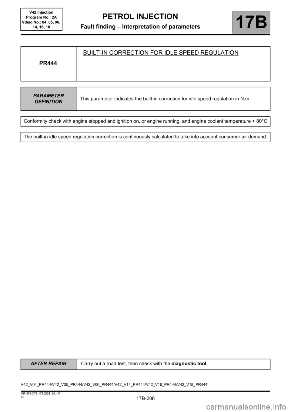
PR444BUILT-IN CORRECTION FOR IDLE SPEED REGULATION
PA R A M E T E R
DEFINITIONThis parameter indicates the built-in correction for idle speed regulation in N.m.
Conformity check with engine stopped and ignition on, or engine running, and engine coolant temperature > 80°C
The built-in idle speed regulation correction is continuously calculated to take into account consumer air demand.
V42_V04_PR444/V42_V05_PR444/V42_V06_PR444/V42_V14_PR444/V42_V16_PR444/V42_V18_PR444
Page 209 of 279
17B-209V2 MR-376-X76-17B050$130.mif
PETROL INJECTION
Fault finding – Interpretation of parameters17B
V42 Injection
Program No.: 2A
Vdiag No.: 04, 05, 06,
14, 16, 18
AFTER REPAIRDeal with any faults displayed by the diagnostic tool.
Clear the computer memory.
Carry out a road test, then check with the diagnostic tool.
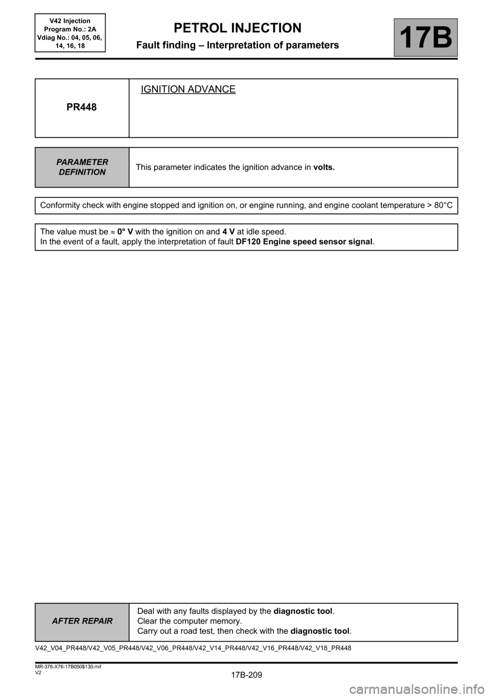
PR448IGNITION ADVANCE
PA R A M E T E R
DEFINITIONThis parameter indicates the ignition advance in volts.
Conformity check with engine stopped and ignition on, or engine running, and engine coolant temperature > 80°C
The value must be 0° V with the ignition on and 4 V at idle speed.
In the event of a fault, apply the interpretation of fault DF120 Engine speed sensor signal.
V42_V04_PR448/V42_V05_PR448/V42_V06_PR448/V42_V14_PR448/V42_V16_PR448/V42_V18_PR448
Page 213 of 279
17B-213V2 MR-376-X76-17B050$140.mif
17B
V42 Injection
Program No.: 2A
Vdiag No.: 04, 05, 06,
14, 16, 18
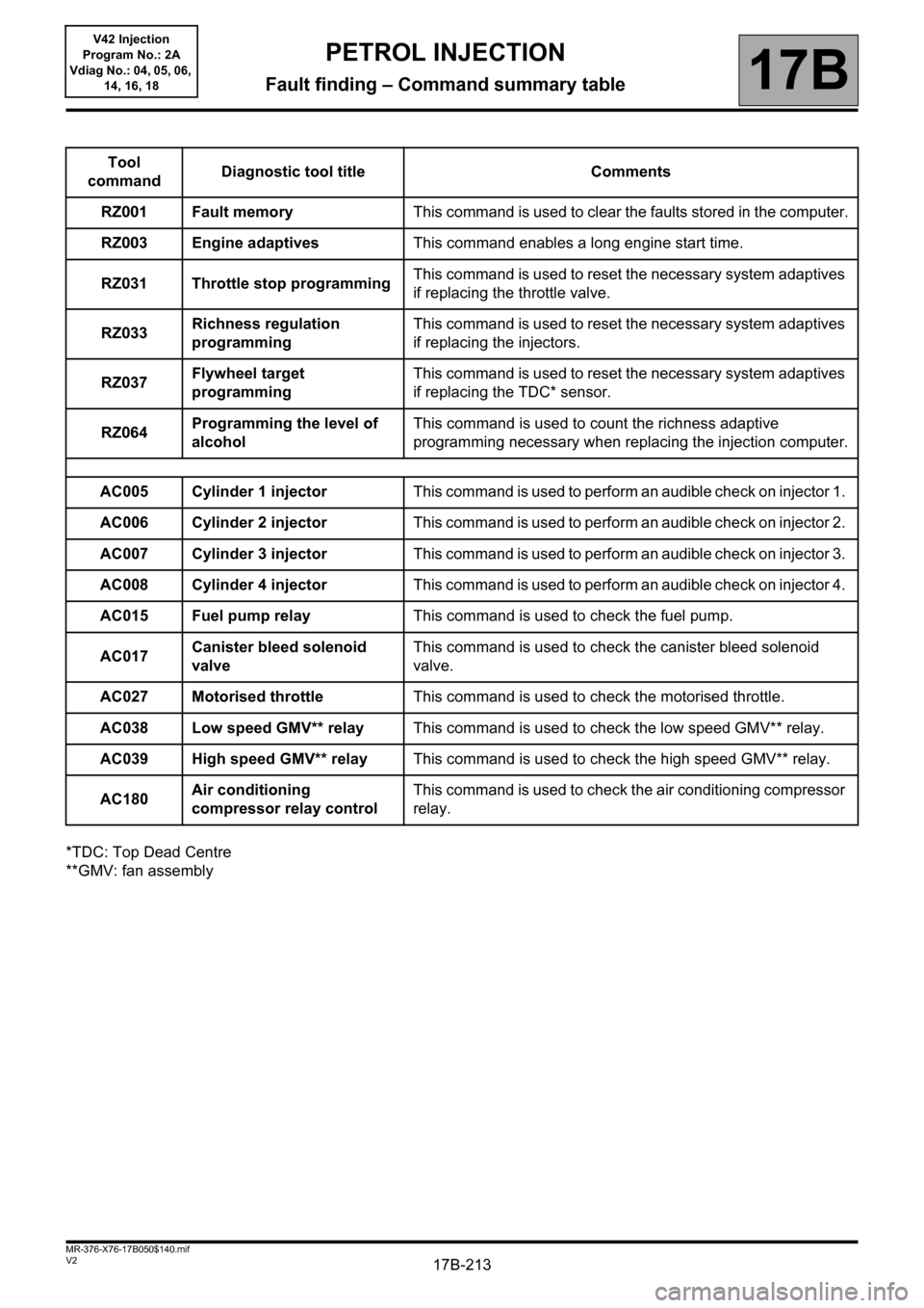
*TDC: Top Dead Centre
**GMV: fan assemblyTool
commandDiagnostic tool title Comments
RZ001 Fault memoryThis command is used to clear the faults stored in the computer.
RZ003 Engine adaptivesThis command enables a long engine start time.
RZ031 Throttle stop programmingThis command is used to reset the necessary system adaptives
if replacing the throttle valve.
RZ033Richness regulation
programmingThis command is used to reset the necessary system adaptives
if replacing the injectors.
RZ037Flywheel target
programmingThis command is used to reset the necessary system adaptives
if replacing the TDC* sensor.
RZ064Programming the level of
alcoholThis command is used to count the richness adaptive
programming necessary when replacing the injection computer.
AC005 Cylinder 1 injectorThis command is used to perform an audible check on injector 1.
AC006 Cylinder 2 injectorThis command is used to perform an audible check on injector 2.
AC007 Cylinder 3 injectorThis command is used to perform an audible check on injector 3.
AC008 Cylinder 4 injectorThis command is used to perform an audible check on injector 4.
AC015 Fuel pump relayThis command is used to check the fuel pump.
AC017Canister bleed solenoid
valveThis command is used to check the canister bleed solenoid
valve.
AC027 Motorised throttleThis command is used to check the motorised throttle.
AC038 Low speed GMV** relayThis command is used to check the low speed GMV** relay.
AC039 High speed GMV** relayThis command is used to check the high speed GMV** relay.
AC180Air conditioning
compressor relay controlThis command is used to check the air conditioning compressor
relay.
PETROL INJECTION
Fault finding – Command summary table
Page 218 of 279
17B-218V2 MR-376-X76-17B050$150.mif
PETROL INJECTION
Fault finding – Customer complaints17B
V42 Injection
Program No.: 2A
Vdiag No.: 04, 05, 06,
14, 16, 18
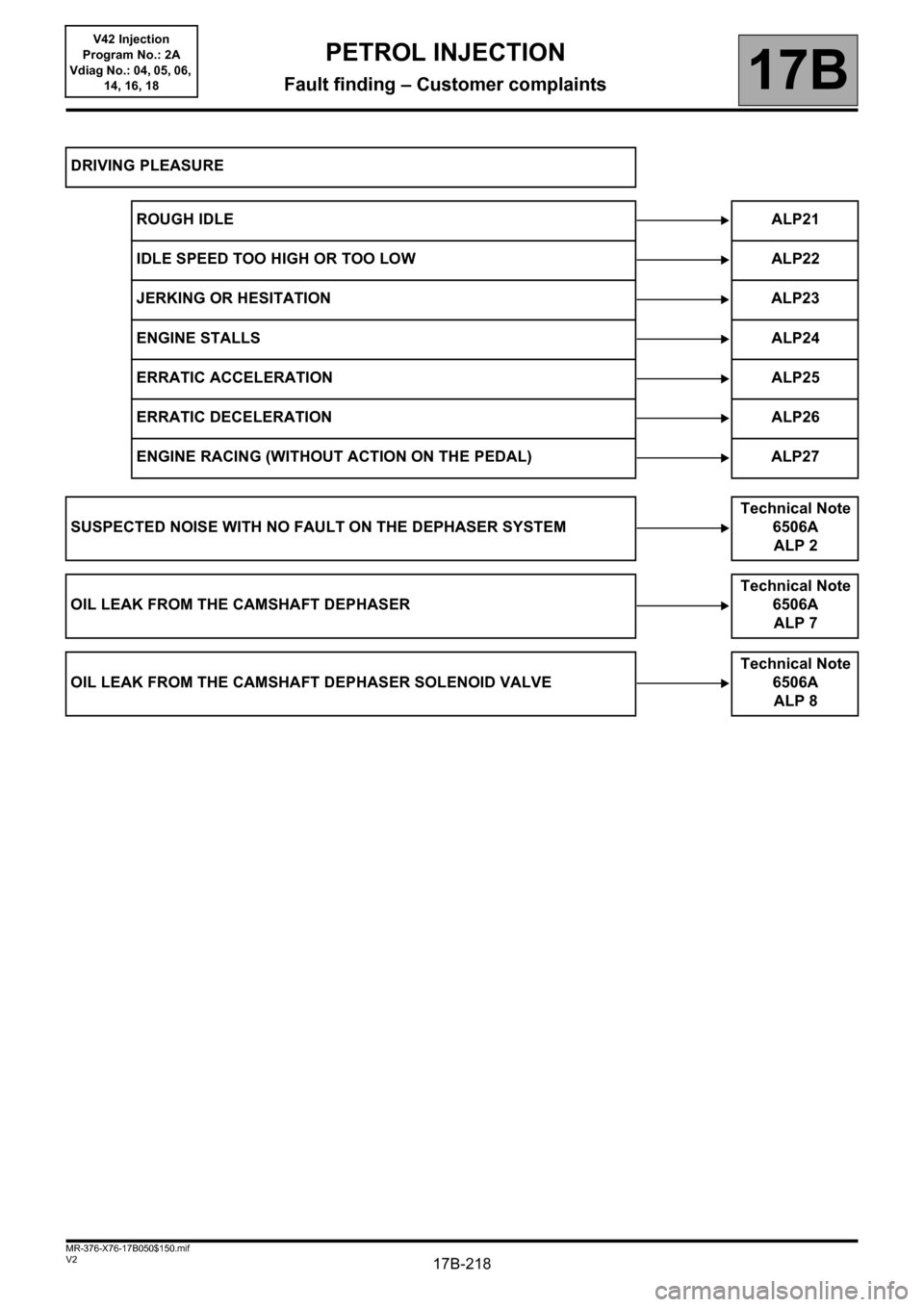
DRIVING PLEASURE
ROUGH IDLEALP21
IDLE SPEED TOO HIGH OR TOO LOW ALP22
JERKING OR HESITATION ALP23
ENGINE STALLSALP24
ERRATIC ACCELERATION ALP25
ERRATIC DECELERATION ALP26
ENGINE RACING (WITHOUT ACTION ON THE PEDAL) ALP27
SUSPECTED NOISE WITH NO FAULT ON THE DEPHASER SYSTEMTechnical Note
6506A
ALP 2
OIL LEAK FROM THE CAMSHAFT DEPHASERTechnical Note
6506A
ALP 7
OIL LEAK FROM THE CAMSHAFT DEPHASER SOLENOID VALVETechnical Note
6506A
ALP 8
Page 242 of 279
17B-242
AFTER REPAIRCarry out a road test, then check with the diagnostic tool.
V2 MR-376-X76-17B050$160.mif
PETROL INJECTION
Fault finding – Fault Finding Chart17B
V42 Injection
Program No.: 2A
Vdiag No.: 04, 05, 06,
14, 16, 18
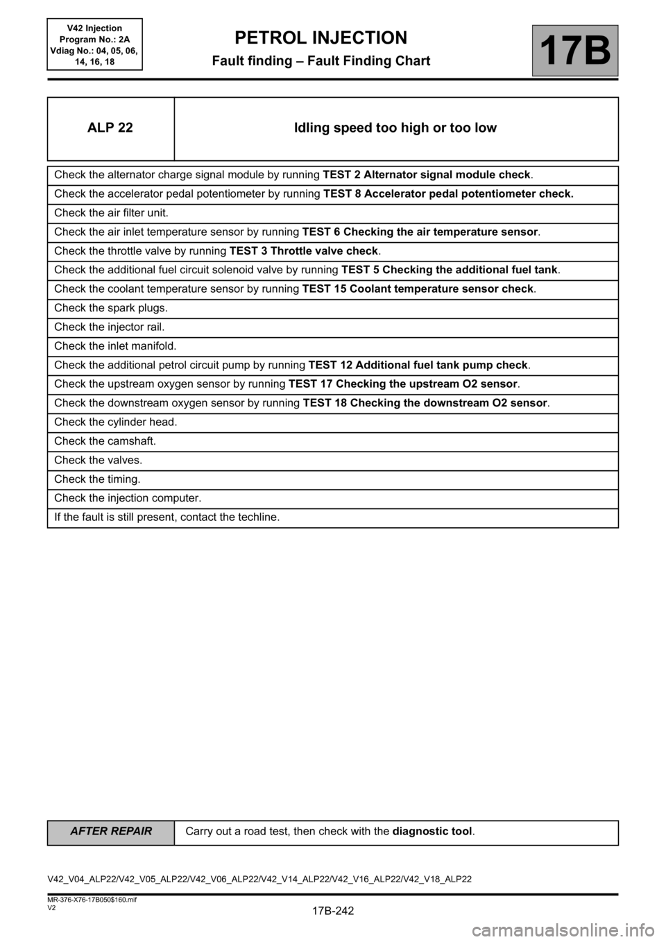
ALP 22 Idling speed too high or too low
Check the alternator charge signal module by running TEST 2 Alternator signal module check.
Check the accelerator pedal potentiometer by running TEST 8 Accelerator pedal potentiometer check.
Check the air filter unit.
Check the air inlet temperature sensor by running TEST 6 Checking the air temperature sensor.
Check the throttle valve by running TEST 3 Throttle valve check.
Check the additional fuel circuit solenoid valve by running TEST 5 Checking the additional fuel tank.
Check the coolant temperature sensor by running TEST 15 Coolant temperature sensor check.
Check the spark plugs.
Check the injector rail.
Check the inlet manifold.
Check the additional petrol circuit pump by running TEST 12 Additional fuel tank pump check.
Check the upstream oxygen sensor by running TEST 17 Checking the upstream O2 sensor.
Check the downstream oxygen sensor by running TEST 18 Checking the downstream O2 sensor.
Check the cylinder head.
Check the camshaft.
Check the valves.
Check the timing.
Check the injection computer.
If the fault is still present, contact the techline.
V42_V04_ALP22/V42_V05_ALP22/V42_V06_ALP22/V42_V14_ALP22/V42_V16_ALP22/V42_V18_ALP22
Page 252 of 279
17B-252
AFTER REPAIRCarry out a road test, then check with the diagnostic tool.
V2 MR-376-X76-17B050$180.mif
PETROL INJECTION
Fault finding – Tests17B
V42 Injection
Program No.: 2A
Vdiag No.: 04, 05, 06,
14, 16, 18
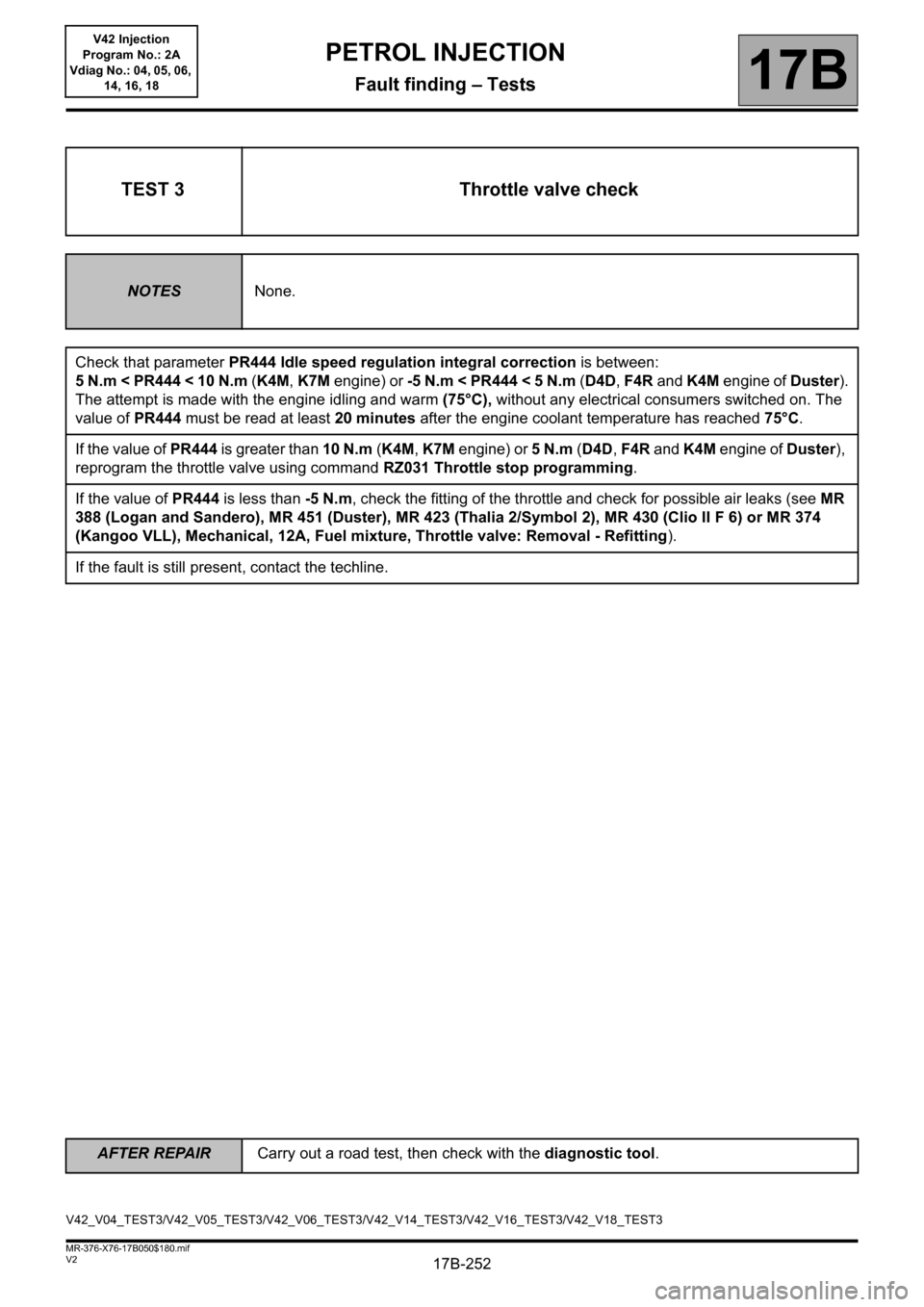
TEST 3 Throttle valve check
NOTESNone.
Check that parameter PR444 Idle speed regulation integral correction is between:
5 N.m < PR444 < 10 N.m (K4M, K7M engine) or -5 N.m < PR444 < 5 N.m (D4D, F4R and K4M engine of Duster).
The attempt is made with the engine idling and warm (75°C), without any electrical consumers switched on. The
value of PR444 must be read at least 20 minutes after the engine coolant temperature has reached 75°C.
If the value of PR444 is greater than 10 N.m (K4M, K7M engine) or 5 N.m (D4D, F4R and K4M engine of Duster),
reprogram the throttle valve using command RZ031 Throttle stop programming.
If the value of PR444 is less than -5 N.m, check the fitting of the throttle and check for possible air leaks (see MR
388 (Logan and Sandero), MR 451 (Duster), MR 423 (Thalia 2/Symbol 2), MR 430 (Clio II F 6) or MR 374
(Kangoo VLL), Mechanical, 12A, Fuel mixture, Throttle valve: Removal - Refitting).
If the fault is still present, contact the techline.
V42_V04_TEST3/V42_V05_TEST3/V42_V06_TEST3/V42_V14_TEST3/V42_V16_TEST3/V42_V18_TEST3
Page 259 of 279
17B-259
AFTER REPAIRCarry out a road test, then check with the diagnostic tool.
V2 MR-376-X76-17B050$180.mif
PETROL INJECTION
Fault finding – Tests17B
V42 Injection
Program No.: 2A
Vdiag No.: 04, 05, 06,
14, 16, 18
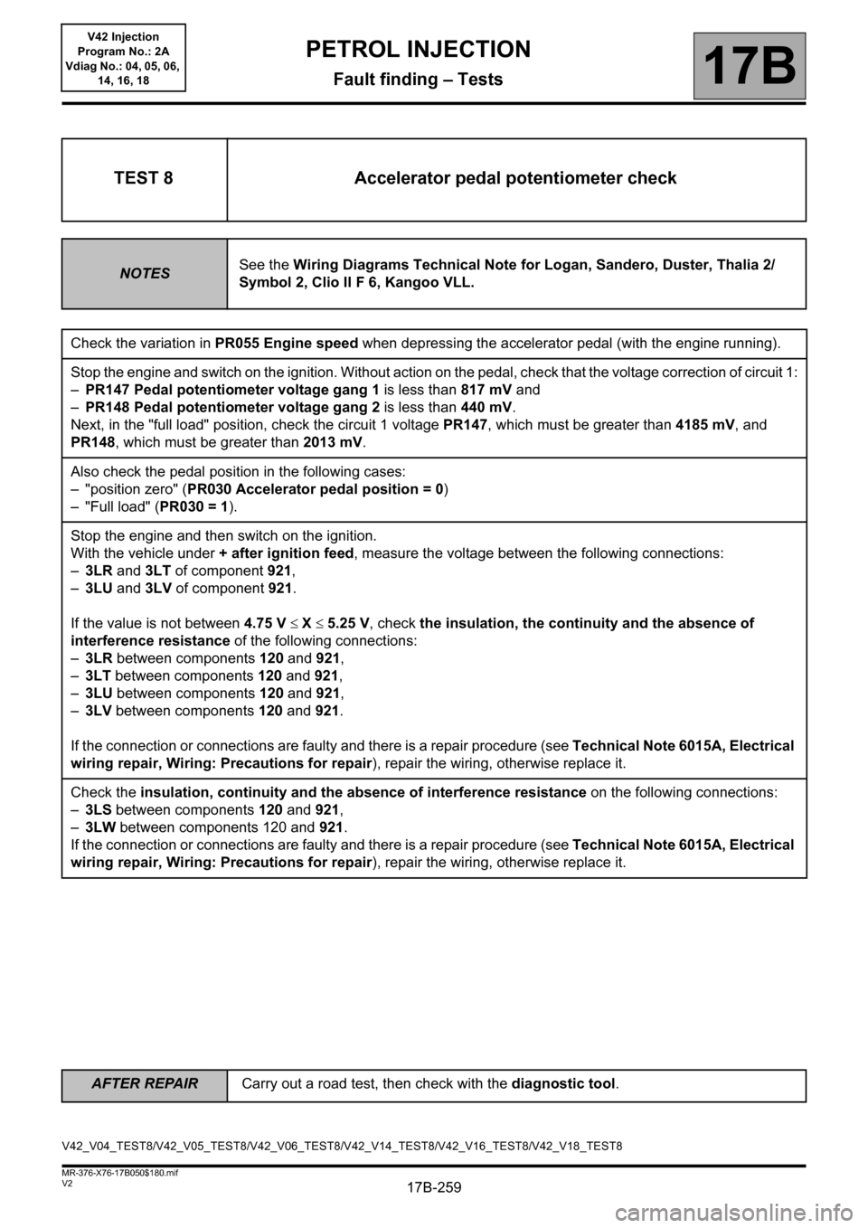
TEST 8 Accelerator pedal potentiometer check
NOTESSee the Wiring Diagrams Technical Note for Logan, Sandero, Duster, Thalia 2/
Symbol 2, Clio II F 6, Kangoo VLL.
Check the variation in PR055 Engine speed when depressing the accelerator pedal (with the engine running).
Stop the engine and switch on the ignition. Without action on the pedal, check that the voltage correction of circuit 1:
–PR147 Pedal potentiometer voltage gang 1 is less than 817 mV and
–PR148 Pedal potentiometer voltage gang 2 is less than 440 mV.
Next, in the "full load" position, check the circuit 1 voltage PR147, which must be greater than 4185 mV, and
PR148, which must be greater than 2013 mV.
Also check the pedal position in the following cases:
– "position zero" (PR030 Accelerator pedal position = 0)
– "Full load" (PR030 = 1).
Stop the engine and then switch on the ignition.
With the vehicle under + after ignition feed, measure the voltage between the following connections:
–3LR and 3LT of component 921,
–3LU and 3LV of component 921.
If the value is not between 4.75 VX5.25 V, check the insulation, the continuity and the absence of
interference resistance of the following connections:
–3LR between components 120 and 921,
–3LT between components 120 and 921,
–3LU between components 120 and 921,
–3LV between components 120 and 921.
If the connection or connections are faulty and there is a repair procedure (see Technical Note 6015A, Electrical
wiring repair, Wiring: Precautions for repair), repair the wiring, otherwise replace it.
Check the insulation, continuity and the absence of interference resistance on the following connections:
–3LS between components 120
and 921,
–3LW between components 120 and 921.
If the connection or connections are faulty and there is a repair procedure (see Technical Note 6015A, Electrical
wiring repair, Wiring: Precautions for repair), repair the wiring, otherwise replace it.
V42_V04_TEST8/V42_V05_TEST8/V42_V06_TEST8/V42_V14_TEST8/V42_V16_TEST8/V42_V18_TEST8
Page 264 of 279
17B-264
AFTER REPAIRCarry out a road test, then check with the diagnostic tool.
V2 MR-376-X76-17B050$180.mif
PETROL INJECTION
Fault finding – Tests17B
V42 Injection
Program No.: 2A
Vdiag No.: 04, 05, 06,
14, 16, 18
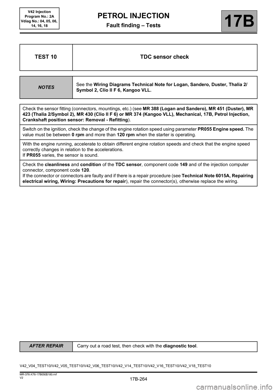
TEST 10 TDC sensor check
NOTESSee the Wiring Diagrams Technical Note for Logan, Sandero, Duster, Thalia 2/
Symbol 2, Clio II F 6, Kangoo VLL.
Check the sensor fitting (connectors, mountings, etc.) (see MR 388 (Logan and Sandero), MR 451 (Duster), MR
423 (Thalia 2/Symbol 2), MR 430 (Clio II F 6) or MR 374 (Kangoo VLL), Mechanical, 17B, Petrol Injection,
Crankshaft position sensor: Removal - Refitting).
Switch on the ignition, check the change of the engine rotation speed using parameter PR055 Engine speed. The
value must be between 0 rpm and more than 120 rpm when the starter is operating.
With the engine running, accelerate to obtain different engine rotation speeds and check that the engine speed
correctly changes in relation to the accelerations.
If PR055 varies, the sensor is sound.
Check the cleanliness and condition of the TDC sensor, component code 149 and of the injection computer
connector, component code 120.
If the connector or connectors are faulty and if there is a repair procedure (see Technical Note 6015A, Repairing
electrical wiring, Wiring: Precautions for repair), repair the connector(s), otherwise replace the wiring.
V42_V04_TEST10/V42_V05_TEST10/V42_V06_TEST10/V42_V14_TEST10/V42_V16_TEST10/V42_V18_TEST10