battery RENAULT KANGOO 2013 X61 / 2.G Petrol V42 Injection Workshop Manual
[x] Cancel search | Manufacturer: RENAULT, Model Year: 2013, Model line: KANGOO, Model: RENAULT KANGOO 2013 X61 / 2.GPages: 279, PDF Size: 1.29 MB
Page 3 of 279
17B-3V2 MR-376-X76-17B050$010.mif
PETROL INJECTION
Fault finding – Introduction17B
V42 Injection
Program No.: 2A
Vdiag No.: 04, 05, 06,
14, 16, 18
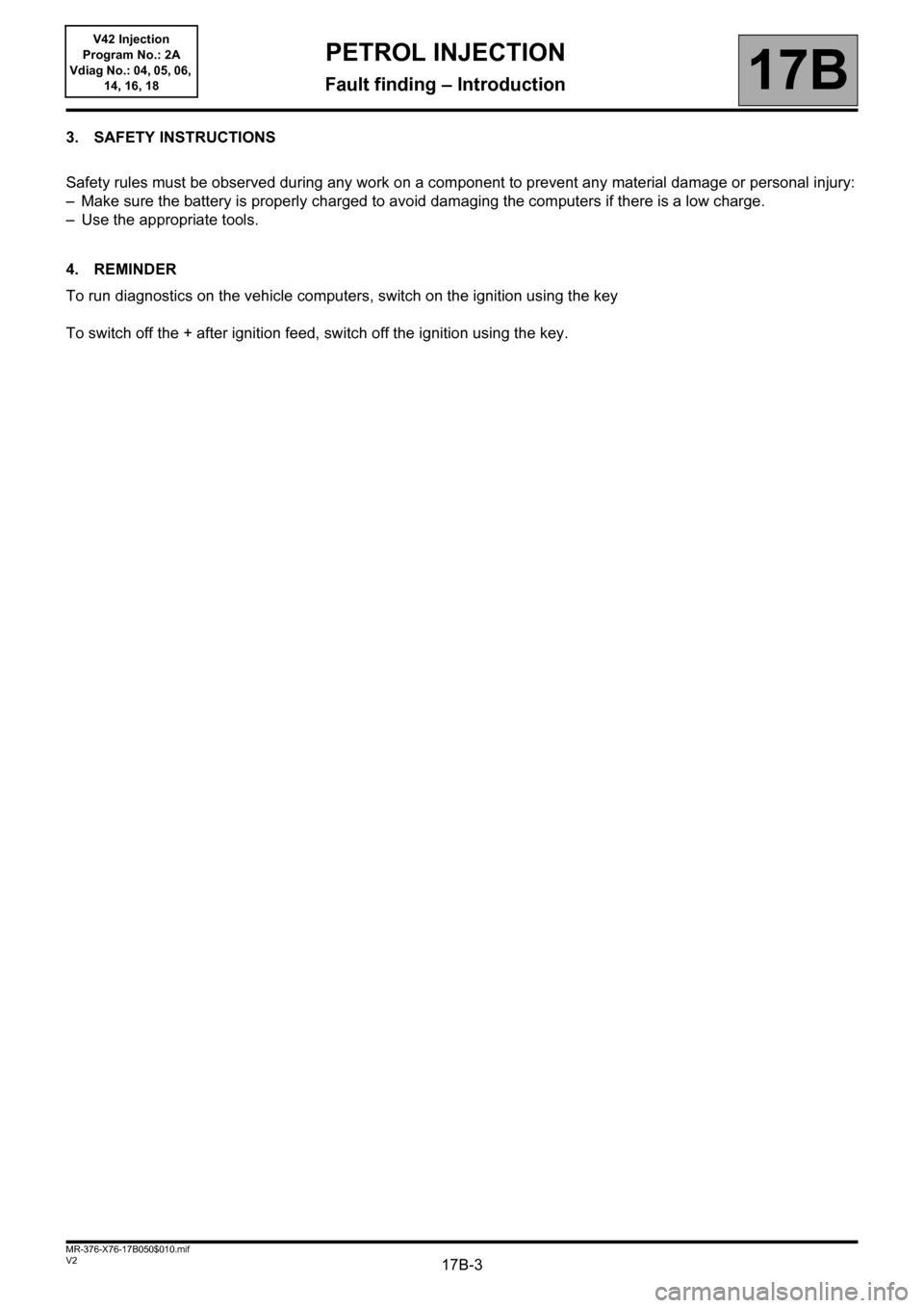
3. SAFETY INSTRUCTIONS
Safety rules must be observed during any work on a component to prevent any material damage or personal injury:
– Make sure the battery is properly charged to avoid damaging the computers if there is a low charge.
– Use the appropriate tools.
4. REMINDER
To run diagnostics on the vehicle computers, switch on the ignition using the key
To switch off the + after ignition feed, switch off the ignition using the key.
Page 4 of 279
17B-4V2 MR-376-X76-17B050$020.mif
17B
V42 Injection
Program No.: 2A
Vdiag No.: 04, 05, 06,
14, 16, 18
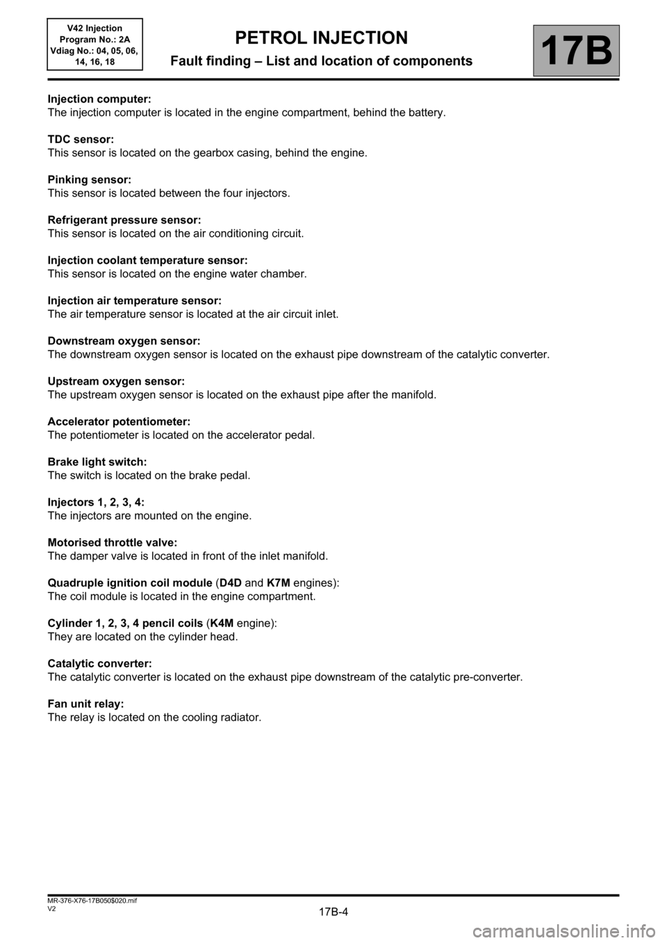
Injection computer:
The injection computer is located in the engine compartment, behind the battery.
TDC sensor:
This sensor is located on the gearbox casing, behind the engine.
Pinking sensor:
This sensor is located between the four injectors.
Refrigerant pressure sensor:
This sensor is located on the air conditioning circuit.
Injection coolant temperature sensor:
This sensor is located on the engine water chamber.
Injection air temperature sensor:
The air temperature sensor is located at the air circuit inlet.
Downstream oxygen sensor:
The downstream oxygen sensor is located on the exhaust pipe downstream of the catalytic converter.
Upstream oxygen sensor:
The upstream oxygen sensor is located on the exhaust pipe after the manifold.
Accelerator potentiometer:
The potentiometer is located on the accelerator pedal.
Brake light switch:
The switch is located on the brake pedal.
Injectors 1, 2, 3, 4:
The injectors are mounted on the engine.
Motorised throttle valve:
The damper valve is located in front of the inlet manifold.
Quadruple ignition coil module (D4D and K7M engines):
The coil module is located in the engine compartment.
Cylinder 1, 2, 3, 4 pencil coils (K4M engine):
They are located on the cylinder head.
Catalytic converter:
The catalytic converter is located on the exhaust pipe downstream of the catalytic pre-converter.
Fan unit relay:
The relay is located on the cooling radiator.
PETROL INJECTION
Fault finding – List and location of components
Page 12 of 279
17B-12V2 MR-376-X76-17B050$060.mif
17B
V42 Injection
Program No.: 2A
Vdiag No.: 04, 05, 06,
14, 16, 18
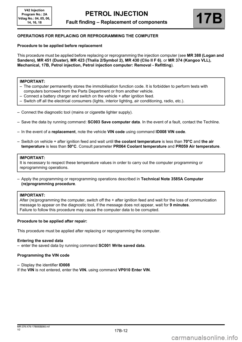
OPERATIONS FOR REPLACING OR REPROGRAMMING THE COMPUTER
Procedure to be applied before replacement
This procedure must be applied before replacing or reprogramming the injection computer (see MR 388 (Logan and
Sandero), MR 451 (Duster), MR 423 (Thalia 2/Symbol 2), MR 430 (Clio II F 6), or MR 374 (Kangoo VLL),
Mechanical, 17B, Petrol injection, Petrol injection computer: Removal - Refitting).
– Connect the diagnostic tool (mains or cigarette lighter supply).
– Save the data by running command: SC003 Save computer data. In the event of a fault, contact the Techline.
– In the event of a replacement, note the vehicle VIN code using command ID008 VIN code.
– Switch on vehicle + after ignition feed and wait until the coolant temperature is less than 70°C and the air
temperature is less than 50°C. Consult parameter PR064 Coolant temperature and PR059 Air temperature.
– Apply the programming or reprogramming operations described in Technical Note 3585A Computer
(re)programming procedure.
Procedure to be applied after repair:
This procedure must be applied after replacing or reprogramming the computer.
Entering the saved data
– enter the saved data by running command SC001 Write saved data.
Programming the VIN code
– Display the identifier ID008
If the VIN is not entered, enter the VIN. using command VP010 Enter VIN. IMPORTANT:
– The computer permanently stores the immobilisation function code. It is forbidden to perform tests with
computers borrowed from the Parts Department or from another vehicle.
– Connect a battery charger and switch on the vehicle + after ignition feed.
– Switch off all the electrical consumers (lights, interior lighting, air conditioning, radio, etc.).
IMPORTANT:
It is necessary to respect these temperature values in order to carry out the computer programming or
reprogramming operations.
IMPORTANT:
After (re)programming the computer, switch off the + after ignition feed and wait for the loss of communication
message to appear on the diagnostic tool, if the message does not appear, wait for 9 minutes.
Failure to follow this procedure may cause the computer data to be corrupted.
PETROL INJECTION
Fault finding – Replacement of components
Page 16 of 279
17B-16V2 MR-376-X76-17B050$070.mif
17B
V42 Injection
Program No.: 2A
Vdiag No.: 04, 05, 06,
14, 16, 18
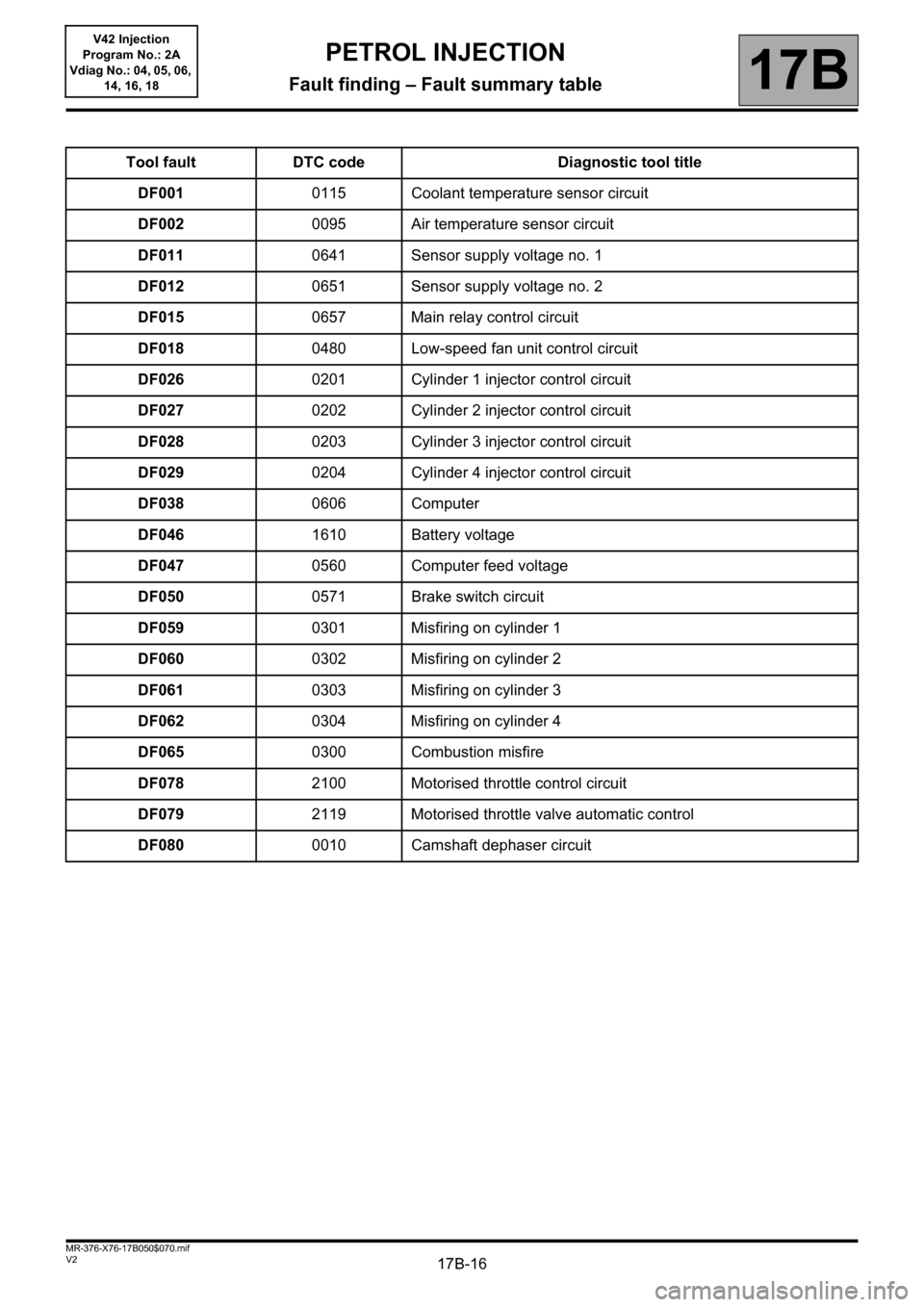
Tool fault DTC code Diagnostic tool title
DF0010115 Coolant temperature sensor circuit
DF0020095 Air temperature sensor circuit
DF0110641 Sensor supply voltage no. 1
DF0120651 Sensor supply voltage no. 2
DF0150657 Main relay control circuit
DF0180480 Low-speed fan unit control circuit
DF0260201 Cylinder 1 injector control circuit
DF0270202 Cylinder 2 injector control circuit
DF0280203 Cylinder 3 injector control circuit
DF0290204 Cylinder 4 injector control circuit
DF0380606 Computer
DF0461610 Battery voltage
DF0470560 Computer feed voltage
DF0500571 Brake switch circuit
DF0590301 Misfiring on cylinder 1
DF0600302 Misfiring on cylinder 2
DF0610303 Misfiring on cylinder 3
DF0620304 Misfiring on cylinder 4
DF0650300 Combustion misfire
DF0782100 Motorised throttle control circuit
DF0792119 Motorised throttle valve automatic control
DF0800010 Camshaft dephaser circuit
PETROL INJECTION
Fault finding – Fault summary table
Page 37 of 279
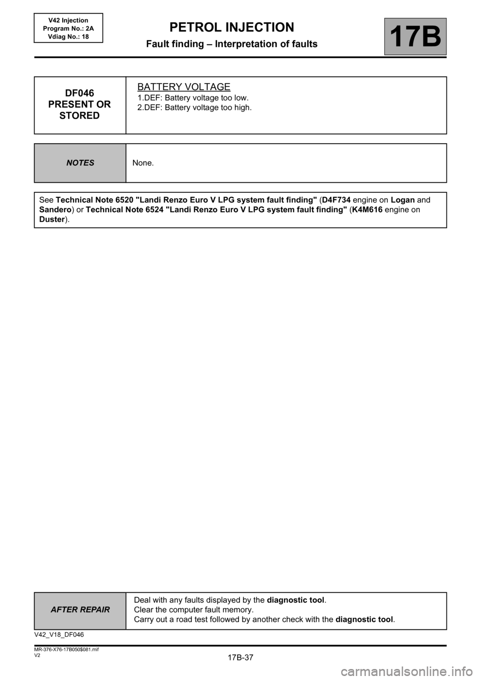
17B-37
AFTER REPAIRDeal with any faults displayed by the diagnostic tool.
Clear the computer fault memory.
Carry out a road test followed by another check with the diagnostic tool.
V2 MR-376-X76-17B050$081.mif
PETROL INJECTION
Fault finding – Interpretation of faults17B
V42 Injection
Program No.: 2A
Vdiag No.: 18
DF046
PRESENT OR
STOREDBATTERY VOLTAGE1.DEF: Battery voltage too low.
2.DEF: Battery voltage too high.
NOTESNone.
See Technical Note 6520 "Landi Renzo Euro V LPG system fault finding" (D4F734 engine on Logan and
Sandero) or Technical Note 6524 "Landi Renzo Euro V LPG system fault finding" (K4M616 engine on
Duster).
V42_V18_DF046
Page 38 of 279
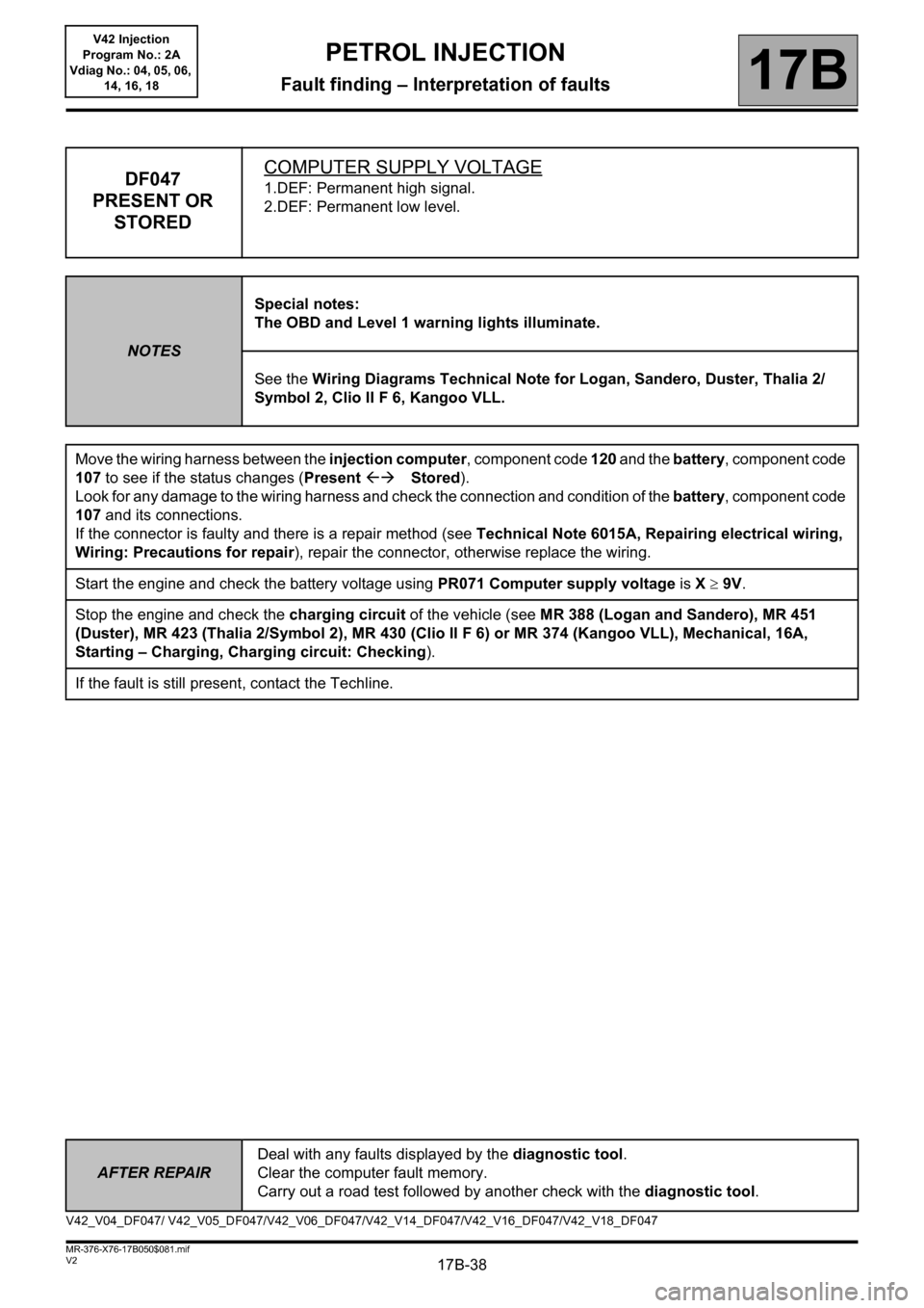
17B-38
AFTER REPAIRDeal with any faults displayed by the diagnostic tool.
Clear the computer fault memory.
Carry out a road test followed by another check with the diagnostic tool.
V2 MR-376-X76-17B050$081.mif
PETROL INJECTION
Fault finding – Interpretation of faults17B
V42 Injection
Program No.: 2A
Vdiag No.: 04, 05, 06,
14, 16, 18
DF047
PRESENT OR
STOREDCOMPUTER SUPPLY VOLTAGE1.DEF: Permanent high signal.
2.DEF: Permanent low level.
NOTESSpecial notes:
The OBD and Level 1 warning lights illuminate.
See the Wiring Diagrams Technical Note for Logan, Sandero, Duster, Thalia 2/
Symbol 2, Clio II F 6, Kangoo VLL.
Move the wiring harness between the injection computer, component code 120 and the battery, component code
107 to see if the status changes (Present Stored).
Look for any damage to the wiring harness and check the connection and condition of the battery, component code
107 and its connections.
If the connector is faulty and there is a repair method (see Technical Note 6015A, Repairing electrical wiring,
Wiring: Precautions for repair), repair the connector, otherwise replace the wiring.
Start the engine and check the battery voltage using PR071 Computer supply voltage is X 9V.
Stop the engine and check the charging circuit of the vehicle (see MR 388 (Logan and Sandero), MR 451
(Duster), MR 423 (Thalia 2/Symbol 2), MR 430 (Clio II F 6) or MR 374 (Kangoo VLL), Mechanical, 16A,
Starting – Charging, Charging circuit: Checking).
If the fault is still present, contact the Techline.
V42_V04_DF047/ V42_V05_DF047/V42_V06_DF047/V42_V14_DF047/V42_V16_DF047/V42_V18_DF047
Page 52 of 279
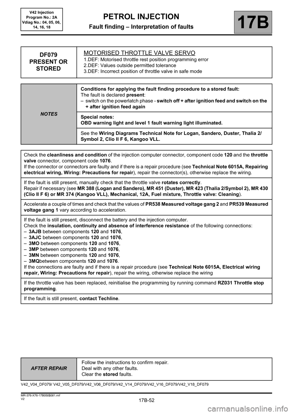
17B-52V2 MR-376-X76-17B050$081.mif
PETROL INJECTION
Fault finding – Interpretation of faults17B
V42 Injection
Program No.: 2A
Vdiag No.: 04, 05, 06,
14, 16, 18
AFTER REPAIRFollow the instructions to confirm repair.
Deal with any other faults.
Clear the stored faults.
DF079
PRESENT OR
STOREDMOTORISED THROTTLE VALVE SERVO1.DEF: Motorised throttle rest position programming error
2.DEF: Values outside permitted tolerance
3.DEF: Incorrect position of throttle valve in safe mode
NOTESConditions for applying the fault finding procedure to a stored fault:
The fault is declared present:
– switch on the powerlatch phase - switch off + after ignition feed and switch on the
+ after ignition feed again
Special notes:
OBD warning light and level 1 fault warning light illuminated.
See the Wiring Diagrams Technical Note for Logan, Sandero, Duster, Thalia 2/
Symbol 2, Clio II F 6, Kangoo VLL.
Check the cleanliness and condition of the injection computer connector, component code 120 and the throttle
valve connector, component code 1076.
If the connector or connectors are faulty and if there is a repair procedure (see Technical Note 6015A, Repairing
electrical wiring, Wiring: Precautions for repair), repair the connector(s), otherwise replace the wiring.
If the fault is still present, manually check that the throttle valve rotates correctly.
Repair if necessary (see MR 388 (Logan and Sandero), MR 451 (Duster), MR 423 (Thalia 2/Symbol 2), MR 430
(Clio II F 6) or MR 374 (Kangoo VLL), Mechanical, 12A, Fuel mixture, Throttle valve: Cleaning).
Accelerate a couple of times and check that the values of PR538 Measured voltage gang 2 and PR539 Measured
voltage gang 1 vary according to acceleration.
If the fault is still present, disconnect the battery and the injection computer.
Check the insulation, continuity and absence of interference resistance of the following connections:
–3AJB between components 120 and 1076,
–3AJC between components 120 and 1076,
–3MO between components 120 and 1076,
–3MP between components 120 and 1076,
–3MN between components 120 and 1076,
–3MQbetween components 120 and 1076.
If the connections are faulty and if there is a repair procedure (see Technical Note 6015A, Electrical wiring
repair, Wiring: Precautions for repair), repair the wiring, otherwise replace the wiring
If the throttle valve has been replaced, reinitialise the programming by running command RZ031 Throttle stop
programming.
If the fault is still present, contact Techline.
V42_V04_DF079/ V42_V05_DF079/V42_V06_DF079/V42_V14_DF079/V42_V16_DF079/V42_V18_DF079
Page 129 of 279
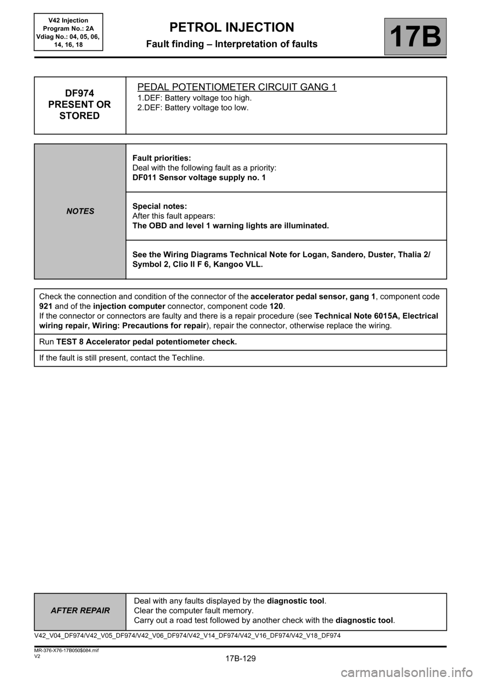
17B-129
AFTER REPAIRDeal with any faults displayed by the diagnostic tool.
Clear the computer fault memory.
Carry out a road test followed by another check with the diagnostic tool.
V2 MR-376-X76-17B050$084.mif
PETROL INJECTION
Fault finding – Interpretation of faults17B
V42 Injection
Program No.: 2A
Vdiag No.: 04, 05, 06,
14, 16, 18
DF974
PRESENT OR
STOREDPEDAL POTENTIOMETER CIRCUIT GANG 11.DEF: Battery voltage too high.
2.DEF: Battery voltage too low.
NOTESFault priorities:
Deal with the following fault as a priority:
DF011 Sensor voltage supply no. 1
Special notes:
After this fault appears:
The OBD and level 1 warning lights are illuminated.
See the Wiring Diagrams Technical Note for Logan, Sandero, Duster, Thalia 2/
Symbol 2, Clio II F 6, Kangoo VLL.
Check the connection and condition of the connector of the accelerator pedal sensor, gang 1, component code
921 and of the injection computer connector, component code 120.
If the connector or connectors are faulty and there is a repair procedure (see Technical Note 6015A, Electrical
wiring repair, Wiring: Precautions for repair), repair the connector, otherwise replace the wiring.
Run TEST 8 Accelerator pedal potentiometer check.
If the fault is still present, contact the Techline.
V42_V04_DF974/V42_V05_DF974/V42_V06_DF974/V42_V14_DF974/V42_V16_DF974/V42_V18_DF974
Page 130 of 279
17B-130
AFTER REPAIRDeal with any faults displayed by the diagnostic tool.
Clear the computer fault memory.
Carry out a road test followed by another check with the diagnostic tool.
V2 MR-376-X76-17B050$084.mif
PETROL INJECTION
Fault finding – Interpretation of faults17B
V42 Injection
Program No.: 2A
Vdiag No.: 04, 05, 06,
14, 16, 18
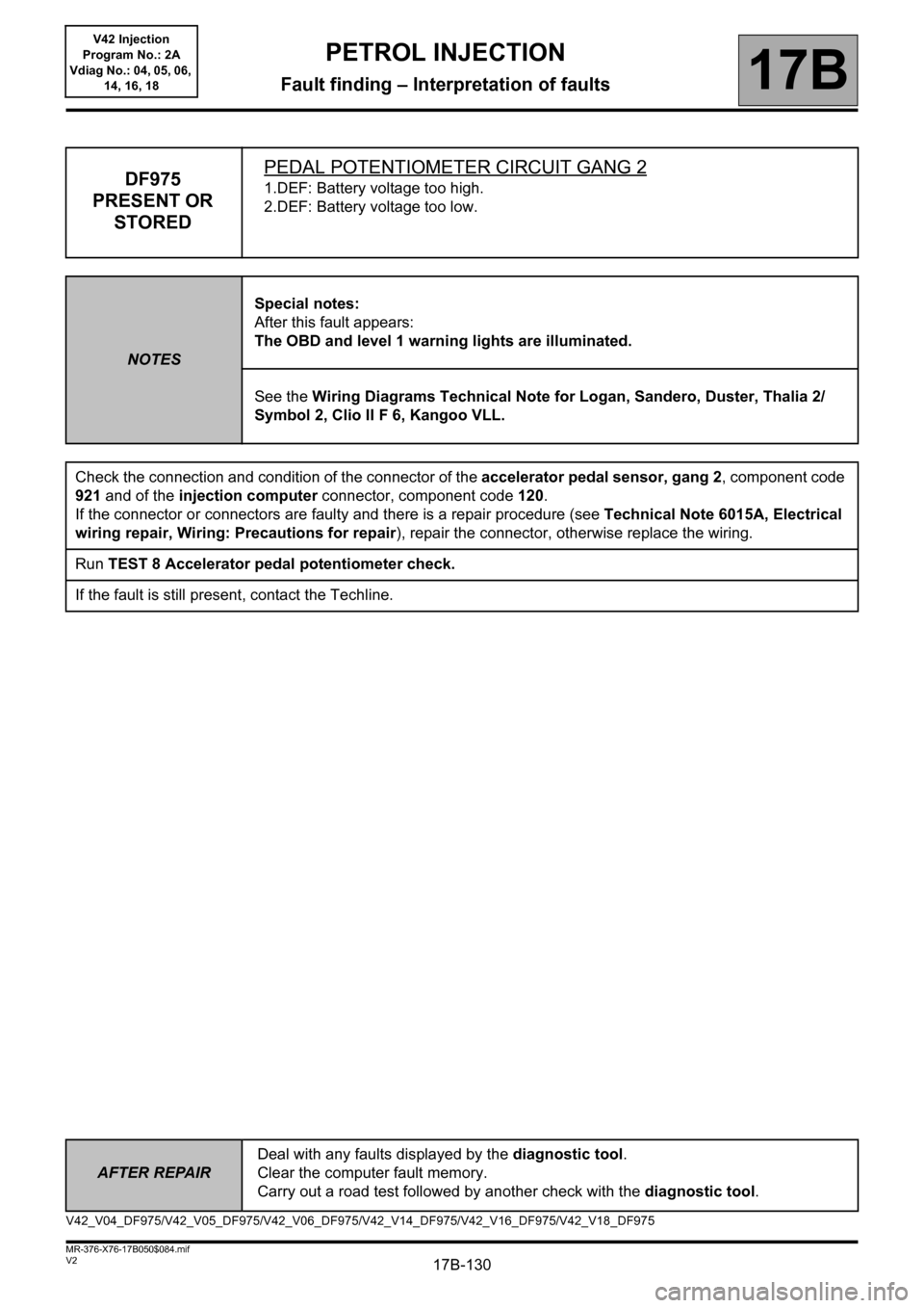
DF975
PRESENT OR
STOREDPEDAL POTENTIOMETER CIRCUIT GANG 21.DEF: Battery voltage too high.
2.DEF: Battery voltage too low.
NOTESSpecial notes:
After this fault appears:
The OBD and level 1 warning lights are illuminated.
See the Wiring Diagrams Technical Note for Logan, Sandero, Duster, Thalia 2/
Symbol 2, Clio II F 6, Kangoo VLL.
Check the connection and condition of the connector of the accelerator pedal sensor, gang 2, component code
921 and of the injection computer connector, component code 120.
If the connector or connectors are faulty and there is a repair procedure (see Technical Note 6015A, Electrical
wiring repair, Wiring: Precautions for repair), repair the connector, otherwise replace the wiring.
Run TEST 8 Accelerator pedal potentiometer check.
If the fault is still present, contact the Techline.
V42_V04_DF975/V42_V05_DF975/V42_V06_DF975/V42_V14_DF975/V42_V16_DF975/V42_V18_DF975
Page 184 of 279
17B-184
AFTER REPAIRCarry out a road test, then check with the diagnostic tool.
V2 MR-376-X76-17B050$130.mif
PETROL INJECTION
Fault finding – Interpretation of parameters17B
V42 Injection
Program No.: 2A
Vdiag No.: 04, 05, 06,
14, 16, 18
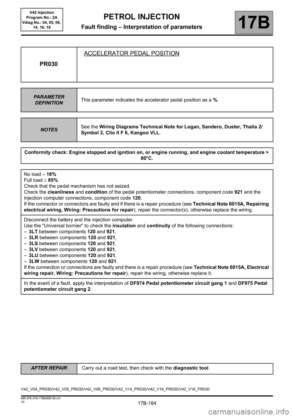
PR030ACCELERATOR PEDAL POSITION
PA R A M E T E R
DEFINITIONThis parameter indicates the accelerator pedal position as a %.
NOTESSee the Wiring Diagrams Technical Note for Logan, Sandero, Duster, Thalia 2/
Symbol 2, Clio II F 6, Kangoo VLL.
Conformity check: Engine stopped and ignition on, or engine running, and engine coolant temperature >
80°C.
No load 16%
Full load 85%
Check that the pedal mechanism has not seized.
Check the cleanliness and condition of the pedal potentiometer connections, component code 921 and the
injection computer connections, component code 120.
If the connector or connectors are faulty and if there is a repair procedure (see Technical Note 6015A, Repairing
electrical wiring, Wiring: Precautions for repair), repair the connector(s), otherwise replace the wiring.
Disconnect the battery and the injection computer.
Use the "Universal bornier" to check the insulation and continuity of the following connections:
–3LT between components 120 and 921,
–3LR between components 120 and 921,
–3LS between components 120 and 921,
–3LV between components 120 and 921,
–3LU between components 120 and 921,
–3LW between components 120 and 921.
If the connection or connections are faulty and there is a repair procedure (see Technical Note 6015A, Electrical
wiring repair, Wiring: Precautions for repair), repair the wiring, otherwise replace it.
In the event of a fault, apply the interpretation of DF974 Pedal potentiometer circuit gang 1 and DF975 Pedal
potentiometer circuit gang 2.
V42_V04_PR030/V42_V05_PR030/V42_V06_PR030/V42_V14_PR030/V42_V16_PR030/V42_V18_PR030