RENAULT KANGOO VAN ZERO EMISSION 2012 X61 / 2.G Manual Online
Manufacturer: RENAULT, Model Year: 2012, Model line: KANGOO VAN ZERO EMISSION, Model: RENAULT KANGOO VAN ZERO EMISSION 2012 X61 / 2.GPages: 220, PDF Size: 4.52 MB
Page 81 of 220
1.75
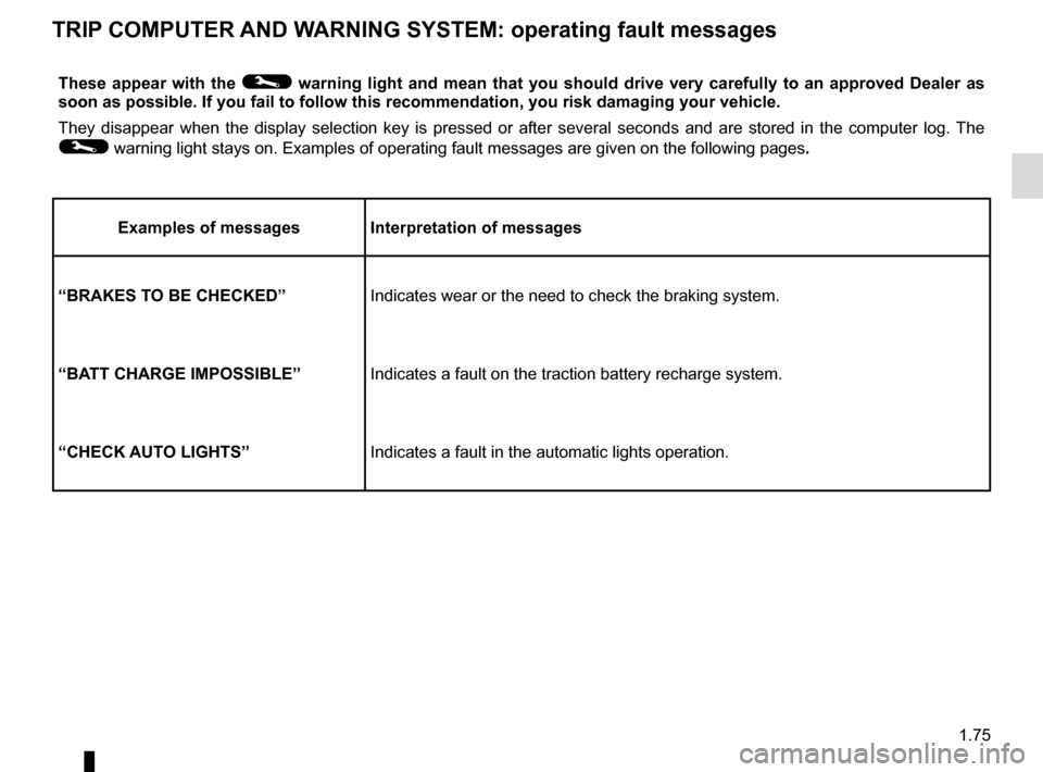
These appear with the © warning light and mean that you should drive very carefully to an approv\
ed Dealer as
soon as possible. If you fail to follow this recommendation, you risk da\
maging your vehicle.
They disappear when the display selection key is pressed or after severa\
l seconds and are stored in the computer log. The
© warning light stays on. Examples of operating fault messages are given \
on the following pages .
Examples of messages Interpretation of messages
“BRAKES TO BE CHECKED” Indicates wear or the need to check the braking system.
“BATT CHARGE IMPOSSIBLE” Indicates a fault on the traction battery recharge system.
“CHECK AUTO LIGHTS” Indicates a fault in the automatic lights operation.
TRIP COMPUTER AND WARNING SYSTEM: operating fault messages
Page 82 of 220
1.76
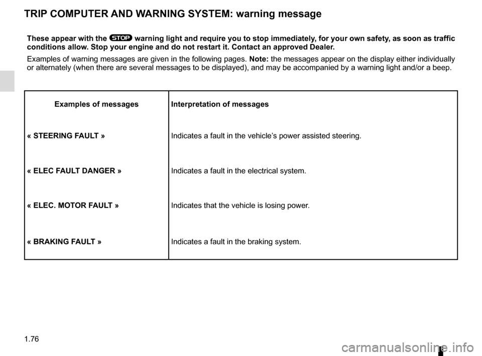
These appear with the ® warning light and require you to stop immediately, for your own safety, as soon as traffic
conditions allow. Stop your engine and do not restart it. Contact an approved Dealer.
Examples of warning messages are given in the following pages. Note: the messages appear on the display either individually
or alternately (when there are several messages to be displayed), and \
may be accompanied by a warning light and/or a beep.
Examples of messages Interpretation of messages
« STEERING FAULT » Indicates a fault in the vehicle’s power assisted steering.
« ELEC FAULT DANGER » Indicates a fault in the electrical system.
« ELEC. MOTOR FAULT » Indicates that the vehicle is losing power.
« BRAKING FAULT » Indicates a fault in the braking system.
TRIP COMPUTER AND WARNING SYSTEM: warning message
Page 83 of 220
1.77
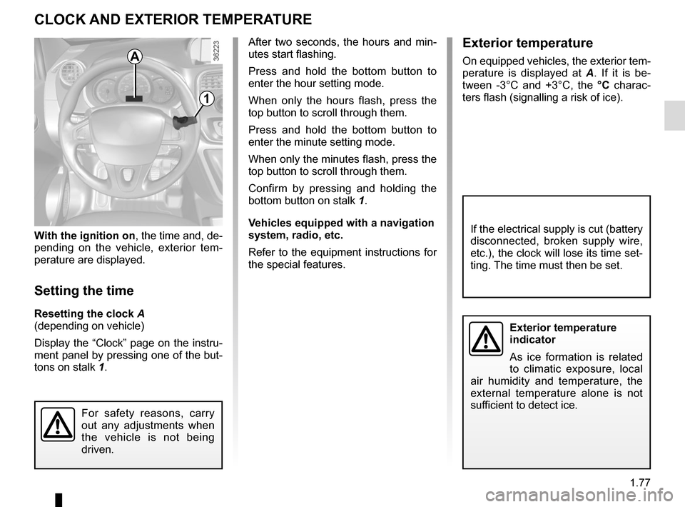
With the ignition on, the time and, de-
pending on the vehicle, exterior tem-
perature are displayed.
Setting the time
Resetting the clock A
(depending on vehicle)
Display the “Clock” page on the instru-
ment panel by pressing one of the but-
tons on stalk 1.
CLOCK AND EXTERIOR TEMPERATURE
Exterior temperature
indicator
As ice formation is related
to climatic exposure, local
air humidity and temperature, the
external temperature alone is not
sufficient to detect ice.
If the electrical supply is cut (battery
disconnected, broken supply wire,
etc.), the clock will lose its time set-
ting. The time must then be set.
A
1
For safety reasons, carry
out any adjustments when
the vehicle is not being
driven.
After two seconds, the hours and min-
utes start flashing.
Press and hold the bottom button to
enter the hour setting mode.
When only the hours flash, press the
top button to scroll through them.
Press and hold the bottom button to
enter the minute setting mode.
When only the minutes flash, press the
top button to scroll through them.
Confirm by pressing and holding the
bottom button on stalk 1.
Vehicles equipped with a navigation
system, radio, etc.
Refer to the equipment instructions for
the special features.Exterior temperature
On equipped vehicles, the exterior tem-
perature is displayed at A. If it is be-
tween -3°C and +3°C, the °C charac-
ters flash (signalling a risk of ice).
Page 84 of 220
1.78
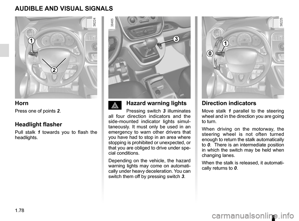
éHazard warning lights
Pressing switch 3 illuminates
all four direction indicators and the
side-mounted indicator lights simul-
taneously. It must only be used in an
emergency to warn other drivers that
you have had to stop in an area where
stopping is prohibited or unexpected, or
that you are obliged to drive under spe-
cial conditions.
Depending on the vehicle, the hazard
warning lights may come on automati-
cally under heavy deceleration. You can
switch them off by pressing switch 3.
Direction indicators
Move stalk 1 parallel to the steering
wheel and in the direction you are going
to turn.
When driving on the motorway, the
steering wheel is not often turned
enough to return the stalk automatically
to 0. There is an intermediate position
in which the switch may be held when
changing lanes.
When the stalk is released, it automati-
cally returns to 0.
Horn
Press one of points 2.
Headlight flasher
Pull stalk 1 towards you to flash the
headlights.
AUDIBLE AND VISUAL SIGNALS
2
31
0
1
Page 85 of 220
1.79
PEDESTRIAN HORN
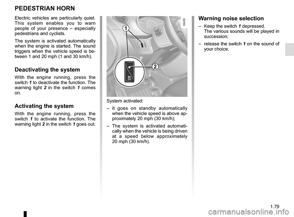
Electric vehicles are particularly quiet.
This system enables you to warn
people of your presence – especially
pedestrians and cyclists.
The system is activated automatically
when the engine is started. The sound
triggers when the vehicle speed is be-
tween 1 and 20 mph (1 and 30 km/h).
Deactivating the system
With the engine running, press the
switch 1 to deactivate the function. The
warning light 2 in the switch 1 comes
on.
Activating the system
With the engine running, press the
switch 1 to activate the function. The
warning light 2 in the switch 1 goes out.
System activated:
– it goes on standby automatically
when the vehicle speed is above ap-
proximately 20 mph (30 km/h);
– The system is activated automati- cally when the vehicle is being driven
at a speed below approximately
20 mph (30 km/h).
Warning noise selection
– Keep the switch 1 depressed.The various sounds will be played in
succession;
– release the switch 1 on the sound of
your choice.
2
1
Page 86 of 220
1.80
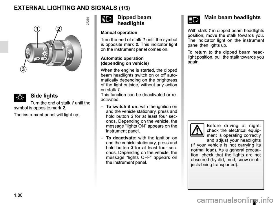
áMain beam headlights
With stalk 1 in dipped beam headlights
position, move the stalk towards you.
The indicator light on the instrument
panel then lights up.
To return to the dipped beam head-
light position, pull the stalk towards you
again.
uSide lights
Turn the end of stalk 1 until the
symbol is opposite mark 2.
The instrument panel will light up.
EXTERNAL LIGHTING AND SIGNALS (1/3)
Before driving at night:
check the electrical equip-
ment is operating correctly
and adjust your headlights
(if your vehicle is not carrying its
normal load). As a general precau-
tion, check that the lights are not
obscured (by dirt, mud, snow or ob-
jects being transported).
kDipped beam
headlights
Manual operation
Turn the end of stalk 1 until the symbol
is opposite mark 2 . This indicator light
on the instrument panel comes on.
Automatic operation
(depending on vehicle)
When the engine is started, the dipped
beam headlights switch on or off auto-
matically depending on the brightness
of the light outside, without any action
on stalk 1.
This function can be deactivated or re-
activated.
– To switch it on: with the ignition on
and the vehicle stationary, press and
hold button 3 for at least four sec-
onds. Depending on the vehicle, the
message “lights ON” appears on the
instrument panel.
– To deactivate: with the ignition on
and the vehicle stationary, press and
hold button 3 for at least four sec-
onds. Depending on the vehicle, the
message “lights OFF” appears on
the instrument panel.12
3
Page 87 of 220
1.81
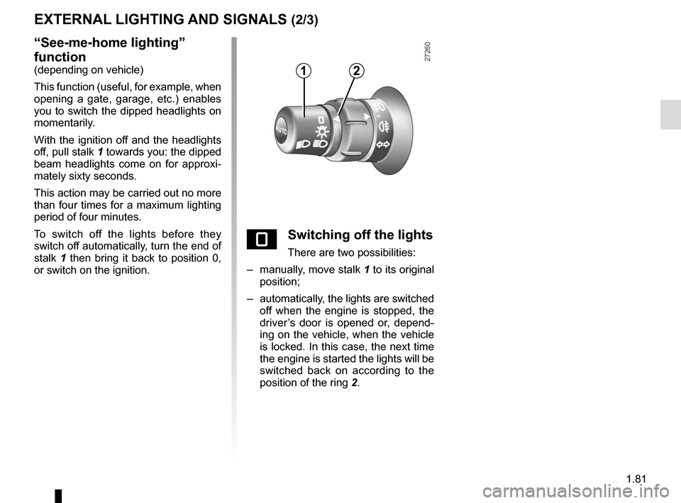
“See-me-home lighting”
function
(depending on vehicle)
This function (useful, for example, when
opening a gate, garage, etc.) enables
you to switch the dipped headlights on
momentarily.
With the ignition off and the headlights
off, pull stalk 1 towards you: the dipped
beam headlights come on for approxi-
mately sixty seconds.
This action may be carried out no more
than four times for a maximum lighting
period of four minutes.
To switch off the lights before they
switch off automatically, turn the end of
stalk 1 then bring it back to position 0,
or switch on the ignition.
EXTERNAL LIGHTING AND SIGNALS (2/3)
eSwitching off the lights
There are two possibilities:
– manually, move stalk 1 to its original
position;
– automatically, the lights are switched off when the engine is stopped, the
driver’s door is opened or, depend-
ing on the vehicle, when the vehicle
is locked. In this case, the next time
the engine is started the lights will be
switched back on according to the
position of the ring 2.
12
Page 88 of 220
1.82
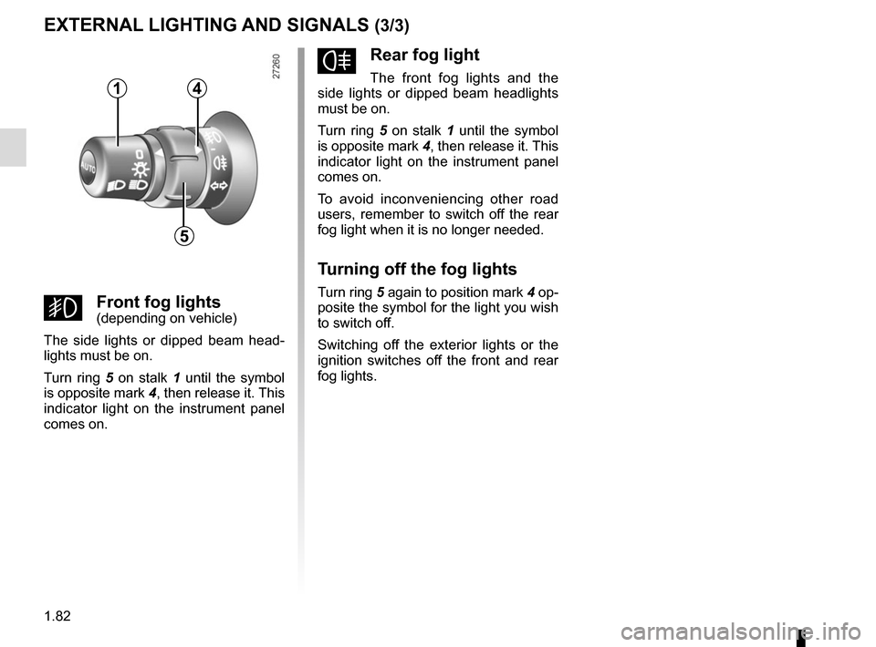
fRear fog light
The front fog lights and the
side lights or dipped beam headlights
must be on.
Turn ring 5 on stalk 1 until the symbol
is opposite mark 4, then release it. This
indicator light on the instrument panel
comes on.
To avoid inconveniencing other road
users, remember to switch off the rear
fog light when it is no longer needed.
Turning off the fog lights
Turn ring 5 again to position mark 4 op-
posite the symbol for the light you wish
to switch off.
Switching off the exterior lights or the
ignition switches off the front and rear
fog lights.
gFront fog lights(depending on vehicle)
The side lights or dipped beam head-
lights must be on.
Turn ring 5 on stalk 1 until the symbol
is opposite mark 4, then release it. This
indicator light on the instrument panel
comes on.
EXTERNAL LIGHTING AND SIGNALS (3/3)
1
5
4
Page 89 of 220
1.83
HEADLIGHT BEAM ADJUSTMENT (1/2)
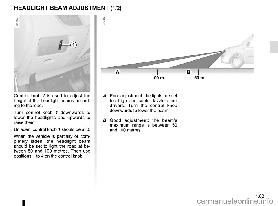
Control knob 1 is used to adjust the
height of the headlight beams accord-
ing to the load.
Turn control knob 1 downwards to
lower the headlights and upwards to
raise them.
Unladen, control knob 1 should be at 0.
When the vehicle is partially or com-
pletely laden, the headlight beam
should be set to light the road at be-
tween 50 and 100 metres. Then use
positions 1 to 4 on the control knob.
AB
100 m 50 m
A Poor adjustment: the lights are set
too high and could dazzle other
drivers. Turn the control knob
downwards to lower the beam.
B Good adjustment: the beam’s
maximum range is between 50
and 100 metres.
1
Page 90 of 220
1.84
HEADLIGHT BEAM ADJUSTMENT (2/2)
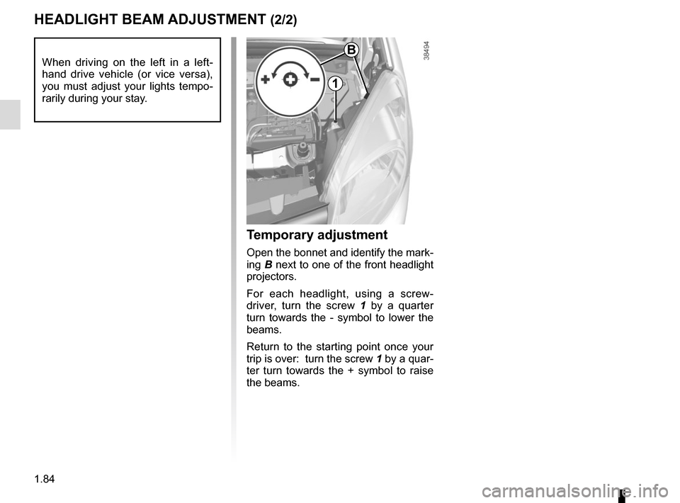
Temporary adjustment
Open the bonnet and identify the mark-
ing B next to one of the front headlight
projectors.
For each headlight, using a screw-
driver, turn the screw 1 by a quarter
turn towards the - symbol to lower the
beams.
Return to the starting point once your
trip is over: turn the screw 1 by a quar-
ter turn towards the + symbol to raise
the beams.
When driving on the left in a left-
hand drive vehicle (or vice versa),
you must adjust your lights tempo-
rarily during your stay.B
1