charging RENAULT SCENIC 2000 J64 / 1.G Technical Note 3426A Workshop Manual
[x] Cancel search | Manufacturer: RENAULT, Model Year: 2000, Model line: SCENIC, Model: RENAULT SCENIC 2000 J64 / 1.GPages: 118, PDF Size: 1.5 MB
Page 2 of 118
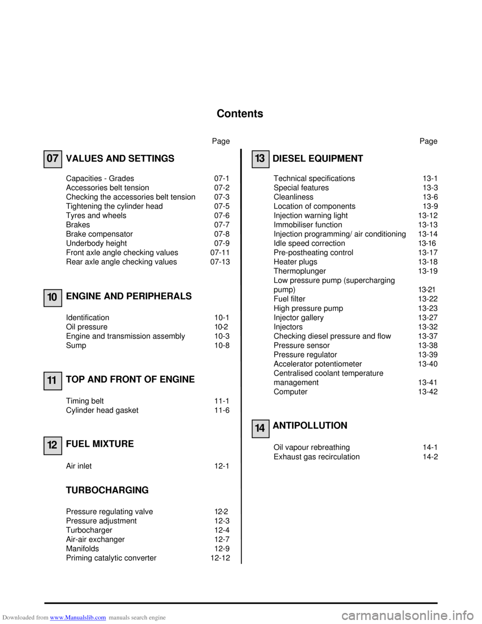
Downloaded from www.Manualslib.com manuals search engine Contents
Page
07
10
11
12
VALUES AND SETTINGS
Capacities - Grades 07-1
Accessories belt tension 07-2
Checking the accessories belt tension 07-3
Tightening the cylinder head 07-5
Tyres and wheels 07-6
Brakes 07-7
Brake compensator 07-8
Underbody height 07-9
Front axle angle checking values 07-11
Rear axle angle checking values 07-13
ENGINE AND PERIPHERALS
Identification 10-1
Oil pressure 10-2
Engine and transmission assembly 10-3
Sump 10-8
TOP AND FRONT OF ENGINE
Timing belt 11-1
Cylinder head gasket 11-6
FUEL MIXTURE
Air inlet 12-1
TURBOCHARGING
Pressure regulating valve 12-2
Pressure adjustment 12-3
Turbocharger 12-4
Air-air exchanger 12-7
Manifolds 12-9
Priming catalytic converter 12-12Page
13
14
DIESEL EQUIPMENT
Technical specifications 13-1
Special features 13-3
Cleanliness 13-6
Location of components 13-9
Injection warning light 13-12
Immobiliser function 13-13
Injection programming/ air conditioning 13-14
Idle speed correction13-16
Pre-postheating control 13-17
Heater plugs 13-18
Thermoplunger 13-19
Low pressure pump (supercharging
pump)13-21
Fuel filter 13-22
High pressure pump 13-23
Injector gallery 13-27
Injectors 13-32
Checking diesel pressure and flow 13-37
Pressure sensor 13-38
Pressure regulator 13-39
Accelerator potentiometer 13-40
Centralised coolant temperature
management 13-41
Computer 13-42
ANTIPOLLUTION
Oil vapour rebreathing 14-1
Exhaust gas recirculation 14-2
Page 3 of 118
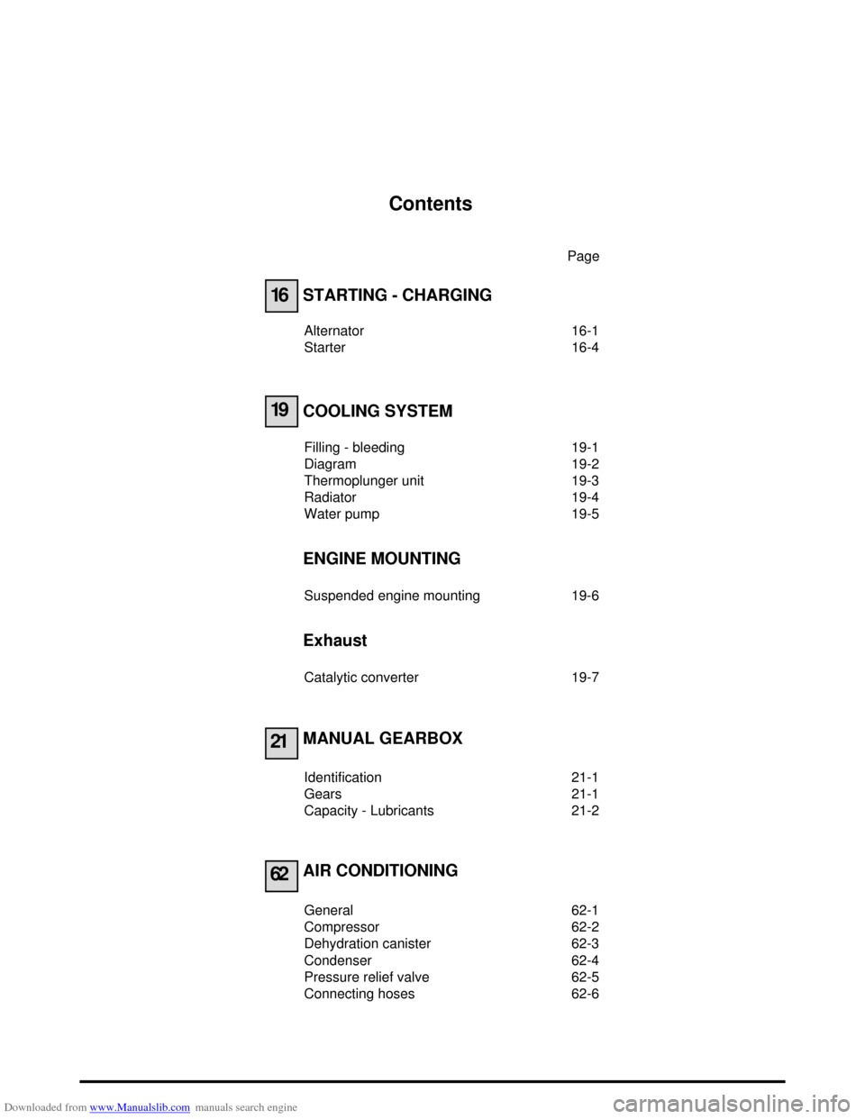
Downloaded from www.Manualslib.com manuals search engine Contents
Page
16
19
21
62
STARTING - CHARGING
Alternator 16-1
Starter 16-4
COOLING SYSTEM
Filling - bleeding 19-1
Diagram 19-2
Thermoplunger unit 19-3
Radiator 19-4
Water pump 19-5
ENGINE MOUNTING
Suspended engine mounting 19-6
Exhaust
Catalytic converter 19-7
MANUAL GEARBOX
Identification 21-1
Gears 21-1
Capacity - Lubricants 21-2
AIR CONDITIONING
General 62-1
Compressor 62-2
Dehydration canister 62-3
Condenser 62-4
Pressure relief valve 62-5
Connecting hoses 62-6
Page 21 of 118
Downloaded from www.Manualslib.com manuals search engine ENGINE AND PERIPHERALS
Engine and transmission assembly
10
10-5
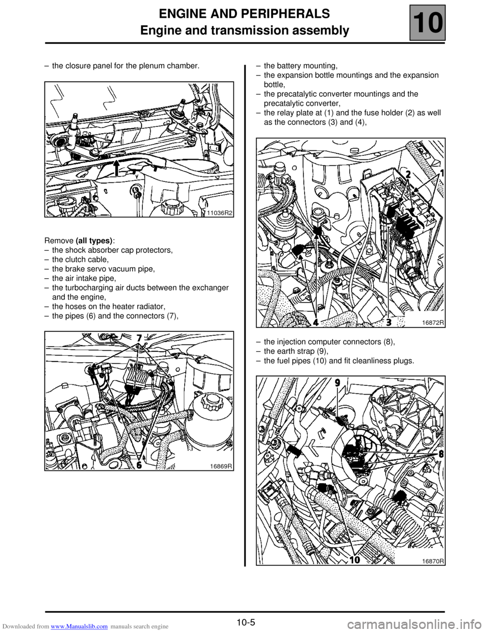
– the closure panel for the plenum chamber.
Remove (all types):
– the shock absorber cap protectors,
– the clutch cable,
– the brake servo vacuum pipe,
– the air intake pipe,
– the turbocharging air ducts between the exchanger
and the engine,
– the hoses on the heater radiator,
– the pipes (6) and the connectors (7),– the battery mounting,
– the expansion bottle mountings and the expansion
bottle,
– the precatalytic converter mountings and the
precatalytic converter,
– the relay plate at (1) and the fuse holder (2) as well
as the connectors (3) and (4),
– the injection computer connectors (8),
– the earth strap (9),
– the fuel pipes (10) and fit cleanliness plugs.
11036R2
16869R
16872R
16870R
Page 40 of 118
Downloaded from www.Manualslib.com manuals search engine TURBOCHARGING
Pressure regulating valve
12
12-2
TURBOCHARGING
Pressure regulating valve
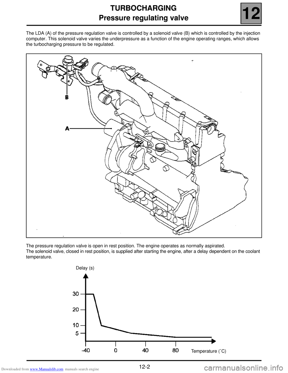
The LDA (A) of the pressure regulation valve is controlled by a solenoid valve (B) which is controlled by the injection
computer. This solenoid valve varies the underpressure as a function of the engine operating ranges, which allows
the turbocharging pressure to be regulated.
The pressure regulation valve is open in rest position. The engine operates as normally aspirated.
The solenoid valve, closed in rest position, is supplied after starting the engine, after a delay dependent on the coolant
temperature.
Delay (s)
Temperature (˚C)
Page 41 of 118
Downloaded from www.Manualslib.com manuals search engine TURBOCHARGING
Pressure adjustment
12
12-3
Pressure adjustment
TURBOCHARGING PRESSURE LIMITATION
VALVE (WASTEGATE)
NB: the limitation valve operates in the opposite
way to the usual fittings.
The absence of control pressure causes a
turbocharging pressure limitation.
Check that there are no leaks between the vacuum
pump and the limitation valve.
Checking calibration pressure
Fit on vehicle.
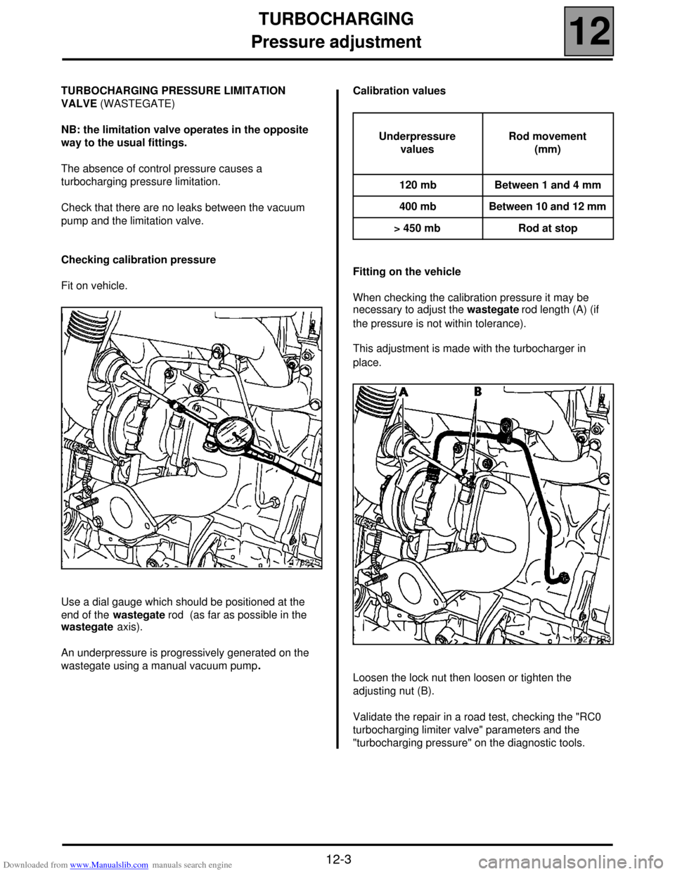
Use a dial gauge which should be positioned at the
end of the wastegate rod (as far as possible in the
wastegate axis).
An underpressure is progressively generated on the
wastegate using a manual vacuum pump.Calibration values
Fitting on the vehicle
When checking the calibration pressure it may be
necessary to adjust the wastegate rod length (A) (if
the pressure is not within tolerance).
This adjustment is made with the turbocharger in
place.
Loosen the lock nut then loosen or tighten the
adjusting nut (B).
Validate the repair in a road test, checking the "RC0
turbocharging limiter valve" parameters and the
"turbocharging pressure" on the diagnostic tools.
17827S
Underpressure
valuesRod movement
(mm)
120 mb Between 1 and 4 mm
400 mb Between 10 and 12 mm
> 450 mb Rod at stop
17827-1R3
Page 42 of 118
Downloaded from www.Manualslib.com manuals search engine TURBOCHARGING
Turbocharger
12
12-4
Turbocharger
SPECIAL TOOLING REQUIRED
Elé. 1294 -01 Tool for removing windscreen
wiper arms
REMOVAL
NOTE: to slacken the turbocharger mounting nuts
more easily on the exhaust manifold, it is useful to
spray a releasing agent on the nuts when still hot, just
before removal.
Disconnect the battery.
Remove the engine cover.
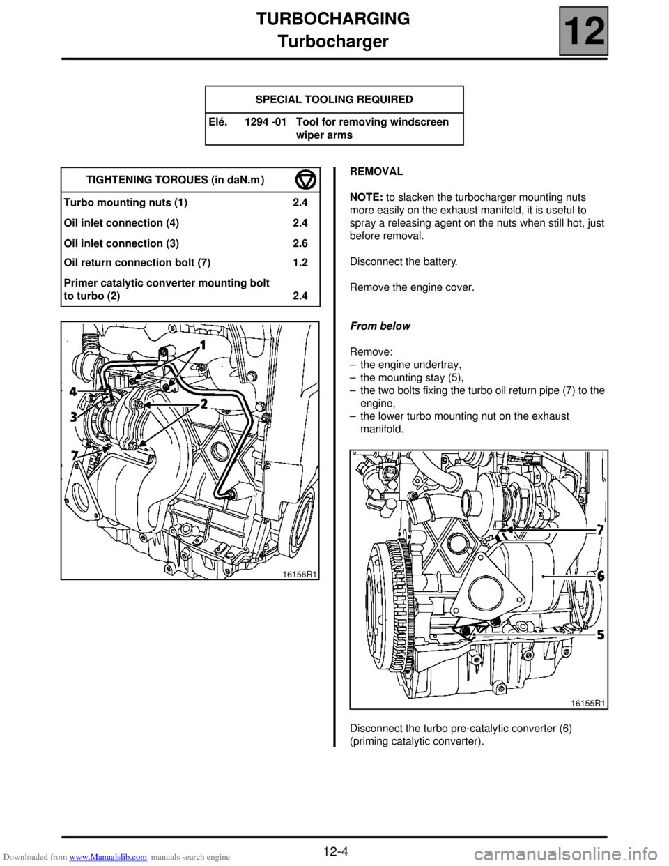
From below
Remove:
– the engine undertray,
– the mounting stay (5),
– the two bolts fixing the turbo oil return pipe (7) to the
engine,
– the lower turbo mounting nut on the exhaust
manifold.
Disconnect the turbo pre-catalytic converter (6)
(priming catalytic converter). TIGHTENING TORQUES (in daN.m )
Turbo mounting nuts (1) 2.4
Oil inlet connection (4) 2.4
Oil inlet connection (3) 2.6
Oil return connection bolt (7) 1.2
Primer catalytic converter mounting bolt
to turbo (2) 2.4
16156R1
16155R1
Page 43 of 118
Downloaded from www.Manualslib.com manuals search engine TURBOCHARGING
Turbocharger
12
12-5
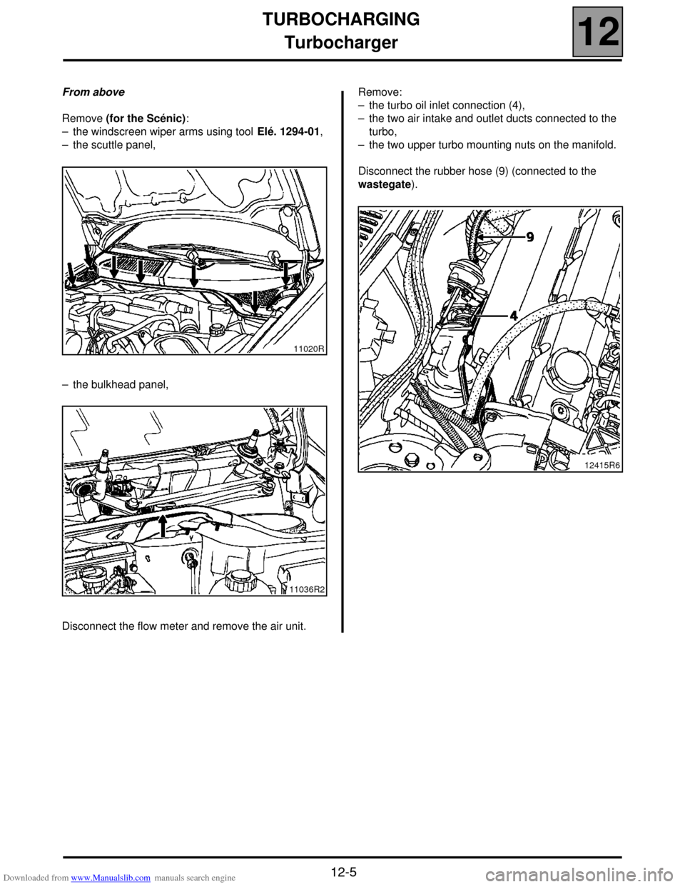
From above
Remove (for the Scénic):
– the windscreen wiper arms using tool Elé. 1294-01,
– the scuttle panel,
– the bulkhead panel,
Disconnect the flow meter and remove the air unit.Remove:
– the turbo oil inlet connection (4),
– the two air intake and outlet ducts connected to the
turbo,
– the two upper turbo mounting nuts on the manifold.
Disconnect the rubber hose (9) (connected to the
wastegate).
11020R
11036R2
12415R6
Page 44 of 118
Downloaded from www.Manualslib.com manuals search engine TURBOCHARGING
Turbocharger
12
12-6
REFITTING
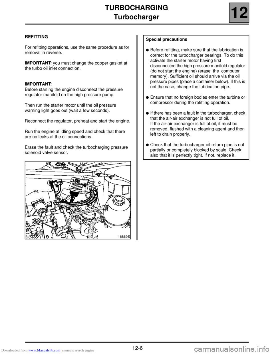
For refitting operations, use the same procedure as for
removal in reverse.
IMPORTANT: you must change the copper gasket at
the turbo oil inlet connection.
IMPORTANT:
Before starting the engine disconnect the pressure
regulator manifold on the high pressure pump.
Then run the starter motor until the oil pressure
warning light goes out (wait a few seconds).
Reconnect the regulator, preheat and start the engine.
Run the engine at idling speed and check that there
are no leaks at the oil connections.
Erase the fault and check the turbocharging pressure
solenoid valve sensor.
16869S
Special precautions
!Before refitting, make sure that the lubrication is
correct for the turbocharger bearings. To do this
activate the starter motor having first
disconnected the high pressure manifold regulator
(do not start the engine) (erase the computer
memory). Sufficient oil should arrive via the oil
pressure pipes (place a container below). If this is
not the case, change the lubrication pipe.
!Ensure that no foreign bodies enter the turbine or
compressor during the refitting operation.
!If there has been a fault in the turbocharger, check
that the air-air exchanger is not full of oil.
If the air-air exchanger is full of oil, it must be
removed, flushed with a cleaning agent and then
left to drain properly.
!Check that the turbocharger oil return pipe is not
partially or completely blocked by scale. Check
also that it is perfectly tight. If not, replace it.
Page 45 of 118
Downloaded from www.Manualslib.com manuals search engine TURBOCHARGING
Air-air exchanger
12
12-7
Air-air exchanger
REMOVAL
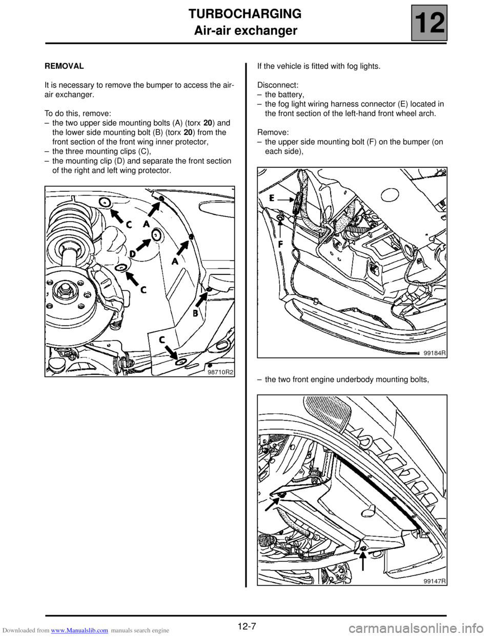
It is necessary to remove the bumper to access the air-
air exchanger.
To do this, remove:
– the two upper side mounting bolts (A) (torx 20) and
the lower side mounting bolt (B) (torx 20) from the
front section of the front wing inner protector,
– the three mounting clips (C),
– the mounting clip (D) and separate the front section
of the right and left wing protector.If the vehicle is fitted with fog lights.
Disconnect:
– the battery,
– the fog light wiring harness connector (E) located in
the front section of the left-hand front wheel arch.
Remove:
– the upper side mounting bolt (F) on the bumper (on
each side),
– the two front engine underbody mounting bolts,
98710R2
99184R
99147R
Page 46 of 118
Downloaded from www.Manualslib.com manuals search engine TURBOCHARGING
Air-air exchanger
12
12-8
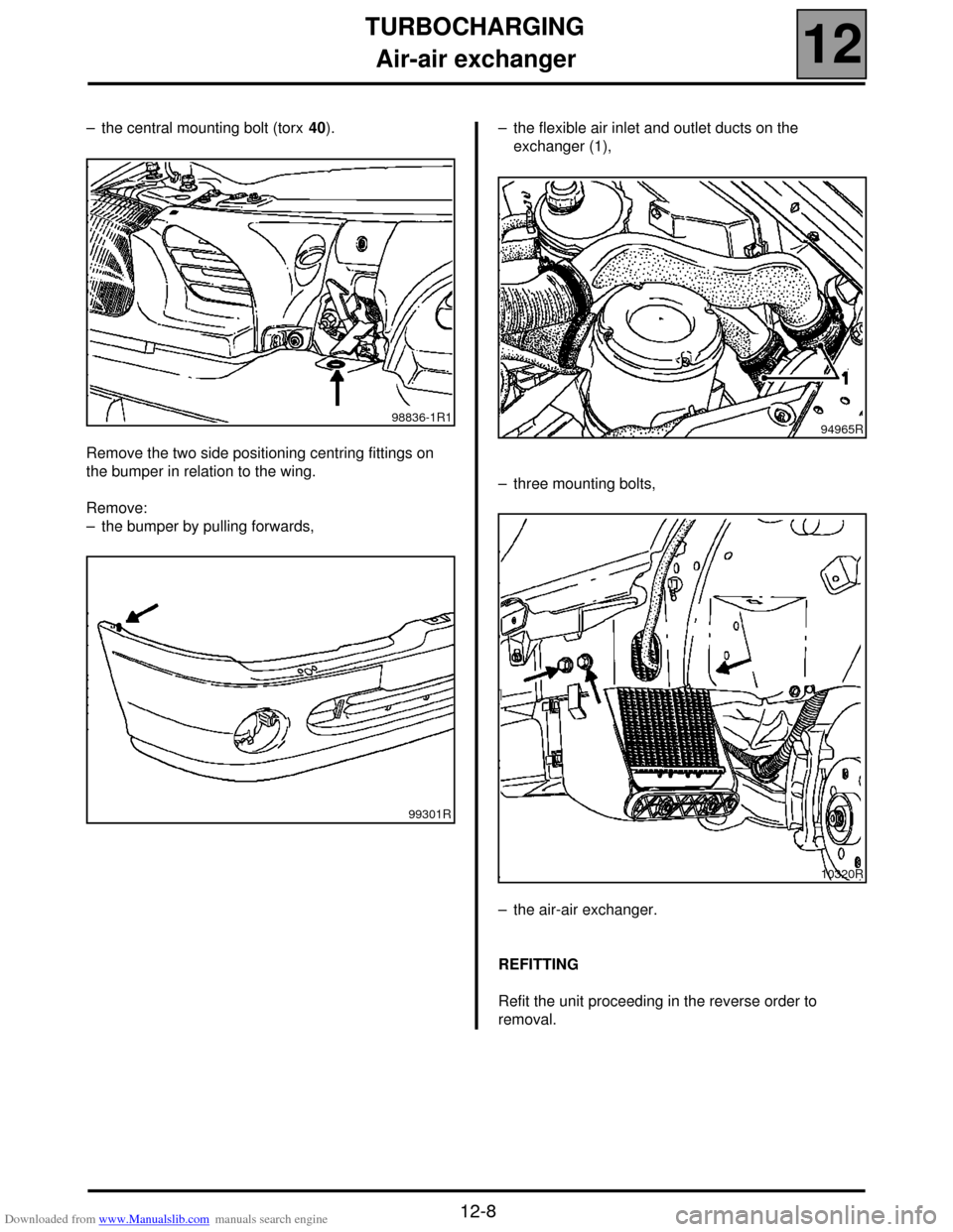
– the central mounting bolt (torx 40).
Remove the two side positioning centring fittings on
the bumper in relation to the wing.
Remove:
– the bumper by pulling forwards,– the flexible air inlet and outlet ducts on the
exchanger (1),
– three mounting bolts,
– the air-air exchanger.
REFITTING
Refit the unit proceeding in the reverse order to
removal.
98836-1R1
99301R94965R
10320R