torque RENAULT SCENIC 2000 J64 / 1.G Technical Note 3426A Owner's Manual
[x] Cancel search | Manufacturer: RENAULT, Model Year: 2000, Model line: SCENIC, Model: RENAULT SCENIC 2000 J64 / 1.GPages: 118, PDF Size: 1.5 MB
Page 87 of 118
Downloaded from www.Manualslib.com manuals search engine DIESEL EQUIPMENT
Injectors
13
13-36
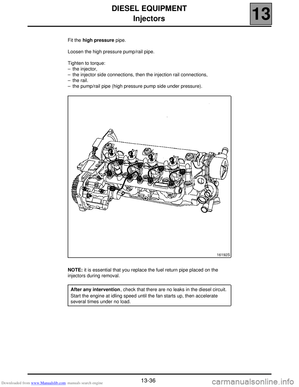
Fit the high pressure pipe.
Loosen the high pressure pump/rail pipe.
Tighten to torque:
– the injector,
– the injector side connections, then the injection rail connections,
– the rail.
– the pump/rail pipe (high pressure pump side under pressure).
NOTE: it is essential that you replace the fuel return pipe placed on the
injectors during removal.
16192S
After any intervention, check that there are no leaks in the diesel circuit.
Start the engine at idling speed until the fan starts up, then accelerate
several times under no load.
Page 89 of 118
Downloaded from www.Manualslib.com manuals search engine DIESEL EQUIPMENT
Pressure sensor
13
13-38
Pressure sensor
TIGHTENING TORQUES (In daN.m or/and°)
Pressure sensor 3.5 ± 0.5
IMPORTANT: before any intervention, connect
the after-sales diagnostic tool, query the injection
computer and check that the injection rail is not
under pressure. Take note of the fuel temperature.
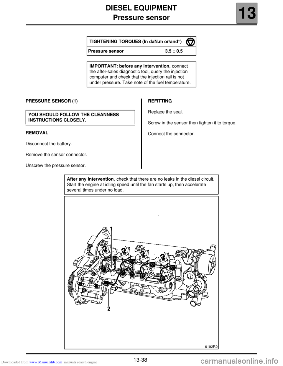
PRESSURE SENSOR (1)
REMOVAL
Disconnect the battery.
Remove the sensor connector.
Unscrew the pressure sensor.REFITTING
Replace the seal.
Screw in the sensor then tighten it to torque.
Connect the connector. YOU SHOULD FOLLOW THE CLEANNESS
INSTRUCTIONS CLOSELY.
After any intervention, check that there are no leaks in the diesel circuit.
Start the engine at idling speed until the fan starts up, then accelerate
several times under no load.
16192R2
Page 90 of 118
Downloaded from www.Manualslib.com manuals search engine DIESEL EQUIPMENT
Pressure regulator
13
13-39
Pressure regulator
TIGHTENING TORQUES (In daN.m or/and °)
Regulator bolt 0.9 ± 0.1
IMPORTANT: before any intervention, connect
the after-sales diagnostic tool, query the injection
computer and check that the injection rail is not
under pressure. Take note of the fuel temperature.
PRESSURE REGULATOR (2)
REMOVAL
Disconnect the battery.
Remove the regulator connector.
Remove the retaining bracket for the diesel
temperature sensor.
Unscrew the regulator mounting bolts.
Remove the regulator by turning in an anticlockwise
direction (do not use any tools as a lever when
removing the pump regulator).REFITTING
Change the seals.
Dampen the seals with clean diesel.
Replace the regulator in the pump by turning it in an
anticlockwise direction (do not use any tools as a lever
when replacing the pump regulator).
Fit the mounting bolts then tighten to torque.
Connect the connector. YOU SHOULD FOLLOW THE CLEANNESS
INSTRUCTIONS CLOSELY.
After any intervention, check that there are no leaks in the diesel circuit.
Start the engine at idling speed until the fan starts up, then accelerate
several times under no load.
Page 105 of 118
Downloaded from www.Manualslib.com manuals search engine COOLING SYSTEM
Thermal plunger unit
19
19-3
Thermal plunger unit
REMOVAL
Put the vehicle on a 2 post lift.
Disconnect the battery.
Remove the engine undertray.
Position the hose clips at the inlet and outlet of the
thermal plunger mounting unit (plugs).
Disconnect the hoses on this unit.
Remove the mounting bolt for the thermal plunger
support unit as well as the supply wires and remove
the unit.
REFITTING
The plugs are tightened in the usual fashion.
Refitting is the reverse of removal.
Top up the coolant and bleed the cooling circuit (see
section 19 "Filling - bleeding"). SPECIAL TOOLING REQUIRED
Mot. 453 -01
Mot. 1202
Mot. 1448Hose clamp pliers set
Hose clip pliers
Long nose pliers for hose clips
TIGHTENING TORQUES (in daN.m)
Thermal plungers 2
Page 107 of 118
Downloaded from www.Manualslib.com manuals search engine COOLING SYSTEM
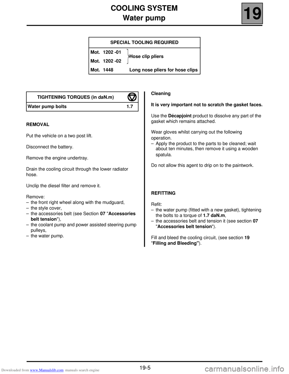
Water pump
19
19-5
Water pump
REMOVAL
Put the vehicle on a two post lift.
Disconnect the battery.
Remove the engine undertray.
Drain the cooling circuit through the lower radiator
hose.
Unclip the diesel filter and remove it.
Remove:
– the front right wheel along with the mudguard,
– the style cover,
– the accessories belt (see Section 07 "Accessories
belt tension"),
– the coolant pump and power assisted steering pump
pulleys,
– the water pump.Cleaning
It is very important not to scratch the gasket faces.
Use the Décapjoint product to dissolve any part of the
gasket which remains attached.
Wear gloves whilst carrying out the following
operation.
– Apply the product to the parts to be cleaned; wait
about ten minutes, then remove it using a wooden
spatula.
Do not allow this agent to drip on to the paintwork.
REFITTING
Refit:
– the water pump (fitted with a new gasket), tightening
the bolts to a torque of 1.7 daN.m,
– the accessories belt and tension it (see section 07
"Accessories belt tension").
Fill and bleed the cooling circuit, (see section 19
"Filling and Bleeding"). SPECIAL TOOLING REQUIRED
Mot. 1202 -01
Hose clip pliers
Mot. 1202 -02
Mot. 1448 Long nose pliers for hose clips
TIGHTENING TORQUES (in daN.m)
Water pump bolts 1.7
Page 108 of 118
Downloaded from www.Manualslib.com manuals search engine ENGINE MOUNTING
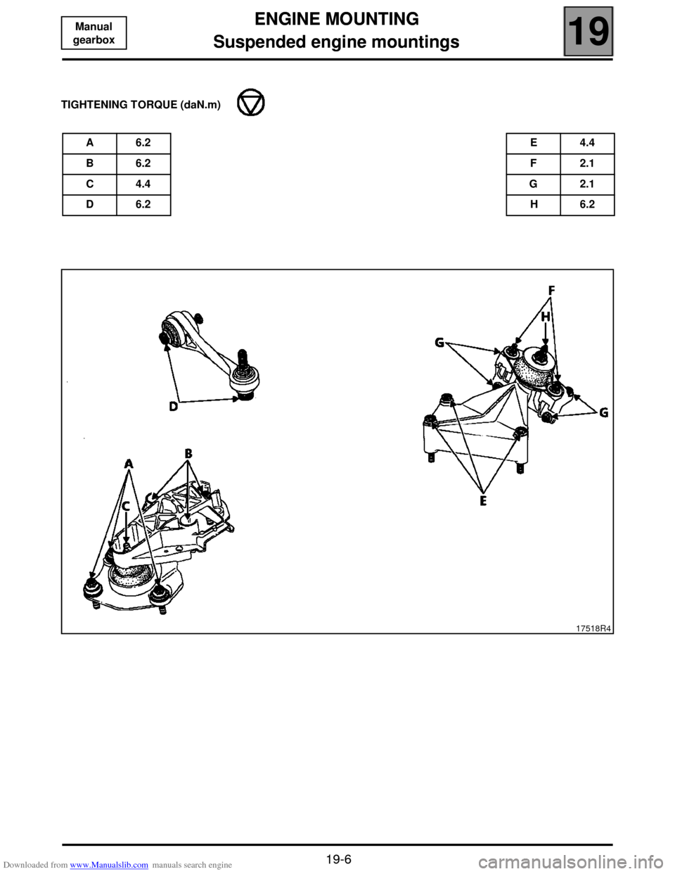
Suspended engine mountings
19
19-6
Manual
gearbox1319 ENGINE MOUNTING
Suspended engine mountings
TIGHTENING TORQUE (daN.m)
A 6.2E 4.4
B 6.2F 2.1
C 4.4G 2.1
D 6.2H 6.2
17518R4
Page 109 of 118
Downloaded from www.Manualslib.com manuals search engine EXHAUST
Catalytic converter
19
19-7
1419 EXHAUST
Catalytic converter
Disconnect the battery and put the vehicle on a two
post lift.
Fit a flywheel immobiliser.
Loosen the catalytic converter/precatalytic converter
mountings.
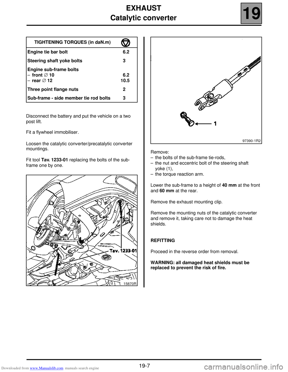
Fit tool Tav. 1233-01 replacing the bolts of the sub-
frame one by one.Remove:
– the bolts of the sub-frame tie-rods,
– the nut and eccentric bolt of the steering shaft
yoke (1),
– the torque reaction arm.
Lower the sub-frame to a height of 40 mm at the front
and 60 mm at the rear.
Remove the exhaust mounting clip.
Remove the mounting nuts of the catalytic converter
and remove it, taking care not to damage the heat
shields.
REFITTING
Proceed in the reverse order from removal.
WARNING: all damaged heat shields must be
replaced to prevent the risk of fire. TIGHTENING TORQUES (in daN.m)
Engine tie bar bolt 6.2
Steering shaft yoke bolts 3
Engine sub-frame bolts
–front ∅ 10
–rear ∅ 12 6.2
10.5
Three point flange nuts 2
Sub-frame - side member tie rod bolts 3
15870R
97390-1R2
Page 116 of 118
Downloaded from www.Manualslib.com manuals search engine AIR CONDITIONING
Pressure relief valve
62
62-5
SCENIC Pressure relief valve
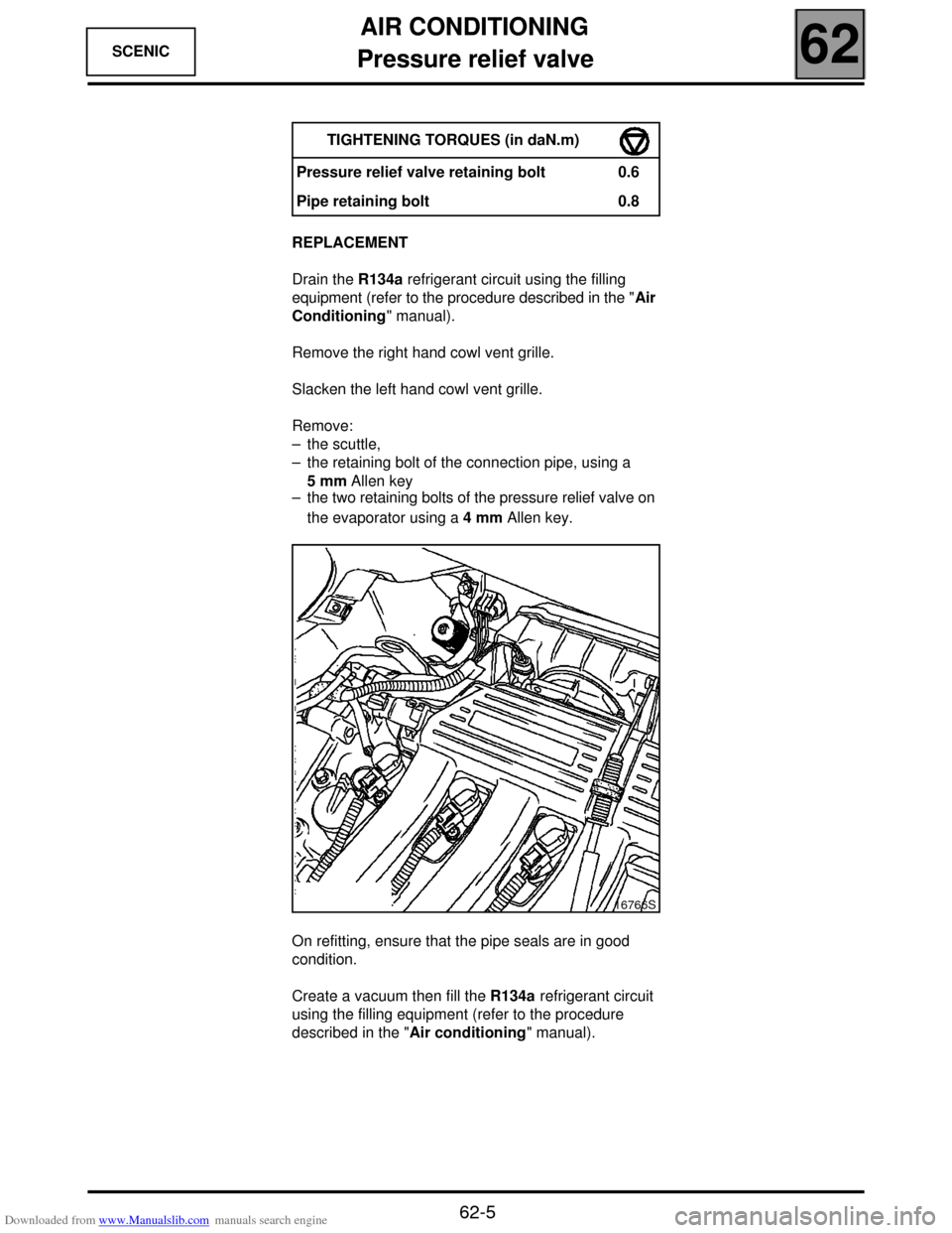
REPLACEMENT
Drain the R134a refrigerant circuit using the filling
equipment (refer to the procedure described in the "Air
Conditioning" manual).
Remove the right hand cowl vent grille.
Slacken the left hand cowl vent grille.
Remove:
– the scuttle,
– the retaining bolt of the connection pipe, using a
5 mm Allen key
– the two retaining bolts of the pressure relief valve on
the evaporator using a 4 mm Allen key.
On refitting, ensure that the pipe seals are in good
condition.
Create a vacuum then fill the R134a refrigerant circuit
using the filling equipment (refer to the procedure
described in the "Air conditioning" manual). TIGHTENING TORQUES (in daN.m)
Pressure relief valve retaining bolt 0.6
Pipe retaining bolt 0.8
16766S