engine oil RENAULT SCENIC 2000 J64 / 1.G Technical Note 3426A Workshop Manual
[x] Cancel search | Manufacturer: RENAULT, Model Year: 2000, Model line: SCENIC, Model: RENAULT SCENIC 2000 J64 / 1.GPages: 118, PDF Size: 1.5 MB
Page 2 of 118
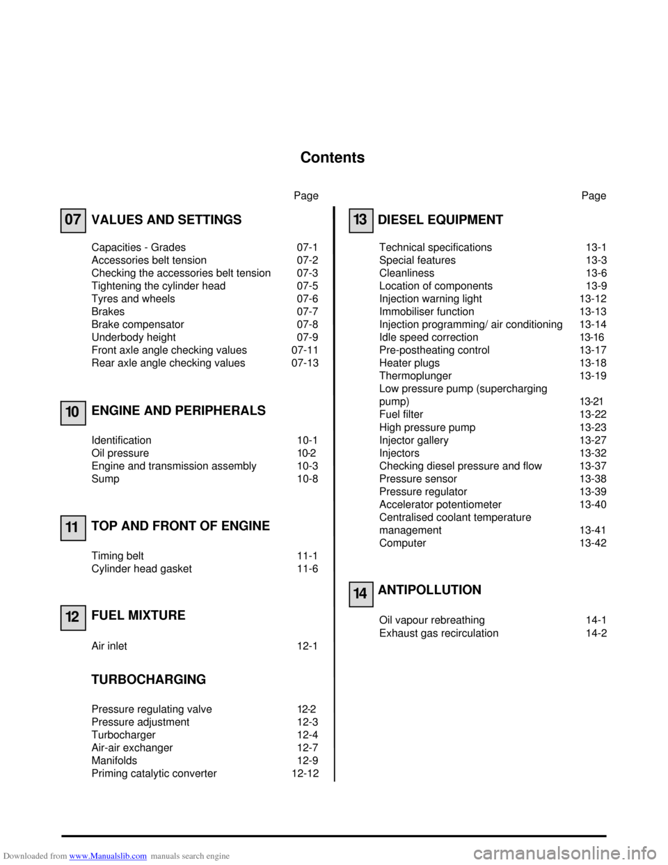
Downloaded from www.Manualslib.com manuals search engine Contents
Page
07
10
11
12
VALUES AND SETTINGS
Capacities - Grades 07-1
Accessories belt tension 07-2
Checking the accessories belt tension 07-3
Tightening the cylinder head 07-5
Tyres and wheels 07-6
Brakes 07-7
Brake compensator 07-8
Underbody height 07-9
Front axle angle checking values 07-11
Rear axle angle checking values 07-13
ENGINE AND PERIPHERALS
Identification 10-1
Oil pressure 10-2
Engine and transmission assembly 10-3
Sump 10-8
TOP AND FRONT OF ENGINE
Timing belt 11-1
Cylinder head gasket 11-6
FUEL MIXTURE
Air inlet 12-1
TURBOCHARGING
Pressure regulating valve 12-2
Pressure adjustment 12-3
Turbocharger 12-4
Air-air exchanger 12-7
Manifolds 12-9
Priming catalytic converter 12-12Page
13
14
DIESEL EQUIPMENT
Technical specifications 13-1
Special features 13-3
Cleanliness 13-6
Location of components 13-9
Injection warning light 13-12
Immobiliser function 13-13
Injection programming/ air conditioning 13-14
Idle speed correction13-16
Pre-postheating control 13-17
Heater plugs 13-18
Thermoplunger 13-19
Low pressure pump (supercharging
pump)13-21
Fuel filter 13-22
High pressure pump 13-23
Injector gallery 13-27
Injectors 13-32
Checking diesel pressure and flow 13-37
Pressure sensor 13-38
Pressure regulator 13-39
Accelerator potentiometer 13-40
Centralised coolant temperature
management 13-41
Computer 13-42
ANTIPOLLUTION
Oil vapour rebreathing 14-1
Exhaust gas recirculation 14-2
Page 4 of 118
Downloaded from www.Manualslib.com manuals search engine VALUES AND SETTINGS
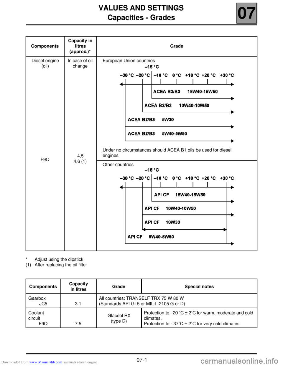
Capacities - Grades
07
107
VALUES AND SETTINGS
Capacities - Grades
* Adjust using the dipstick
(1) After replacing the oil filterComponentsCapacity in
litres
(approx.)*Grade
Diesel engine
(oil)
F9QIn case of oil
change
4,5
4,6 (1)European Union countries
Under no circumstances should ACEA B1 oils be used for diesel
engines
Other countries
ComponentsCapacity
in litresGrade Special notes
Gearbox
JC5 3.1All countries: TRANSELF TRX 75 W 80 W
(Standards API GL5 or MIL-L 2105 G or D)
Coolant
circuit
F9Q 7.5Glacéol RX
(type D)Protection to - 20 ˚C ± 2˚C for warm, moderate and cold
climates.
Protection to - 37˚C ± 2˚C for very cold climates.
07-1
Page 8 of 118
Downloaded from www.Manualslib.com manuals search engine VALUES AND SETTINGS
Tightening the cylinder head
07
07-5
Tightening the cylinder head
METHOD FOR TIGHTENING THE CYLINDER HEAD
REMINDER: in order to tighten the bolts correctly, use
a syringe to remove any oil which may have entered
the cylinder head mounting bolt holes.
All the cylinder head bolts must always be changed
after removal. There is no cylinder head retightening
operation.
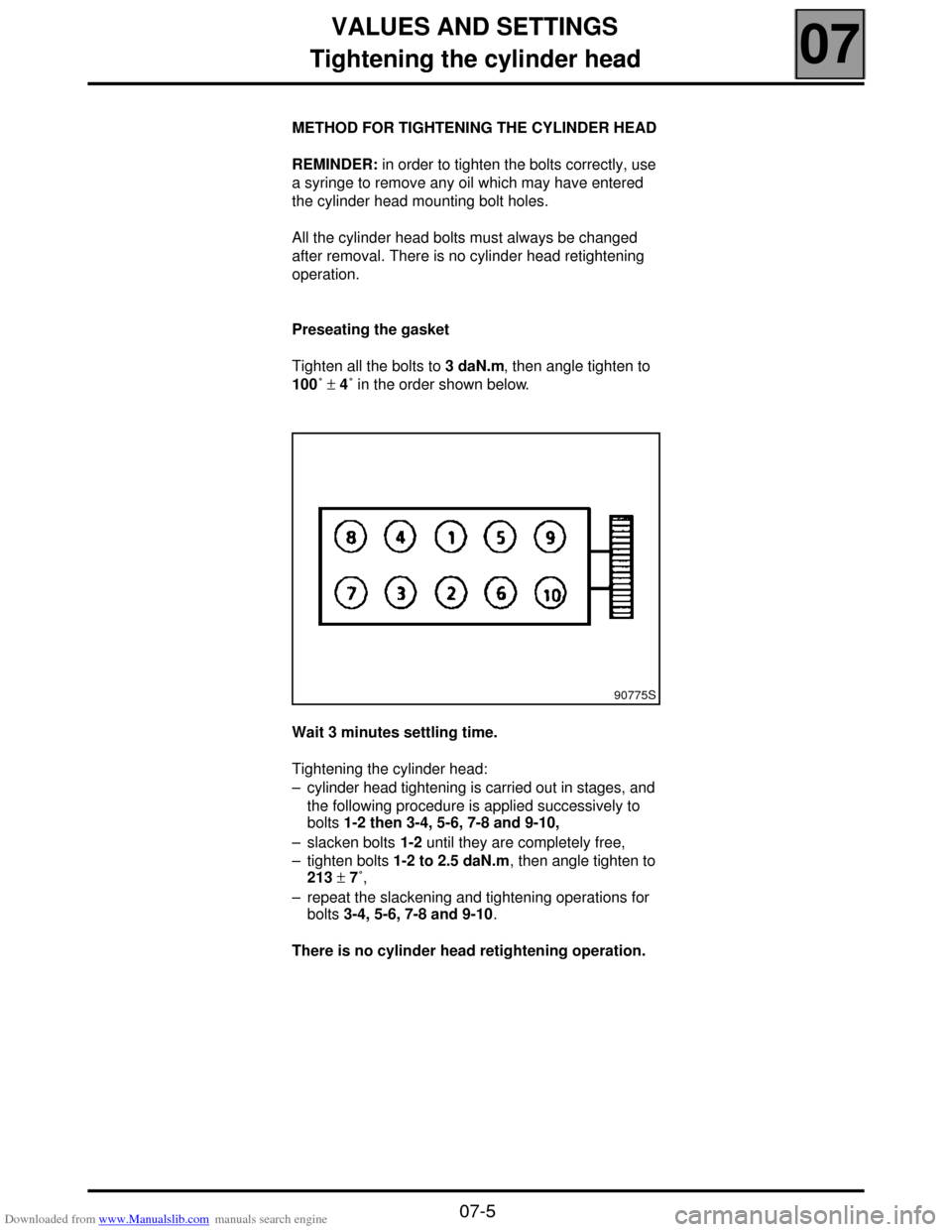
Preseating the gasket
Tighten all the bolts to 3 daN.m, then angle tighten to
100˚ ± 4˚ in the order shown below.
Wait 3 minutes settling time.
Tightening the cylinder head:
– cylinder head tightening is carried out in stages, and
the following procedure is applied successively to
bolts 1-2 then 3-4, 5-6, 7-8 and 9-10,
– slacken bolts 1-2 until they are completely free,
– tighten bolts 1-2 to 2.5 daN.m, then angle tighten to
213 ± 7˚,
– repeat the slackening and tightening operations for
bolts 3-4, 5-6, 7-8 and 9-10.
There is no cylinder head retightening operation.
90775S
Page 18 of 118
Downloaded from www.Manualslib.com manuals search engine ENGINE AND PERIPHERALS
Oil pressure
10
10-2
Oil pressure
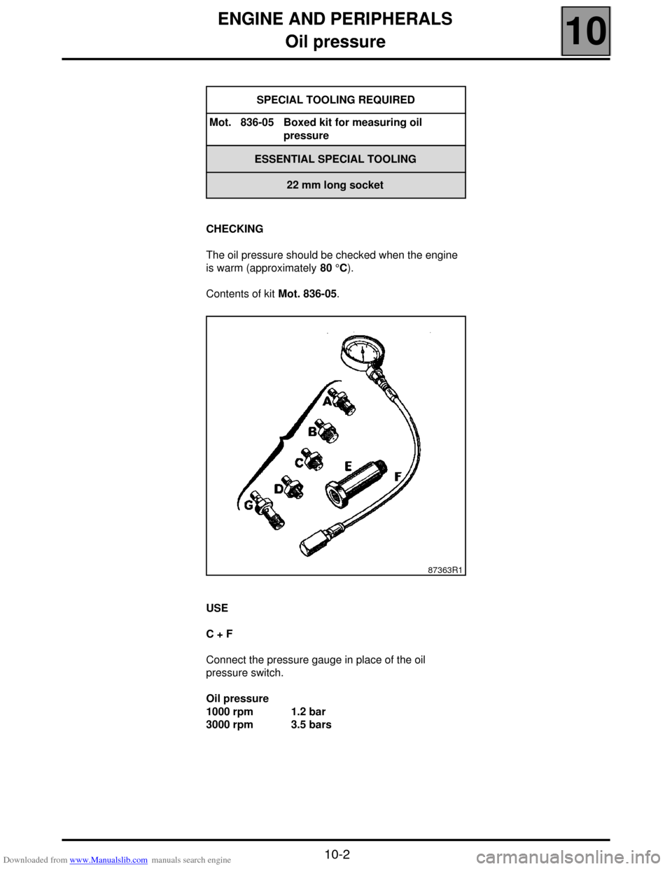
CHECKING
The oil pressure should be checked when the engine
is warm (approximately 80 °C).
Contents of kit Mot. 836-05.
USE
C + F
Connect the pressure gauge in place of the oil
pressure switch.
Oil pressure
1000 rpm 1.2 bar
3000 rpm 3.5 barsSPECIAL TOOLING REQUIRED
Mot. 836-05 Boxed kit for measuring oil
pressure
ESSENTIAL SPECIAL TOOLING
22 mm long socket
87363R1
Page 23 of 118
Downloaded from www.Manualslib.com manuals search engine ENGINE AND PERIPHERALS
Engine and transmission assembly
10
10-7
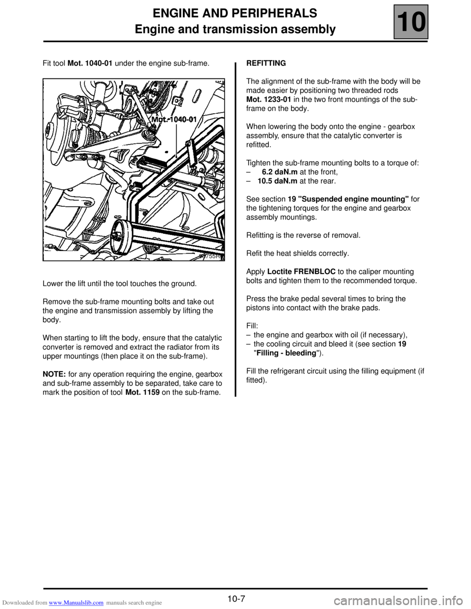
Fit tool Mot. 1040-01 under the engine sub-frame.
Lower the lift until the tool touches the ground.
Remove the sub-frame mounting bolts and take out
the engine and transmission assembly by lifting the
body.
When starting to lift the body, ensure that the catalytic
converter is removed and extract the radiator from its
upper mountings (then place it on the sub-frame).
NOTE: for any operation requiring the engine, gearbox
and sub-frame assembly to be separated, take care to
mark the position of tool Mot. 1159 on the sub-frame.REFITTING
The alignment of the sub-frame with the body will be
made easier by positioning two threaded rods
Mot. 1233-01 in the two front mountings of the sub-
frame on the body.
When lowering the body onto the engine - gearbox
assembly, ensure that the catalytic converter is
refitted.
Tighten the sub-frame mounting bolts to a torque of:
– 6.2 daN.m at the front,
–10.5 daN.m at the rear.
See section 19 "Suspended engine mounting" for
the tightening torques for the engine and gearbox
assembly mountings.
Refitting is the reverse of removal.
Refit the heat shields correctly.
Apply Loctite FRENBLOC to the caliper mounting
bolts and tighten them to the recommended torque.
Press the brake pedal several times to bring the
pistons into contact with the brake pads.
Fill:
– the engine and gearbox with oil (if necessary),
– the cooling circuit and bleed it (see section 19
"Filling - bleeding").
Fill the refrigerant circuit using the filling equipment (if
fitted).
98755R1
Page 26 of 118
Downloaded from www.Manualslib.com manuals search engine ENGINE AND PERIPHERALS
Sump
10
10-10
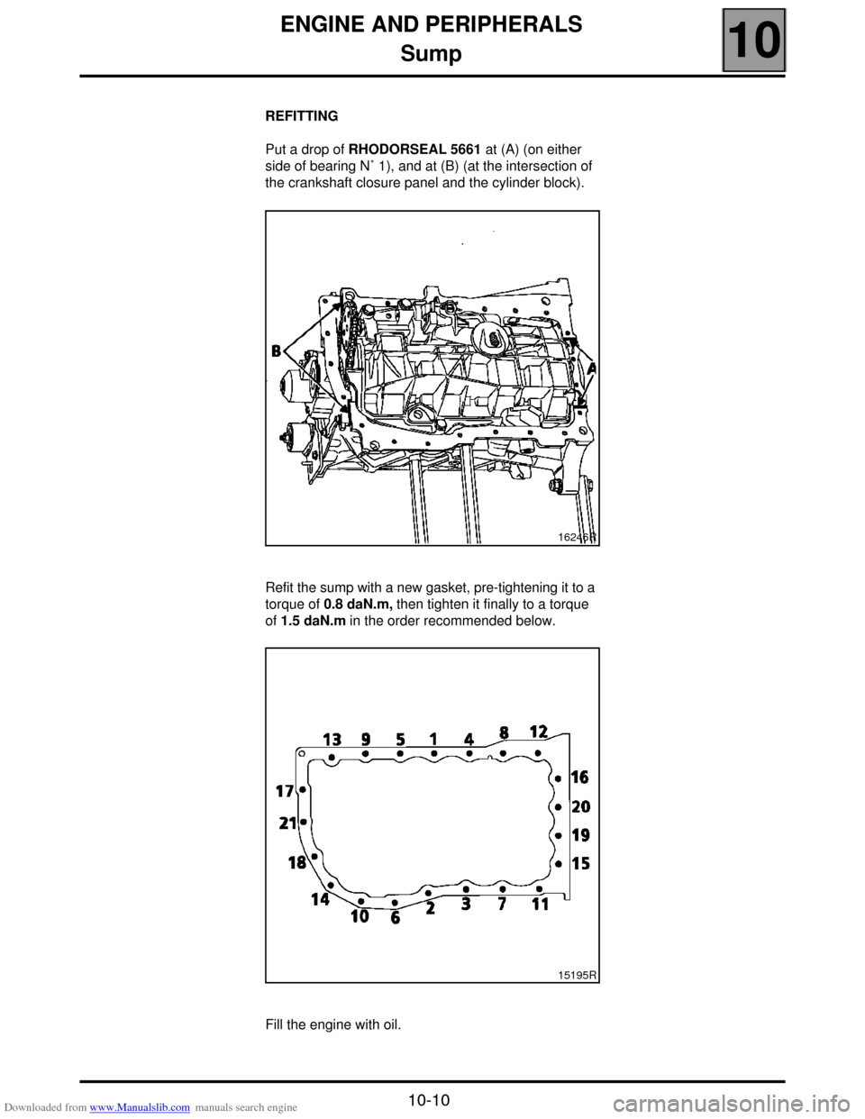
REFITTING
Put a drop of RHODORSEAL 5661 at (A) (on either
side of bearing N˚ 1), and at (B) (at the intersection of
the crankshaft closure panel and the cylinder block).
Refit the sump with a new gasket, pre-tightening it to a
torque of 0.8 daN.m, then tighten it finally to a torque
of 1.5 daN.m in the order recommended below.
Fill the engine with oil.
16246R
15195R
Page 34 of 118
Downloaded from www.Manualslib.com manuals search engine TOP AND FRONT OF ENGINE
Cylinder head gasket
11
11 - 8
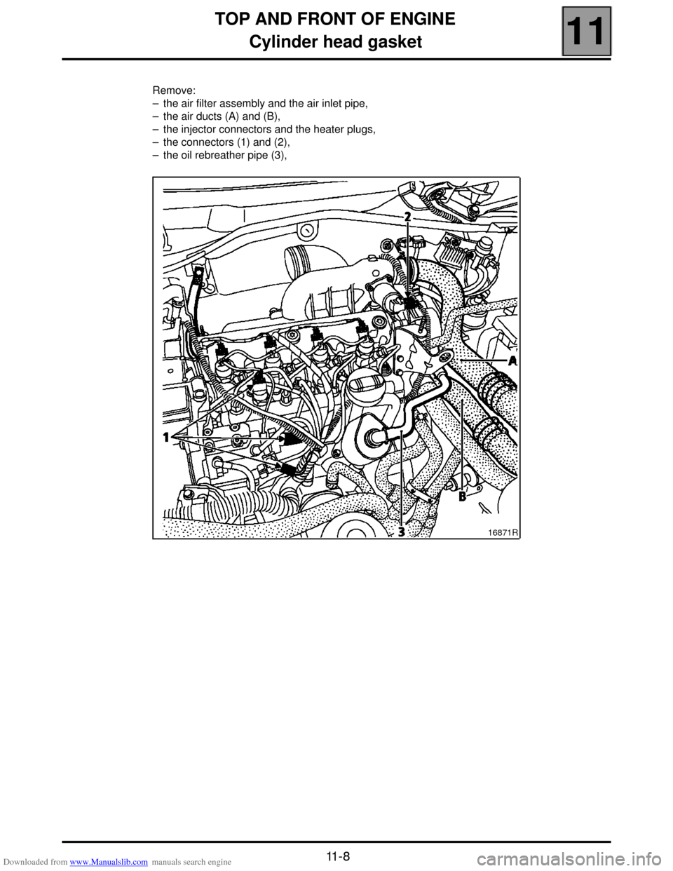
Remove:
– the air filter assembly and the air inlet pipe,
– the air ducts (A) and (B),
– the injector connectors and the heater plugs,
– the connectors (1) and (2),
– the oil rebreather pipe (3),
16871R
Page 36 of 118
Downloaded from www.Manualslib.com manuals search engine TOP AND FRONT OF ENGINE
Cylinder head gasket
11
11-10
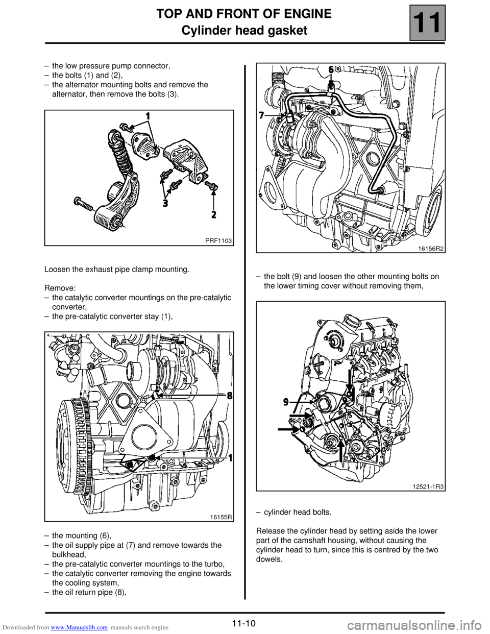
– the low pressure pump connector,
– the bolts (1) and (2),
– the alternator mounting bolts and remove the
alternator, then remove the bolts (3).
Loosen the exhaust pipe clamp mounting.
Remove:
– the catalytic converter mountings on the pre-catalytic
converter,
– the pre-catalytic converter stay (1),
– the mounting (6),
– the oil supply pipe at (7) and remove towards the
bulkhead,
– the pre-catalytic converter mountings to the turbo,
– the catalytic converter removing the engine towards
the cooling system,
– the oil return pipe (8),– the bolt (9) and loosen the other mounting bolts on
the lower timing cover without removing them,
– cylinder head bolts.
Release the cylinder head by setting aside the lower
part of the camshaft housing, without causing the
cylinder head to turn, since this is centred by the two
dowels.
PRF1103
16155R
16156R2
12521-1R3
Page 37 of 118
Downloaded from www.Manualslib.com manuals search engine TOP AND FRONT OF ENGINE
Cylinder head gasket
11
11-11
CLEANING
It is very important not to scratch the gasket faces
of any aluminium component.
Use the Décapjoint product to dissolve any part of the
gasket which remains attached.
W ear gloves whilst carrying out the following
operation.
– Apply the product to the parts to be cleaned; wait
about ten minutes, then remove it using a wooden
spatula.
W e must draw your attention to the care which
must be taken during this operation, to prevent
any foreign bodies from being introduced into the
oil ways (ducts located in the cylinder block and in
the cylinder head).
CHECKING THE GASKET FACE
Check for gasket face bow using a straight edge and a
set of shims.
Maximum deformation: 0.05 mm.
No regrinding of the cylinder head is permitted.
Check the cylinder head for cracks.Checking piston protrusion
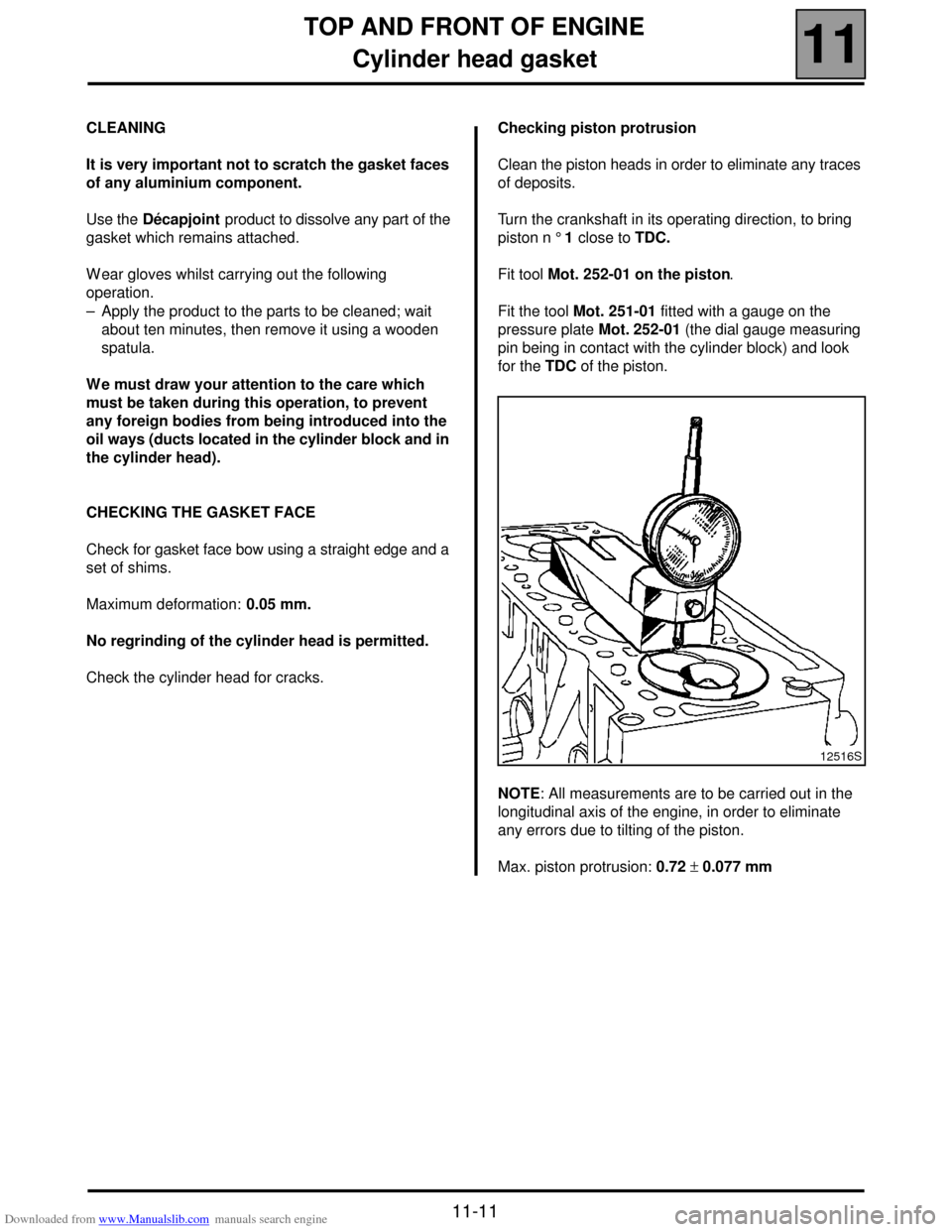
Clean the piston heads in order to eliminate any traces
of deposits.
Turn the crankshaft in its operating direction, to bring
piston n ° 1 close to TDC.
Fit tool Mot. 252-01 on the piston.
Fit the tool Mot. 251-01 fitted with a gauge on the
pressure plate Mot. 252-01 (the dial gauge measuring
pin being in contact with the cylinder block) and look
for the TDC of the piston.
NOTE: All measurements are to be carried out in the
longitudinal axis of the engine, in order to eliminate
any errors due to tilting of the piston.
Max. piston protrusion: 0.72 ± 0.077 mm
12516S
Page 42 of 118
Downloaded from www.Manualslib.com manuals search engine TURBOCHARGING
Turbocharger
12
12-4
Turbocharger
SPECIAL TOOLING REQUIRED
Elé. 1294 -01 Tool for removing windscreen
wiper arms
REMOVAL
NOTE: to slacken the turbocharger mounting nuts
more easily on the exhaust manifold, it is useful to
spray a releasing agent on the nuts when still hot, just
before removal.
Disconnect the battery.
Remove the engine cover.
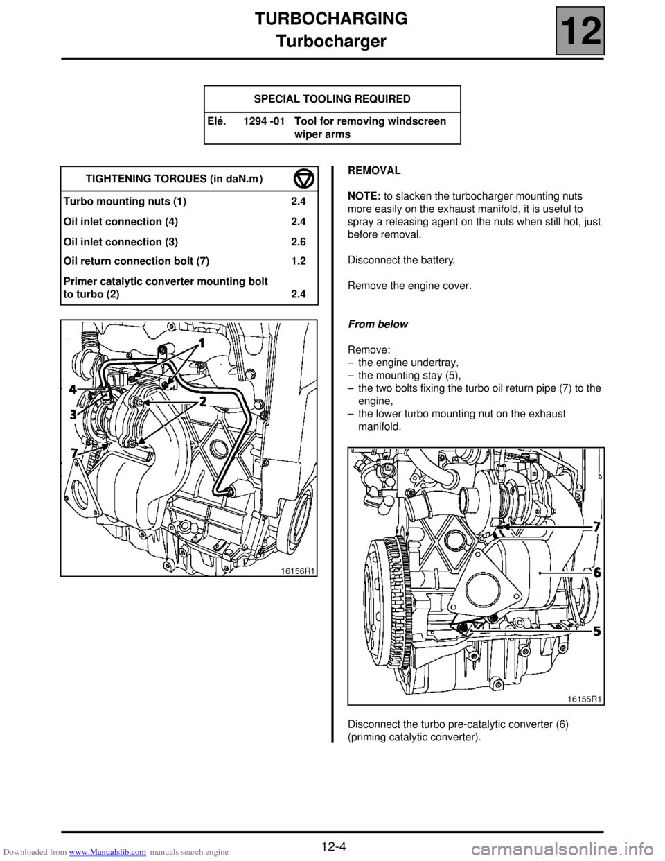
From below
Remove:
– the engine undertray,
– the mounting stay (5),
– the two bolts fixing the turbo oil return pipe (7) to the
engine,
– the lower turbo mounting nut on the exhaust
manifold.
Disconnect the turbo pre-catalytic converter (6)
(priming catalytic converter). TIGHTENING TORQUES (in daN.m )
Turbo mounting nuts (1) 2.4
Oil inlet connection (4) 2.4
Oil inlet connection (3) 2.6
Oil return connection bolt (7) 1.2
Primer catalytic converter mounting bolt
to turbo (2) 2.4
16156R1
16155R1