change time RENAULT SCENIC 2006 J84 / 2.G Multimedia Nav 4R User Guide
[x] Cancel search | Manufacturer: RENAULT, Model Year: 2006, Model line: SCENIC, Model: RENAULT SCENIC 2006 J84 / 2.GPages: 86, PDF Size: 0.29 MB
Page 20 of 86
MULTIMEDIA
Fault finding - Interpretation of faults
86C
86C-19
NAV 4R
Program no.: 0000
Vdiag No.: 24
DF021
PRESENT
COMPUTER CONFIGURATION
1.DEF : Computer configuration not performed
NOTESNone.
Configure the system (see Configuration and programming).
Note:
After configuring, switch off the ignition, wait 2 minutes then switch on the ignition again to allow the configuration
to register.
Check that the configurations have been correctly registered by reading configurations LC001 Vehicle Type and
LC005 CD changer.
If the fault is still present, contact the Techline.
AFTER REPAIRDeal with any faults displayed by the diagnostic tool.
Clear the faults from the 4R radio navigation computer memory using command RZ001
Fault memory.
NAV4R_V24_DF021P
Page 21 of 86
MULTIMEDIA
Fault finding - Interpretation of faults
86C
86C-20
NAV 4R
Program no.: 0000
Vdiag No.: 24
DF024
PRESENT
OR
STOREDNO INSTRUMENT PANEL MULTIPLEX SIGNAL
1.DEF : No communication with the instrument panel
NOTESOrder of priority in the event of more than one fault:
If faults DF024 No instrument panel multiplex signal and DF026 No fold-out unit
multiplex signal are present, run command VP005 Computer configuration to
reconfigure the system (see Configuration and programming).
Conditions for applying fault finding procedures to stored faults:
Apply this fault finding procedure if the fault reappears as present or stored after it has
been cleared and the ignition has been switched off and on again.
Special note:
Apply this fault procedure only for vehicles equipped with an instrument panel dot
matrix display (Top of the range Mégane II phase 2).
Use the Wiring Diagrams Technical Note for the Mégane II.
Look for any damage to the wiring harness, check the condition and connection of the connectors on
components 261 and 247.
Manipulate the wiring harness in order to produce a change in the fault status (present → stored).
If the connector is faulty and there is a repair procedure (see Technical Note 6015A, Electrical wiring repair,
Wiring: Precautions for repair), repair the connector, otherwise replace the wiring.
Using the universal bornier, check the insulation, continuity and the absence of interference resistance on
the following connections:
●connection code 107W,
●connection code 107X,
between components 261 and 247.
If the connection or connections are faulty and there is a repair procedure (see Technical Note 6015A, Electrical
wiring repair, Wiring: Precautions for repair), repair the wiring, otherwise replace it.
If the fault is still present, run fault finding on the instrument panel (see 83A, Instrument panel) and the multiplex
network (see 88B, Multiplexing).
AFTER REPAIRDeal with any faults displayed by the diagnostic tool.
Clear the faults from the 4R radio navigation computer memory using command RZ001
Fault memory.
NAV4R_V24_DF024
Page 22 of 86
MULTIMEDIA
Fault finding - Interpretation of faults
86C
86C-21
NAV 4R
Program no.: 0000
Vdiag No.: 24
DF026
PRESENT
OR
STOREDNO FOLD-OUT UNIT MULTIPLEX SIGNAL
1.DEF : No communication with the display fold-out unit
NOTESOrder of priority in the event of more than one fault:
If faults DF024 No instrument panel multiplex signal and DF026 No fold-out unit
multiplex signal are present, run command VP005 Computer configuration to
reconfigure the system (see Configuration and programming).
Conditions for applying fault finding procedures to stored faults:
Apply this fault finding procedure if the fault reappears as present or stored after it has
been cleared and the ignition has been switched off and on again.
Special note:
Apply this fault procedure only for vehicles equipped with a fold-out unit (Top of the
range Mégane II phase 2).
Use the Wiring Diagrams Technical Note for the Mégane II.
Look for any damage to the wiring harness, check the condition and connection of the connectors on
components 261 and 1303.
Manipulate the wiring harness in order to produce a change in the fault status (present → stored).
If the connector is faulty and there is a repair procedure (see Technical Note 6015A, Electrical wiring repair,
Wiring: Precautions for repair), repair the connector, otherwise replace the wiring.
Using the universal bornier, check the insulation, continuity and the absence of interference resistance on
the following connections:
●connection code 34GA,
●connection code 34DZ,
●connection code 34GG,
●connection code BCP3,
between components 261 and 1303.
If the connection is faulty and there is a repair procedure (see Technical Note 6015A, Electrical wiring repair,
Wiring: Precautions for repair), repair the wiring, otherwise replace it.
Check for + 12 V on connection BCP3 of the connector of component 1303.
Also check for earth on connection MAN of the connector of component 1303.
If the connection is faulty and there is a repair procedure (see Technical Note 6015A, Electrical wiring repair,
Wiring: Precautions for repair), repair the wiring, otherwise replace it.
If the fault is still present, run fault finding on the multiplex network (see 88B, Multiplexing).
AFTER REPAIRDeal with any faults displayed by the diagnostic tool.
Clear the faults from the 4R radio navigation computer memory using command RZ001
Fault memory.
NAV4R_V24_DF026
Page 23 of 86
MULTIMEDIA
Fault finding - Interpretation of faults
86C
86C-22
NAV 4R
Program no.: 0000
Vdiag No.: 24
DF027
PRESENT
OR
STOREDNO AUDIO CD CHANGER SIGNALS
1.DEF : No communication with the CD changer
NOTESOrder of priority in the event of more than one fault:
Deal with fault DF001 Computer first, if present or stored.
Conditions for applying fault finding procedures to stored faults:
Apply this fault finding procedure if the fault reappears as present or stored after it has
been cleared and the ignition has been switched off and on again.
Special note:
If the vehicle does not have a CD changer, check the 4R radio navigation computer
configuration (see Configuration and programming).
Apply the following fault finding procedure to vehicles equipped with a CD changer.
Use the Wiring Diagram Technical Note for the vehicle concerned.
Look for any damage to the wiring harness, check the condition and connection of the connectors on
components 261 and 1272.
Manipulate the wiring harness in order to produce a change in the fault status (present → stored).
If the connector is faulty and there is a repair procedure (see Technical Note 6015A, Electrical wiring repair,
Wiring: Precautions for repair), repair the connector, otherwise replace the wiring.
Using the universal bornier, check the insulation, continuity and the absence of interference resistance on
the following connections:
●connection code 34AZ,
●connection code 34BA,
●connection code 34BL,
●connection code 34BC,
●connection code 34BD,
●connection code 34BG,
●connection code 34BH,
●connection code 34BK (only for Scénic),
between components 261 and 1272.
If the connection or connections are faulty and there is a repair procedure (see Technical Note 6015A, Electrical
wiring repair, Wiring: Precautions for repair), repair the wiring, otherwise replace it.
If the fault is still present, contact the Techline.
AFTER REPAIRDeal with any faults displayed by the diagnostic tool.
Clear the faults from the 4R radio navigation computer memory using command RZ001
Fault memory.
NAV4R_V24_DF027
Page 24 of 86
MULTIMEDIA
Fault finding - Interpretation of faults
86C
86C-23
NAV 4R
Program no.: 0000
Vdiag No.: 24
DF030
PRESENT
OR
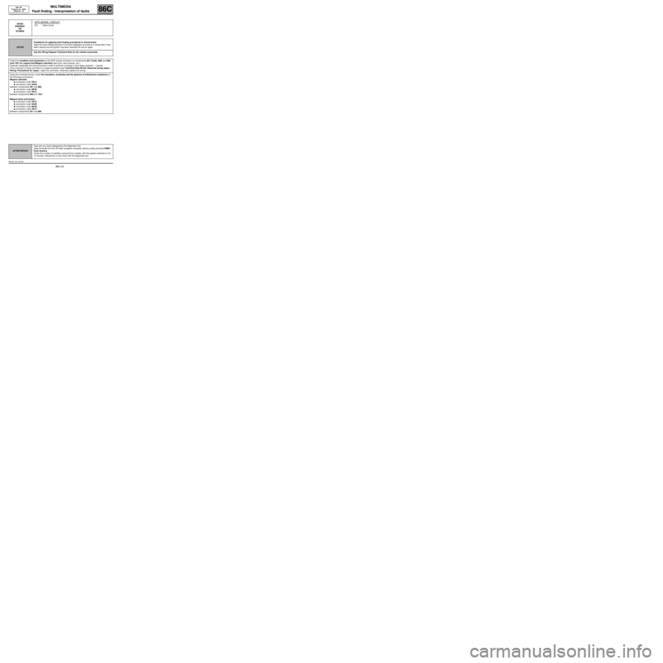
STOREDGPS AERIAL CIRCUIT
CO : Open circuit
NOTESConditions for applying fault finding procedures to stored faults:
Apply this fault finding procedure if the fault reappears as present or stored after it has
been cleared and the ignition has been switched off and on again.
Use the Wiring Diagram Technical Note for the vehicle concerned.
Check the condition and connection of the GPS coaxial connector on components 261 (Trafic: 662) and 886
(and 1551 for Laguna and Mégane cabriolet) (bent pins, bad contacts, etc.).
Carefully manipulate the wiring harness in order to produce a change in fault status (present → stored).
If the connector is faulty and there is a repair procedure (see Technical Note 6015A, Electrical wiring repair,
Wiring: Precautions for repair), repair the connector, otherwise replace the wiring.
Using the universal bornier, check the insulation, continuity and the absence of interference resistance on
the following connections:
Mégane cabriolet:
●connection code TB13,
●connection code 34AN,
between components 261 and 886;
●connection code 46CB,
●connection code TB15,
between components 886 and 1551.
Mégane hatch and Scénic:
●connection code TB13,
●connection code 34AN,
●connection code 46CB,
●connection code TB15,
between components 261 and 886.
AFTER REPAIRDeal with any faults displayed by the diagnostic tool.
Clear the faults from the 4R radio navigation computer memory using command RZ001
Fault memory.
Check the number of satellites received from outside, with the system switched on for
10 minutes, followed by a new check with the diagnostic tool.
NAV4R_V24_DF030
Page 28 of 86
MULTIMEDIA
Fault finding - Interpretation of faults
86C
86C-27
NAV 4R
Program no.: 0000
Vdiag No.: 24
DF034
PRESENT
CD READER
1.DEF : CD unreadable
NOTESSpecial note:
The system enables:
–CD-ROM maps to be displayed,
–the user to listen to commercial audio CDs, CDs burned independently, CDs
containing MP3 files (optional). The CDs are read by the 4R unit's CD player or by
the optional 6-CD changer.
Check that the CD is not scratched.
For a CD-ROM card, change the CD.
For all other types of CD, check that the CD format is compatible with the system.
If the fault is still present, contact the Techline.
AFTER REPAIRDeal with any faults displayed by the diagnostic tool.
Clear the faults from the 4R radio navigation computer memory using command RZ001
Fault memory.
NAV4R_V24_DF034P
Page 29 of 86
MULTIMEDIA
Fault finding - Interpretation of faults
86C
86C-28
NAV 4R
Program no.: 0000
Vdiag No.: 24
DF035
PRESENT
OR
STOREDCOMPUTER/FOLD-OUT UNIT CONNECTION
CO.1 : Short circuit or open circuit to + 12 V
NOTESConditions for applying fault finding procedures to stored faults:
Apply this fault finding procedure if the fault reappears as present or stored after it has
been cleared and the ignition has been switched off and on again.
Special note:
If the vehicle does not have a fold-out unit, check the 4R radio navigation computer
configuration (see Configuration and programming).
The screen does not deploy or there is no display on the instrument panel.
Apply the following fault finding procedure only if the vehicle is equipped with a fold-out
unit and a dot matrix display on the instrument panel (top of the range Mégane II
phase 2).
Use the Wiring Diagrams Technical Note for the Mégane II.
Check the condition and connection of the connectors of components 261, 1303 and 247 (bent pins, bad
contacts, etc.).
If the connector is faulty and there is a repair procedure (see Technical Note 6015A, Electrical wiring repair,
Wiring: Precautions for repair), repair the connector, otherwise replace the wiring.
Manipulate the wiring harness in order to produce a change in the fault status (present → stored).
Check the insulation, continuity and the absence of interference resistance on connection 34GG between
components 261 and 1303.
If the connection is faulty and there is a repair procedure (see Technical Note 6015A, Electrical wiring repair,
Wiring: Precautions for repair), repair the wiring, otherwise replace it.
Check the insulation, continuity and the absence of interference resistance on connection 34GD between
components 247 and 1303.
If the connection is faulty and there is a repair procedure (see Technical Note 6015A, Electrical wiring repair,
Wiring: Precautions for repair), repair the wiring, otherwise replace it.
If the fault is still present, contact the Techline.
AFTER REPAIRDeal with any faults displayed by the diagnostic tool.
Clear the faults from the 4R radio navigation computer memory using command RZ001
Fault memory.
NAV4R_V24_DF035
Page 55 of 86
MULTIMEDIA
Fault finding - Interpretation of parameters86C
86C-54
NAV 4R
Program no.: 0000
Vdiag No.: 24
PR009
ANGULAR POSITION
NOTESThere must be no present or stored faults.
Engine stopped, ignition on.
Use the Wiring Diagram Technical Note for the vehicle concerned.
Remove component 261 (Trafic: 662) without disconnecting the connectors.
Shake the radio/navigation computer vigorously; parameter PR009 Angular position should be above or equal
to 1 d/s.
Each time the 4R radio/navigation computer is at rest, PR009 Angular position should be very close to 0 d/s.
If the parameter does not change, contact the Techline.
AFTER REPAIRRepeat the conformity check from the start.
NAV4R_V24_PR009
Page 58 of 86
MULTIMEDIA
Fault finding - Dealing with commands
86C
86C-57
NAV 4R
Program no.: 0000
Vdiag No.: 24
Fault finding - Dealing with commands
CLEARING
RZ001 Fault memory:
This command is used to clear faults stored in the navigation computer.
ACTIVATIONS
AUDIO tab
AC004 Speaker test:
This command is used to perform a listening test on the speakers.
DISPLAY tab
AC021 Display test:
This command is used to check that the video display is operating correctly. Three colours are displayed on
the screen: Red, green and blue, and a black mosaic on a white background.
USER SELECTION tab
AC022 CD ejection:
This command is used to eject the CD from the CD reader, and not from the CD changer.
Page 63 of 86
MULTIMEDIA
Fault finding - Customer complaints
86C
86C-62
NAV 4R
Program no.: 0000
Vdiag No.: 24
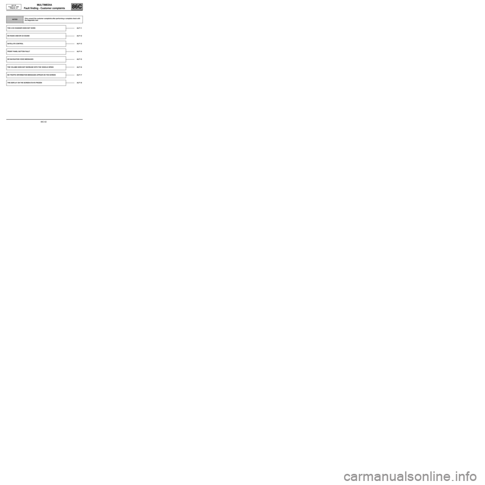
NOTESOnly consult the customer complaints after performing a complete check with
the diagnostic tool.
THE 6 CD CHANGER DOES NOT WORK ALP 11
NO RADIO AND/OR CD SOUND ALP 12
SATELLITE CONTROLALP 13
FRONT PANEL BUTTON FAULT ALP 14
NO NAVIGATION VOICE MESSAGES ALP 15
THE VOLUME DOES NOT INCREASE WITH THE VEHICLE SPEED ALP 16
NO TRAFFIC INFORMATION MESSAGES APPEAR ON THE SCREEN ALP 17
THE DISPLAY ON THE SCREEN STAYS FROZEN ALP 18