change time RENAULT SCENIC 2006 J84 / 2.G Multimedia Nav 4R Workshop Manual
[x] Cancel search | Manufacturer: RENAULT, Model Year: 2006, Model line: SCENIC, Model: RENAULT SCENIC 2006 J84 / 2.GPages: 86, PDF Size: 0.29 MB
Page 1 of 86
Electrical equipment
77 11 322 302
"The repair procedures given by the manufacturer in this document are based on the
technical specifications current when it was prepared.
The procedures may be modified as a result of changes introduced by the
manufacturer in the production of the various component units and accessories from
which his vehicles are constructed."
MARCH 2006
All rights reserved by Renault s.a.s.
EDITION ANGLAISE
Copying or translating, in part or in full, of this document or use of the service part
reference numbering system is forbidden without the prior written authority of
Renault s.a.s.
© Renault s.a.s. 2006
MULTIMEDIA
NAV 4R
Program no.: 0000
Vdiag No.: 24
Fault finding - Introduction 86C - 1
Fault finding - List and location of components 86C - 8
Fault finding - Operating diagram 86C - 11
Fault finding - Functions 86C - 12
Fault finding - Role of components 86C - 13
Fault finding - Configuration and programming 86C - 14
Fault finding - Replacement of components 86C - 15
Fault finding - Fault summary table 86C - 17
Fault finding - Interpretation of faults 86C - 18
Fault finding - Conformity check 86C - 29
Fault finding - Status summary table 86C - 34
Fault finding - Interpretation of statuses 86C - 35
Fault finding - Parameter summary table 86C - 46
Fault finding - Interpretation of parameters 86C - 47
Fault finding - Command summary table 86C - 56
Fault finding - Dealing with commands 86C - 57
Fault finding - Customer complaints 86C - 61
Diagnostic - Fault finding chart 86C - 63
86C
Page 5 of 86
MULTIMEDIA
Fault finding - Introduction
86C
86C-4
NAV 4R
Program no.: 0000
Vdiag No.: 24
4. FAULT FINDING PROCEDURE (continued)
Wiring check
Fault finding problems
Disconnecting the connectors and/or manipulating the wiring harness may temporarily remove the cause of a fault.
Electrical measurements of voltage, resistance and insulation are generally correct, especially if the fault is not
present when the analysis is made (stored fault).
Visual inspection
Look for damage under the bonnet and in the passenger compartment.
Carefully check the fuses, insulation and wiring harness routing.
Look for signs of oxidation.
Tactile inspection
While manipulating the wiring harness, use the diagnostic tool to note any change in fault status from stored to
present.
Check that the connectors are properly locked.
Apply light pressure to the connectors.
Twist the wiring harness.
If there is a change in status, try to locate the source of the fault.
Inspection of each component
Disconnect the connectors and check the appearance of the clips and tabs, as well as the crimping (no crimping on
the insulating section).
Make sure that the clips and tabs are properly locked in the holes.
Check that no clips or tabs have been dislodged during connection.
Check the clip contact pressure using an appropriate model of tab.
Resistance check
Check the continuity of entire lines, then section by section.
Look for a short circuit to earth, to + 12 V or to another wire.
If a fault is detected, repair or replace the wiring harness.
Page 8 of 86
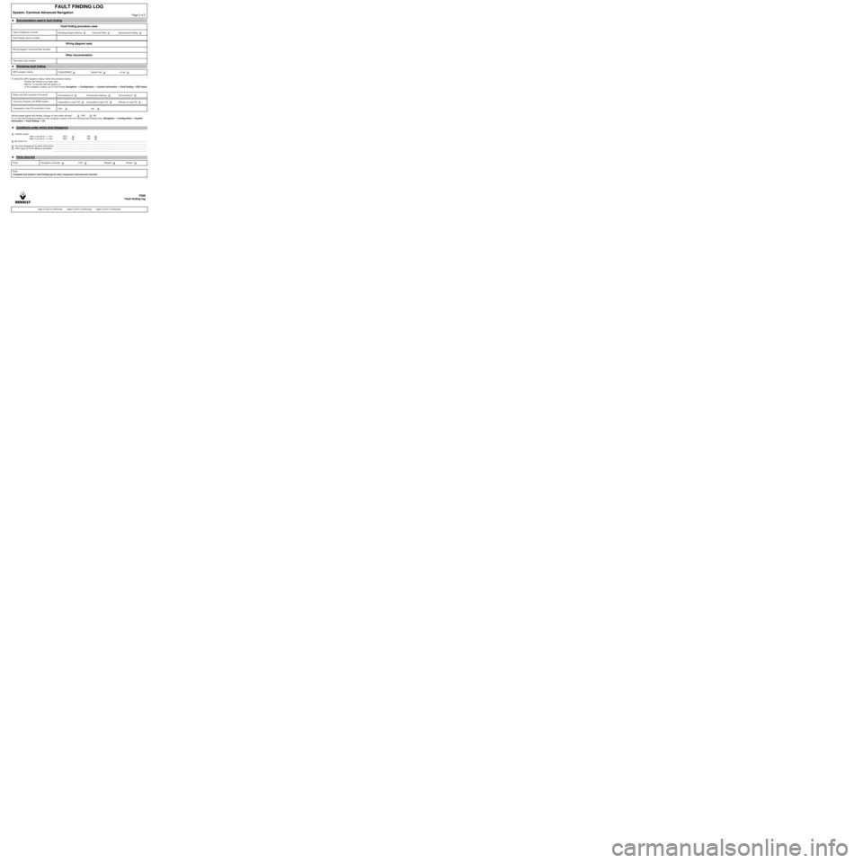
To check the GPS reception status, follow the procedure below:
Position the vehicle in an open area
Wait for 15 minutes with the ignition on
In the navigation system, go to Fault finding: Navigation →→ → →
Configuration →→ → →
System information →→ → →
Fault finding→→ → →
GPS status
Vehicle speed signal fault finding, change of value when driving? YES NO
To run this fault finding procedure on the navigation system, from the following fault finding menu: Navigation →→ → →
Configuration →→ → →
System
information →→ → →
Fault finding →→ → →
I/O
Vehicle restart
after a cut-off of > 1 min: OUT NO
after a cut-off of <1 min: OUT NO
By action on: .................................................................................................................................................................................................
.................................................................................................................................................................................................
The fault disappears by itself (state time): .............................................................................................................. .............................................
Other (give as much detail as possible): ..............................................................................................................................................................
.............................................................................................. ...............................................................
FAULT FINDING LOG
System: Carminat Advanced NavigationPage 2 of 2
â—ŹDocumentation used in fault finding
Fault finding procedure used
Type of diagnostic manual:
Workshop Repair Manual Technical Note Assisted fault finding
Fault finding manual number
Wiring diagram used
Wiring Diagram Technical Note Number:
Other documentation
Title and/or part number:
â—Ź
Workshop fault finding
GPS reception status:
COM.ERROR Search Sat ≥ 3 sat
Status red LED computer front panel:
Permanently off Permanently flashing Permanently lit
Carminat computer (CD-ROM reader):
Impossible to insert CD Impossible to eject CD Refuses to read CD
Cartographic map CD scratched or dirty:
YES NO
â—Ź
Conditions under which fault disappears
â—ŹParts returned
Parts: Navigation computer CCU Keypad Screen
Note:
Complete and submit a fault finding log for each component removed and returned.
FD98
Fault finding log
page to print or photocopy - page to print or photocopy - page to print or photocopy
Page 11 of 86
MULTIMEDIA
Fault finding - List and location of components86C
86C-10
NAV 4R
Program no.: 0000
Vdiag No.: 24
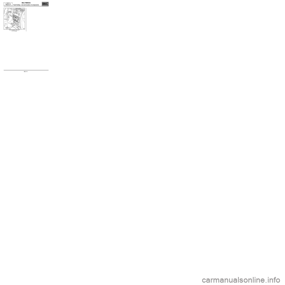
Radio/navigation computer
6 CD changer
Page 12 of 86
MULTIMEDIA
Fault finding - Operating diagram
86C
86C-11
NAV 4R
Program no.: 0000
Vdiag No.: 24
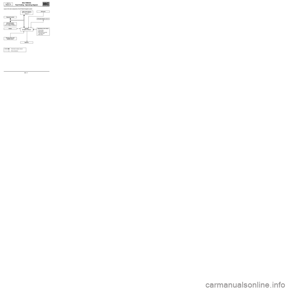
Fault finding - Operating diagram
Layout of the main components of the 4R Radio Navigation system
Video screen fold-out
unit (Only on MĂ©gane II
phase 2)GPS aerial
Diagnostic socket
CD multi-changer (optional)
Instrument panel
(Dot matrix display)
(Only on MĂ©gane II phase 2)
Display 4R Radio
Navigation computerDepending on the vehicle
–Thermometer
–Speed signal
–Seat belt warning light
–+ side light feed
–Radio aerial
Steering wheel radio
satellite control
Speakers
- Multimedia multiplex network
- Wire connections
Page 13 of 86
MULTIMEDIA
Fault finding - Functions
86C
86C-12
NAV 4R
Program no.: 0000
Vdiag No.: 24
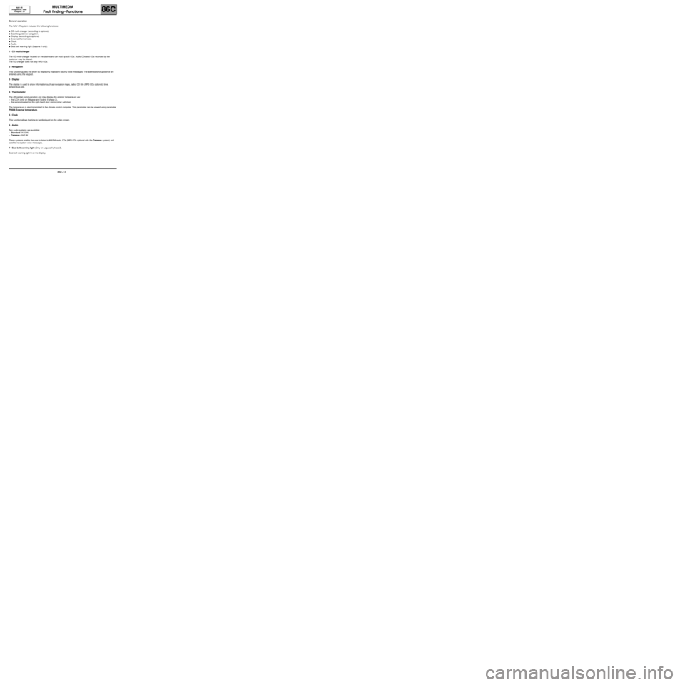
Fault finding - Functions
General operation
The NAV 4R system includes the following functions:
â—ŹCD multi-changer (according to options).
â—ŹSatellite guidance navigation.
â—ŹDisplay (according to options).
â—ŹExternal thermometer.
â—ŹClock.
â—ŹAudio.
â—ŹSeat belt warning light (Laguna II only).
1 - CD multi-changer
The CD multi-changer located on the dashboard can hold up to 6 CDs. Audio CDs and CDs recorded by the
customer may be played.
The CD changer does not play MP3 CDs.
2 - Navigation
This function guides the driver by displaying maps and issuing voice messages. The addresses for guidance are
entered using the keypad.
3 - Display
The display is used to show information such as navigation maps, radio, CD title (MP3 CDs optional), time,
temperature, etc.
4 - Thermometer
The 4R central communication unit may display the exterior temperature via:
–the UCH (only on Mégane and Scénic II phase 2),
–the sensor located on the right-hand door mirror (other vehicles).
The temperature is also transmitted to the climate control computer. This parameter can be viewed using parameter
PR006 External temperature.
5 - Clock
This function allows the time to be displayed on the video screen.
6 - Audio
Two audio systems are available:
–Standard 4X15 W,
–Cabasse 4X40 W.
These systems enable the user to listen to AM/FM radio, CDs (MP3 CDs optional with the Cabasse system) and
satellite navigation voice messages.
7 - Seat belt warning light (Only on Laguna II phase 2).
Seat belt warning light lit on the display.
Page 14 of 86
MULTIMEDIA
Fault finding - Role of components
86C
86C-13
NAV 4R
Program no.: 0000
Vdiag No.: 24
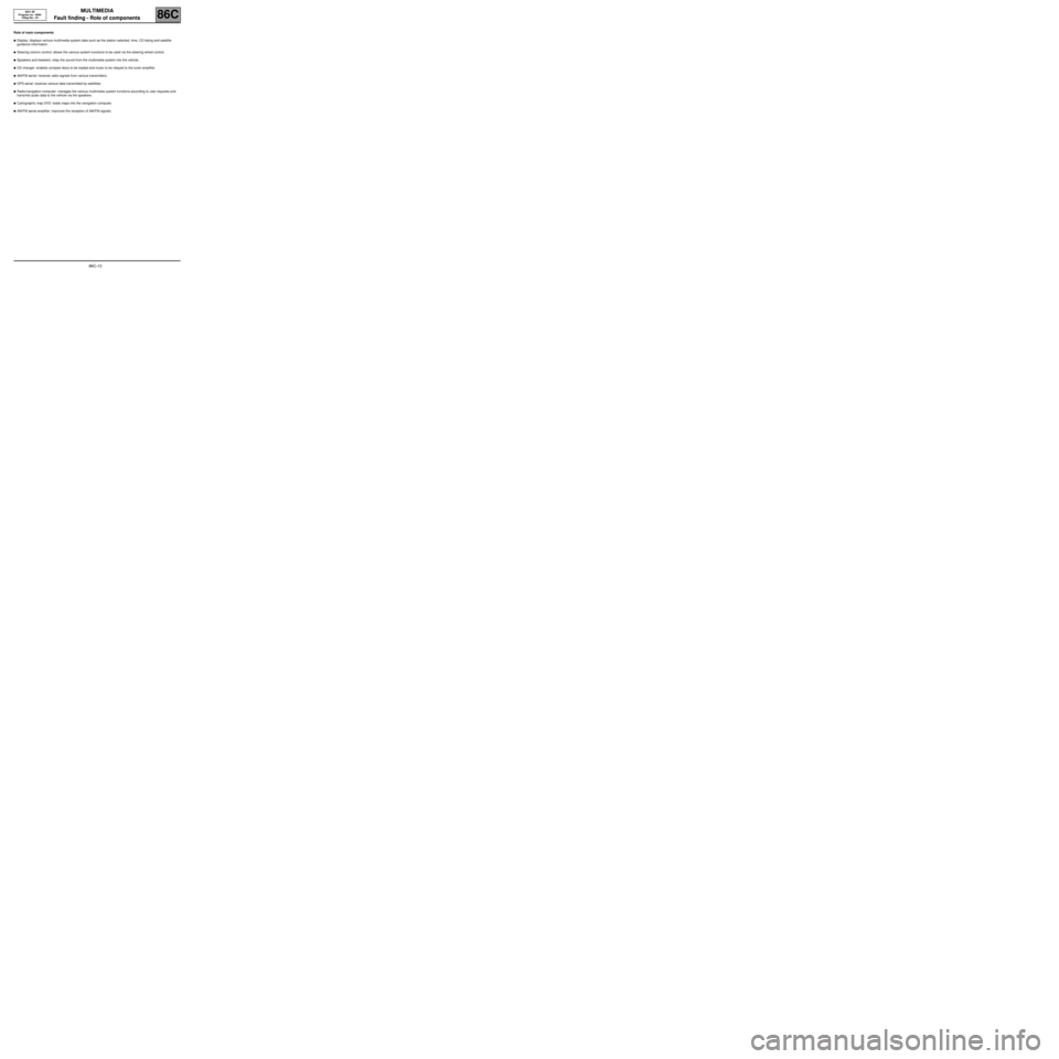
Fault finding - Role of components
Role of main components
â—ŹDisplay: displays various multimedia system data such as the station selected, time, CD listing and satellite
guidance information.
â—ŹSteering column control: allows the various system functions to be used via the steering wheel control.
â—ŹSpeakers and tweeters: relay the sound from the multimedia system into the vehicle.
â—ŹCD changer: enables compact discs to be loaded and music to be relayed to the tuner-amplifier.
â—ŹAM/FM aerial: receives radio signals from various transmitters.
â—ŹGPS aerial: receives various data transmitted by satellites.
â—ŹRadio/navigation computer: manages the various multimedia system functions according to user requests and
transmits audio data to the vehicle via the speakers.
â—ŹCartographic map DVD: loads maps into the navigation computer.
â—ŹAM/FM aerial amplifier: improves the reception of AM/FM signals.
Page 15 of 86
MULTIMEDIA
Fault finding - Configuration and programming86C
86C-14
NAV 4R
Program no.: 0000
Vdiag No.: 24
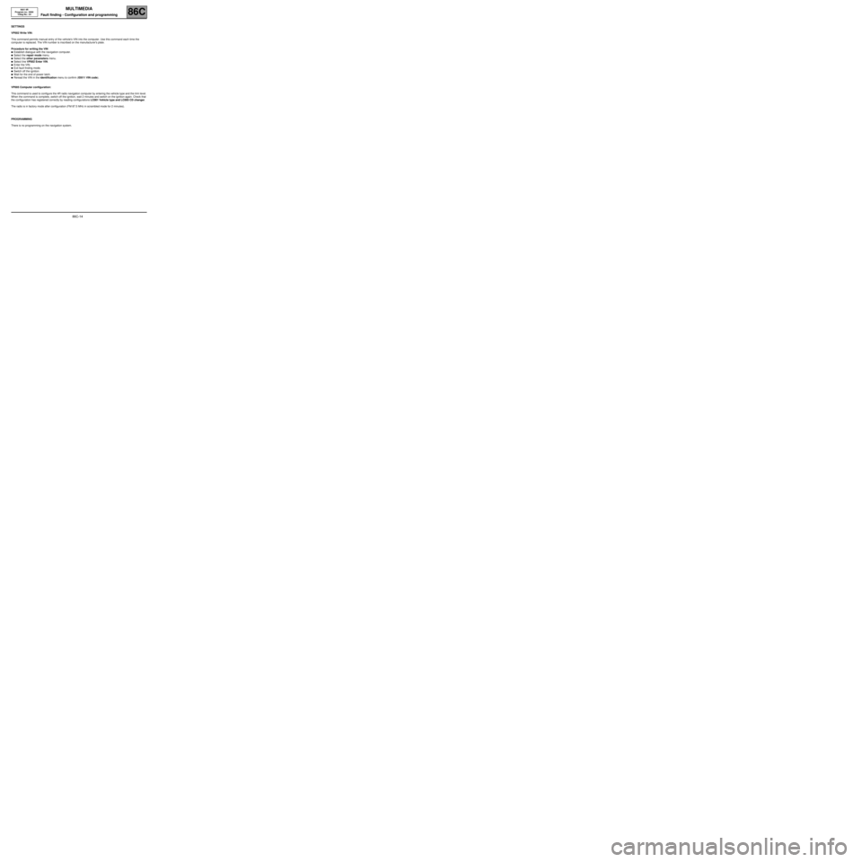
Fault finding - Configuration and programming
SETTINGS
VP002 Write VIN:
This command permits manual entry of the vehicle's VIN into the computer. Use this command each time the
computer is replaced. The VIN number is inscribed on the manufacturer's plate.
Procedure for writing the VIN
â—ŹEstablish dialogue with the navigation computer.
â—ŹSelect the repair mode menu.
â—ŹSelect the other parameters menu.
â—ŹSelect line VP002 Enter VIN.
â—ŹEnter the VIN.
â—ŹExit fault finding mode.
â—ŹSwitch off the ignition.
â—ŹWait for the end of power latch.
â—ŹReread the VIN in the identification menu to confirm (ID011 VIN code).
VP005 Computer configuration:
This command is used to configure the 4R radio navigation computer by entering the vehicle type and the trim level.
When the command is complete, switch off the ignition, wait 2 minutes and switch on the ignition again. Check that
the configuration has registered correctly by reading configurations LC001 Vehicle type and LC005 CD changer.
The radio is in factory mode after configuration (FM 87.5 MHz in scrambled mode for 2 minutes).
PROGRAMMING
There is no programming on the navigation system.
Page 17 of 86
MULTIMEDIA
Fault finding - Replacement of components86C
86C-16
NAV 4R
Program no.: 0000
Vdiag No.: 24
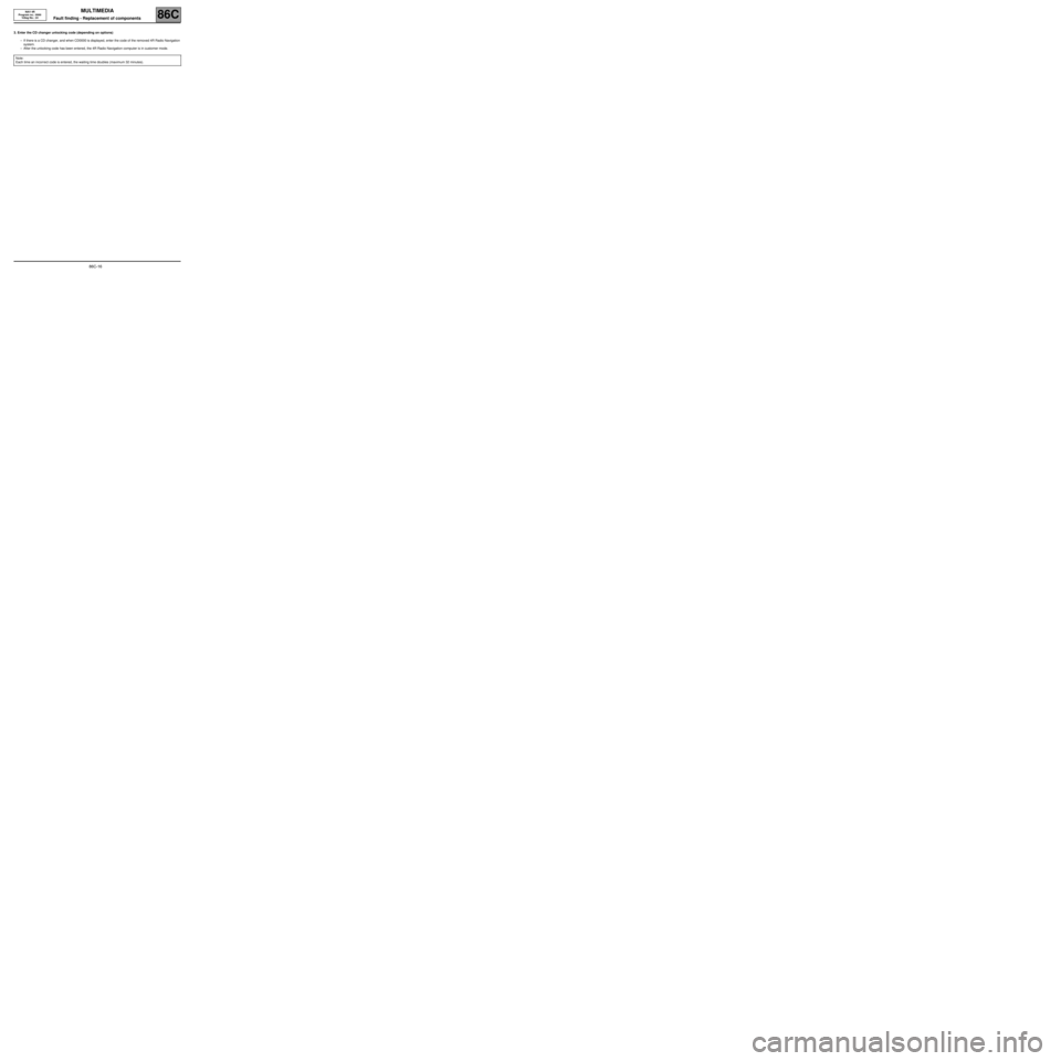
3. Enter the CD changer unlocking code (depending on options)
–If there is a CD changer, and when CD0000 is displayed, enter the code of the removed 4R Radio Navigation
system.
–After the unlocking code has been entered, the 4R Radio Navigation computer is in customer mode.
Note:
Each time an incorrect code is entered, the waiting time doubles (maximum 32 minutes).
Page 18 of 86
MULTIMEDIA
Fault finding - Fault summary table86C
86C-17
NAV 4R
Program no.: 0000
Vdiag No.: 24
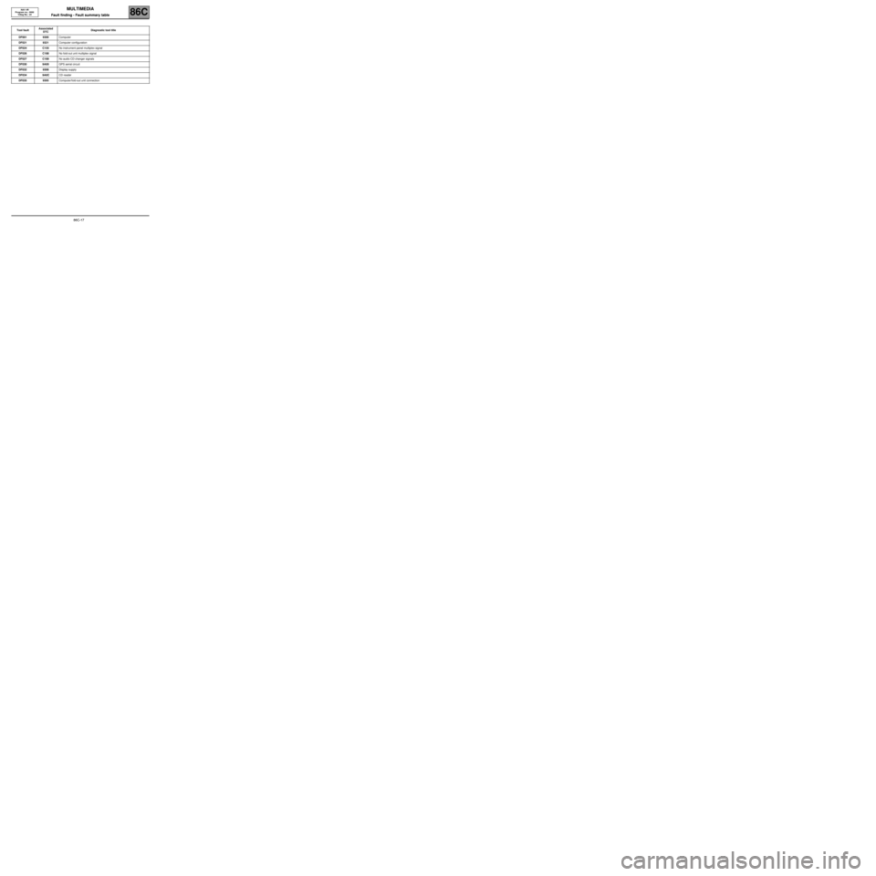
Fault finding - Fault summary table
Tool faultAssociated
DTCDiagnostic tool title
DF001 9300Computer
DF021 9321Computer configuration
DF024 C155No instrument panel multiplex signal
DF026 C188No fold-out unit multiplex signal
DF027 C189No audio CD changer signals
DF030 9A00GPS aerial circuit
DF032 9308Display supply
DF034 9A0CCD reader
DF035 9305Computer/fold-out unit connection