diagram RENAULT SCENIC 2006 J84 / 2.G Multimedia Nav 4R Owner's Manual
[x] Cancel search | Manufacturer: RENAULT, Model Year: 2006, Model line: SCENIC, Model: RENAULT SCENIC 2006 J84 / 2.GPages: 86, PDF Size: 0.29 MB
Page 53 of 86
MULTIMEDIA
Fault finding - Interpretation of parameters86C
86C-52
NAV 4R
Program no.: 0000
Vdiag No.: 24
PR008
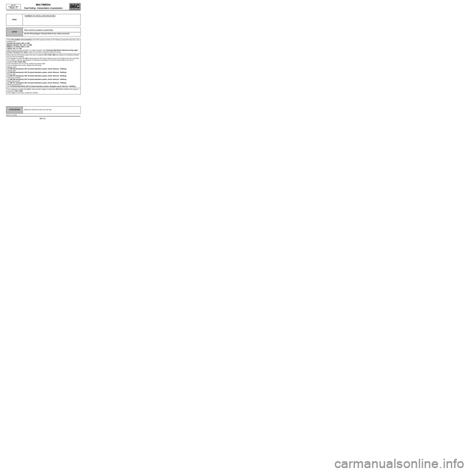
NUMBER OF SATELLITES RECEIVED
NOTESThere must be no present or stored faults.
Use the Wiring Diagram Technical Note for the vehicle concerned.
Check the condition and connection of the GPS coaxial connector of the following components (bent pins, bad
contacts, etc.):
Commercial vehicle: 662 and 886.
Mégane cabriolet: 261, 1551 and 886.
Mégane and Scénic: 886 and 261.
Laguna: 261 and 1551.
If the connector is faulty and there is a repair procedure (see Technical Note 6015A, Electrical wiring repair,
Wiring: Precautions for repair), repair the connector, otherwise replace the wiring.
Disconnect the GPS coaxial cable at the rear of component 261 (Trafic: 662) and measure the resistance between
the core and the shielding.
If the resistance is less than 30 ΩΩ Ω Ω
, disconnect the GPS coaxial cable from the cut-off plate at the rear and check
the insulation, continuity and absence of interference resistance on the GPS coaxial cable at the rear of
component 261 (Trafic: 662).
If the connections are not correct, replace the coaxial cable.
If the connections are correct, replace the GPS aerial.
Mégane II ph2
(see MR 364 mechanical, 83C On-board telematics system, Aerial: Removal - Refitting)
Laguna II ph2
(see MR 395 mechanical, 83C On-board telematics system, Aerial: Removal - Refitting)
Scénic II ph2
(see MR 370 mechanical, 83C On-board telematics system, Aerial: Removal - Refitting)
Trafic II ph1 and ph2
(see MR 408 mechanical, 83C On-board telematics system, Aerial: Removal - Refitting)
Master ph2 and ph3
(see MR 377 mechanical, 83C On-board telematics system, Aerial: Removal - Refitting)
Master propulsion ph2
(see Technical Note 3818A, 83C On-board telematics system, Navigation aerial: Removal - Refitting).
If the resistance is greater than 30 ΩΩ Ω Ω
, check the feed voltage of component 1551 (4.5 V ±± ± ±
0.5 V) at the output of
component 1551 or 886.
If the voltage is not correct, contact the Techline.
AFTER REPAIRRepeat the conformity check from the start.
NAV4R_V24_PR008
Page 55 of 86
MULTIMEDIA
Fault finding - Interpretation of parameters86C
86C-54
NAV 4R
Program no.: 0000
Vdiag No.: 24
PR009
ANGULAR POSITION
NOTESThere must be no present or stored faults.
Engine stopped, ignition on.
Use the Wiring Diagram Technical Note for the vehicle concerned.
Remove component 261 (Trafic: 662) without disconnecting the connectors.
Shake the radio/navigation computer vigorously; parameter PR009 Angular position should be above or equal
to 1 d/s.
Each time the 4R radio/navigation computer is at rest, PR009 Angular position should be very close to 0 d/s.
If the parameter does not change, contact the Techline.
AFTER REPAIRRepeat the conformity check from the start.
NAV4R_V24_PR009
Page 59 of 86
MULTIMEDIA
Fault finding - Dealing with commands
86C
86C-58
NAV 4R
Program no.: 0000
Vdiag No.: 24
AC004
SPEAKER TEST
NOTESThere must be no present or stored faults.
Special note:
A different bleep is emitted from each speaker.
Check that the "balance/fader" settings used are the default ones.
Use the Wiring Diagram Technical Note for the vehicle concerned.
Check the condition and connection of the white 8-track connector of component 261 (Trafic: 662).
Also check the condition and connection of the faulty speaker connector.
If the connector is faulty and there is a repair procedure (see Technical Note 6015A, Electrical wiring repair,
Wiring: Precautions for repair), repair the connector, otherwise replace the wiring.
AFTER REPAIRCarry out another fault finding check on the system.
Page 64 of 86
MULTIMEDIA
Diagnostic - Fault finding chart86C
86C-63
NAV 4R
Program no.: 0000
Vdiag No.: 24
Diagnostic - Fault finding chart
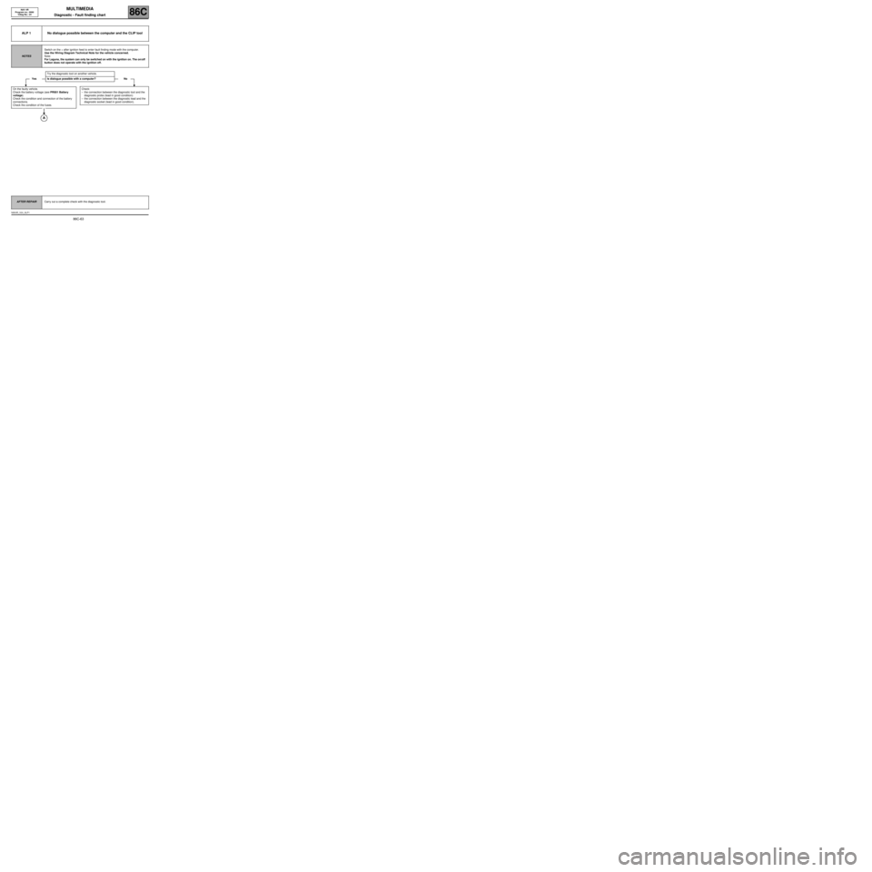
ALP 1 No dialogue possible between the computer and the CLIP tool
NOTESSwitch on the + after ignition feed to enter fault finding mode with the computer.
Use the Wiring Diagram Technical Note for the vehicle concerned.
Note:
For Laguna, the system can only be switched on with the ignition on. The on/off
button does not operate with the ignition off.
Try the diagnostic tool on another vehicle.
Yes Is dialogue possible with a computer? No
On the faulty vehicle.
Check the battery voltage (see PR001 Battery
voltage).
Check the condition and connection of the battery
connections.
Check the condition of the fuses.
Check:
–the connection between the diagnostic tool and the
diagnostic probe (lead in good condition):
–the connection between the diagnostic lead and the
diagnostic socket (lead in good condition).
AFTER REPAIRCarry out a complete check with the diagnostic tool.
NAV4R_V24_ALP1
Page 66 of 86
MULTIMEDIA
Diagnostic - Fault finding chart86C
86C-65
NAV 4R
Program no.: 0000
Vdiag No.: 24
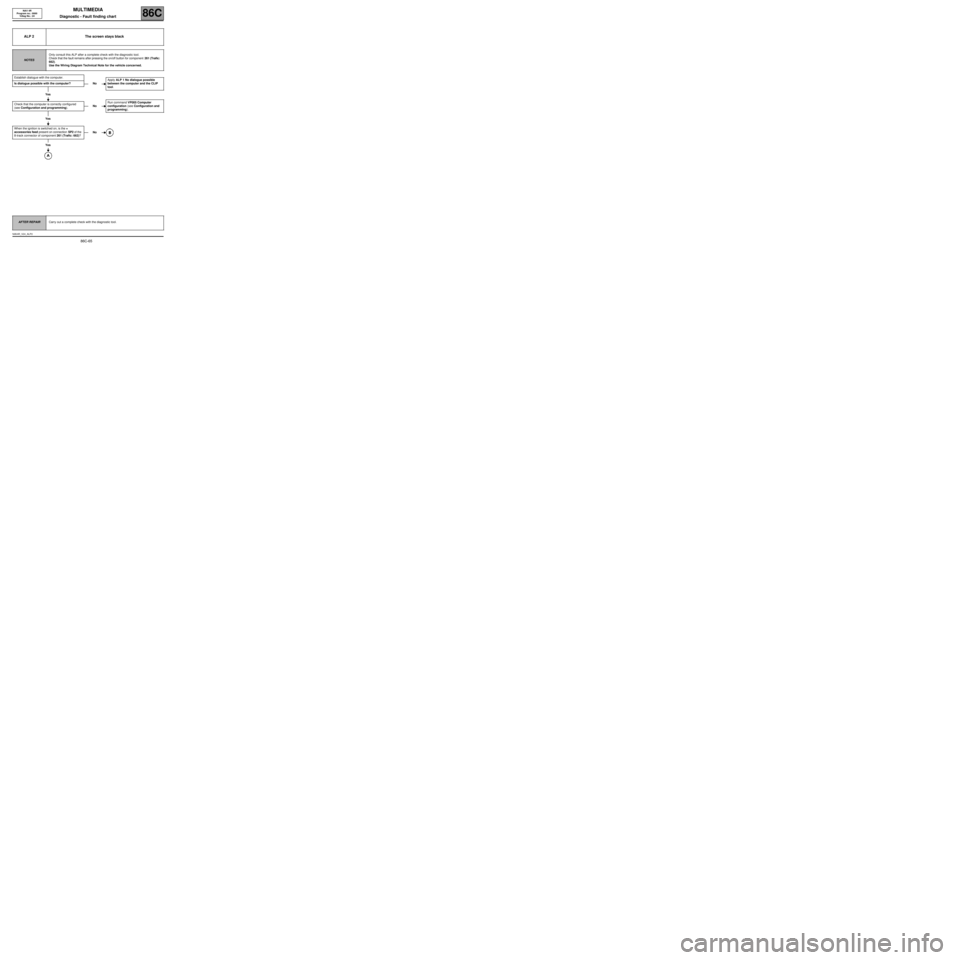
ALP 2 The screen stays black
NOTESOnly consult this ALP after a complete check with the diagnostic tool.
Check that the fault remains after pressing the on/off button for component 261 (Trafic:
662).
Use the Wiring Diagram Technical Note for the vehicle concerned.
Establish dialogue with the computer.
Is dialogue possible with the computer?
Yes
Check that the computer is correctly configured
(see Configuration and programming).
Yes
When the ignition is switched on, is the +
accessories feed present on connection SP2 of the
8-track connector of component 261 (Trafic: 662)?
Yes
NoApply ALP 1 No dialogue possible
between the computer and the CLIP
tool.
NoRun command VP005 Computer
configuration (see Configuration and
programming).
No
AFTER REPAIRCarry out a complete check with the diagnostic tool.
NAV4R_V24_ALP2
Page 68 of 86
MULTIMEDIA
Diagnostic - Fault finding chart86C
86C-67
NAV 4R
Program no.: 0000
Vdiag No.: 24
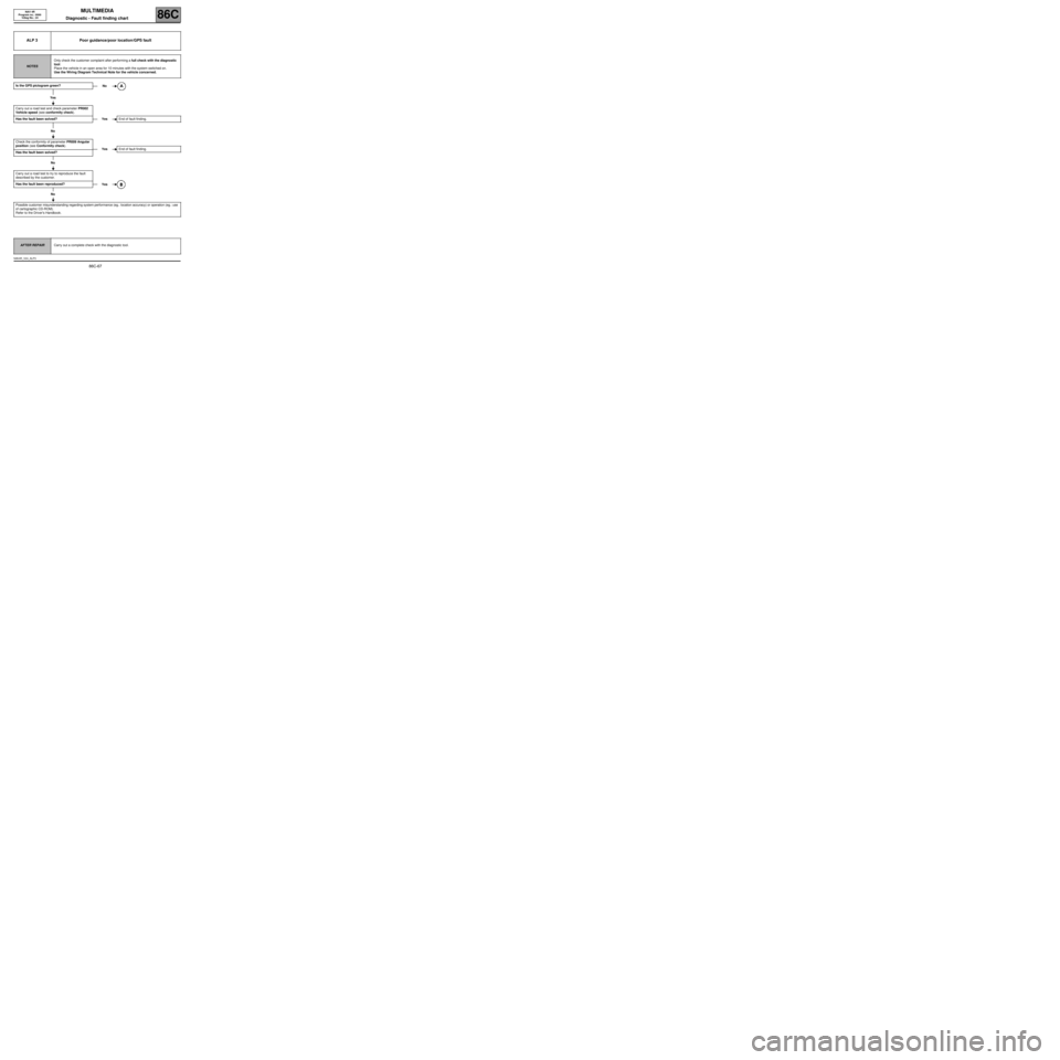
ALP 3 Poor guidance/poor location/GPS fault
NOTESOnly check the customer complaint after performing a full check with the diagnostic
tool.
Place the vehicle in an open area for 10 minutes with the system switched on.
Use the Wiring Diagram Technical Note for the vehicle concerned.
Is the GPS pictogram green?
Yes
Carry out a road test and check parameter PR002
Vehicle speed (see conformity check).
Has the fault been solved?
No
Check the conformity of parameter PR009 Angular
position (see Conformity check).
Has the fault been solved?
No
Carry out a road test to try to reproduce the fault
described by the customer.
Has the fault been reproduced?
No
Possible customer misunderstanding regarding system performance (eg.: location accuracy) or operation (eg.: use
of cartographic CD-ROM).
Refer to the Driver's Handbook.
No
YesEnd of fault finding.
YesEnd of fault finding.
Yes
AFTER REPAIRCarry out a complete check with the diagnostic tool.
NAV4R_V24_ALP3
Page 70 of 86

MULTIMEDIA
Diagnostic - Fault finding chart86C
86C-69
NAV 4R
Program no.: 0000
Vdiag No.: 24
ALP 4 Poor radio reception
NOTESOnly check the customer complaint after performing a full check with the diagnostic
tool.
Use the Wiring Diagram Technical Note for the vehicle concerned.
Is the radio field intensity appropriate (see Interpretation of parameter PR010 Radio field
intensity)?Yes
No
Check the condition and connection of the connectors of component 261 (Trafic: 662) and
component 886.
Using the universal bornier, check the insulation, continuity and the absence of
interference resistance on the following connections:
●TB13 connection code.
●34AN connection code.
Between components 261 (commercial vehicle: 662) and 886.
Also check the feed to component 886 on connection 34AM (12 V ±± ± ±
1 V).
Are the connections faulty?
Yes No
If the connection or connections are faulty and there is a repair procedure
(see Technical Note 6015A, Electrical wiring repair, Wiring:
Precautions for repair), repair the wiring, otherwise replace it.
Has the fault been solved?
Yes No
End of fault finding.
Contact the Techline.
AFTER REPAIRCarry out a complete check with the diagnostic tool.
NAV4R_V24_ALP4
Page 71 of 86

MULTIMEDIA
Diagnostic - Fault finding chart86C
86C-70
NAV 4R
Program no.: 0000
Vdiag No.: 24
ALP 5 CD read fault
NOTESOnly check the customer complaint after performing a full check with the diagnostic
tool.
Ensure there are no present or stored faults.
Use the Wiring Diagram Technical Note for the vehicle concerned.
Is the fault related to CD reading by the radio/
navigation computer or by the 6CD changer?
By the radio/navigation computer By the 6CD changer
Is the CD an MP3 CD?
Yes
Check that component 261 (commercial vehicle:
662) is compatible with MP3 CDs (see "MP3" logo
on keypad).
Yes
Try with another MP3 CD.
Has the fault disappeared?
Yes
The faulty CD is in poor condition or is not
compatible (only MP3 format is compatible).
No
NoEnd of fault finding.
NoContact the Techline.
AFTER REPAIRCarry out a complete check with the diagnostic tool.
NAV4R_V24_ALP5
Page 74 of 86
MULTIMEDIA
Diagnostic - Fault finding chart86C
86C-73
NAV 4R
Program no.: 0000
Vdiag No.: 24
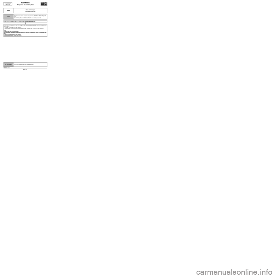
ALP 6Stuck on message
Loading general map
NOTESOnly check the customer complaint after performing a full check with the diagnostic
tool.
Use the Wiring Diagram Technical Note for the vehicle concerned.
Check for the cartographic map CD in component 261 (commercial vehicle: 662).
After inserting the cartographic map CD in component 261 (commercial vehicle: 662), check that the general map
starts loading:
–message "Loading general map" displayed,
–display: (after 1 minute maximum) "progress percentage" pictogram (eg.: 35 %) in the lower status bar.
Note:
Loading may take up to 15 minutes.
Do not interrupt the loading process (by ejecting CD, switching off equipment, cutting + accessories feed,
etc.).
Loading is complete when the map appears.
If the fault is still present, contact the Techline.
AFTER REPAIRCarry out a complete check with the diagnostic tool.
NAV4R_V24_ALP6
Page 76 of 86

MULTIMEDIA
Diagnostic - Fault finding chart86C
86C-75
NAV 4R
Program no.: 0000
Vdiag No.: 24
ALP 8The radio does not switch on automatically
or switches off after 20 minutes
NOTESOnly check the customer complaint after performing a full check with the diagnostic
tool.
Ensure there are no present or stored faults.
Do not apply the following fault finding procedure to the Laguna II ph2.
Use the Wiring Diagram Technical Note for the vehicle concerned.
Check the condition of the + 12 V ACC feed fuse of
component 261 (Trafic: 662).
To obtain the fuse value, see Wiring Diagrams
Technical Note or the value indicated on the fuse
box.
Does the radio come on?
No
Check for + accessories feed. To do this, refer to
the interpretation of status ET002 + 12 V
accessories feed.
Has the fault been solved?
No
Contact the Techline.
YesEnd of fault finding.
Yes
AFTER REPAIRCarry out a complete check with the diagnostic tool.
NAV4R_V24_ALP8