change time RENAULT SCENIC 2008 J84 / 2.G Electrical Equipment - Network Interface Unit Workshop Manual
[x] Cancel search | Manufacturer: RENAULT, Model Year: 2008, Model line: SCENIC, Model: RENAULT SCENIC 2008 J84 / 2.GPages: 46, PDF Size: 0.17 MB
Page 1 of 46
8Electrical equipment
V2 MR-372-J84-86D000$TOC.mif
V2
86D
"The repair procedures given by the manufacturer in this document are based on the
technical specifications current when it was prepared.
The procedures may be modified as a result of changes introduced by the
manufacturer in the production of the various component units and accessories from
which his vehicles are constructed."
V2
All rights reserved by Renault s.a.s.
Edition Anglaise
Copying or translating, in part or in full, of this document or use of the service part
reference numbering system is forbidden without the prior written authority of
Renault s.a.s.
© Renault s.a.s. 2008
MULTIMEDIA NETWORK INTERFACE UNIT
Multimedia Network
interface unit
Vdiag No.: 04, 14
Fault finding - Introduction 86D - 2
Fault finding - List and location of components 86D - 8
Fault finding - Role of components 86D - 9
Fault finding - Operating diagram 86D - 10
Fault finding - Function 86D - 11
Fault finding - Configurations and programming 86D - 12
Fault finding - Replacement of components 86D - 13
Fault finding - Fault summary table 86D - 14
Fault finding - Interpretation of faults 86D - 15
Fault finding - Conformity check 86D - 20
Fault finding - Status summary table 86D - 24
Fault finding - Interpretation of statuses 86D - 25
Fault finding - Parameter summary table 86D - 31
Fault finding - Interpretation of parameters 86D - 32
Fault finding - Command summary table 86D - 36
Fault finding - Customer complaints 86D - 37
Fault finding - Fault Finding Chart 86D - 38
Page 6 of 46
86D-6
MR-372-J84-86D000$056.mif
V2
MULTIMEDIA NETWORK INTERFACE UNIT
Fault finding - Introduction
Multimedia network
interface unit
Vdiag No.: 04, 14
86D
4. FAULT FINDING PROCEDURE (continued)
Wiring check
Fault finding problems
Disconnecting the connectors and/or handling the wiring harness may temporarily remove, the cause of a fault.
Electrical measurements of voltage, resistance and insulation are generally correct, especially if the fault is not
present when the analysis is made (stored fault).
Visual inspection
Look for damage under the bonnet and in the passenger compartment.
Carefully check the fuses, insulators and wiring harness routing.
Look for signs of oxidation.
Physical inspection
While manipulating the wiring, use the diagnostic tool to note any change in fault status from stored to present.
Make sure that the connectors are properly locked.
Apply light pressure to the connectors.
Twist the wiring harness.
If there is a change in status, try to locate the source of the fault.
Inspection of each component
Disconnect the connectors and check the appearance of the clips and tabs, as well as the crimping (no crimping on
the insulating section).
Make sure that the clips and tabs are properly locked in the sockets.
Check that no clips or tabs have been dislodged during connection.
Check the clip contact pressure using an appropriate model of tab.
Resistance check
Check the continuity of entire lines, then section by section.
Look for a short circuit to earth, to + 12 V or to another wire.
If a fault is detected, repair or replace the wiring harness.
Page 9 of 46
86D-9
MR-372-J84-86D000$168.mif
V2
86D
MULTIMEDIA NETWORK INTERFACE UNIT
Fault finding - Role of components
Role of main components
–Display: displays various multimedia system data such as the station selected, time, CD listing and satellite
guidance information.
–Steering column control: allows the various system functions to be used via the steering wheel control.
–Speakers and tweeters: relay the sound from the multimedia system into the vehicle.
–CD changer: enables compact discs to be loaded and music to be relayed to the receiver.
–AM/FM aerial: receives radio signals from various transmitters.
–GPS aerial: receives various data transmitted by satellites.
–Radio/navigation computer: manages the various multimedia system functions according to user requests and
transmits audio data to the vehicle via the speakers.
–Cartographic map DVD: loads maps into the navigation computer.
–AM/FM aerial amplifier: improves the reception of AM/FM signals.
–Multimedia network interface unit: enables information to be exchanged between the “vehicle” and “multimedia”
multiplex networks. This computer is involved in activating the multimedia system.
Multimedia network
interface unit
Vdiag No: 04, 14
MR-372-J84-86D000$168.mif
Page 10 of 46
86D-10
MR-372-J84-86D000$224.mif
V2
86D
MULTIMEDIA NETWORK INTERFACE UNIT
Fault finding - Operating diagram
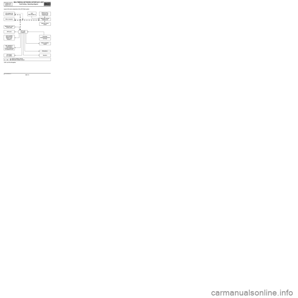
Layout of the main components of the LPN* Radio system:
*LPN: Low Price NavigationV M multiplex line
diagnostic socketUCH
FEED (Kangoo 2)Electric mirror,
passenger side
(Trafic II ph2)
Other computersMultimedia network
interface unit
Steering column
control
Multifunction aerial
(Trafic II ph2)
GPS aerialLPN* radio
navigation
Aerial amplifier
(Espace IV ph2,
Scénic II ph2,
Kangoo 2)Passenger
compartment fuse box
and relay
Radio navigation
display
ABS, ABS/ESP or
wheel speed
computer depending
on equipment level
Microphone
CD changer
(if an option)Speakers
Vehicle multiplex network
Multimedia multiplex network
Multimedia network
interface unit
Vdiag No: 04, 14
MR-372-J84-86D000$224.mif
Page 11 of 46

86D-11
MR-372-J84-86D000$280.mif
V2
86D
MULTIMEDIA NETWORK INTERFACE UNIT
Fault finding - Function
General operation
The multimedia system is involved in the following functions:
–Radio reception (AM, FM).
–Playing CDs/MP3 CDs/navigation map.
–Guidance and navigation system with colour screen.
–Bluetooth hands-free phone.
The use of this multimedia system allows the customer:
–To select radio stations by using the preselections, the list or manual selection.
–To have an automatically-updated radio list.
–To listen to CDs or MP3 CDs.
–To control the radio using the steering column switch (satellite).
–To change various acoustic parameters (bass, treble, fader, etc.).
–To navigate on a colour screen (visual and audio guidance): for this function the system uses GPS, the vehicle
speed wire information and an internal gyroscope.
–To receive traffic information via RDS-TMC and to display it on the navigation map.
Possibility of re-routing according to traffic information.
–To display the time and temperature on the screen.
–To use the hands-free phone function (sound relayed to the radio speakers) with a Bluetooth phone (HFP
profile).
–To be protected by an immobiliser code.
Multimedia network
interface unit
Vdiag No: 04, 14
MR-372-J84-86D000$280.mif
Page 18 of 46
86D-18
MR-372-J84-86D000$504.mif
V2
MULTIMEDIA NETWORK INTERFACE UNIT
Fault finding - Interpretation of faults
Multimedia network
interface unit
Vdiag No: 04, 14
86D
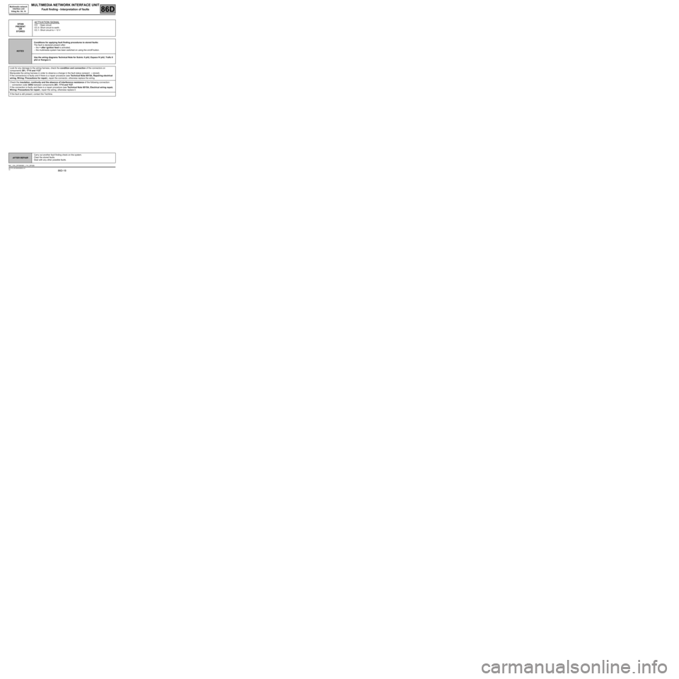
DF006
PRESENT
OR
STOREDACTIVATION SIGNAL
CO : Open circuit
CC.0: Short circuit to earth.
CC.1: Short circuit to + 12 V
NOTESConditions for applying fault finding procedures to stored faults:
The fault is declared present after:
–the + after ignition feed is activated,
–the multimedia system has been switched on using the on/off button.
Use the wiring diagrams Technical Note for Scénic II ph2, Espace IV ph2, Trafic II
ph2 or Kangoo 2.
Look for any damage to the wiring harness, check the condition and connection of the connectors on
components 261, 1714 and 1127.
Manipulate the wiring harness in order to observe a change in the fault status (present → stored).
If the connector(s) is faulty and if there is a repair procedure (see Technical Note 6015A, Repairing electrical
wiring, W iring: Precautions for repair), repair the connector, otherwise replace the wiring.
Check the insulation, continuity and the absence of interference resistance of the following connection:
–connection code 34HU between components 261, 1714 and 1127.
If the connection is faulty and there is a repair procedure (see Technical Note 6015A, Electrical wiring repair,
Wiring: Precautions for repair), repair the wiring, otherwise replace it.
If the fault is still present, contact the Techline.
AFTER REPAIRCarry out another fault finding check on the system.
Clear the stored faults.
Deal with any other possible faults.
BIC_V04_DF006/BIC_V14_DF006