boot RENAULT SCENIC 2008 J84 / 2.G Passenger Comparment Connection Unit User Guide
[x] Cancel search | Manufacturer: RENAULT, Model Year: 2008, Model line: SCENIC, Model: RENAULT SCENIC 2008 J84 / 2.GPages: 391
Page 28 of 391
PASSENGER COMPARTMENT CONNECTION UNIT
Fault finding - System operation
87B
87B-28
PASSENGER COMPARTMENT CONNECTION UNIT
Fault finding - System operation
87B
87B-28V9 MR-372-J84-87B000$086.mif
UCH
Vdiag No.: 44, 48,
4C, 4D, 4F, 50
1.3 SUB-FUNCTION: STARTING
The UCH manages the control section of the starting sub-function. For this function to operate normally, the
protection function must proceed correctly (immobiliser inactive ET046 Immobiliser).
In order to control the starter motor, the UCH requires the following status and parameter information to check that
the starting conditions have been met:
–Start button ET070 Start button.
–Clutch pedal position ET048 Clutch pedal position.
–Brake pedal position ET047 Brake pedal position.
–Automatic gearbox selector lever position ET108 Automatic gearbox selector lever position.
–Position of the manual gearbox selector lever (see 87G, Engine compartment connection unit, Conformity
check).
If the starting conditions are met, the request for the Protection and Switching Unit to activate the starter motor can
be viewed using status ET110 UCH request to injection or Protection and Switching Unit.
1.4 Main COMPONENTS of the ACCESS/SAFETY function
1.4.1 Main components of the ACCESS sub-function:
–Renault card,
–UCH,
–optical presence sensors located in the door handles,
–access aerials integrated in the door handles and the tailgate,
–the locking switches incorporated in the door handles,
–the boot-only opening/locking switch built into the boot badge,
–opening element locking motors.
1.4.1.1 The Renault card:
The Renault card has three buttons which allow:
–locking of the vehicle,
–unlocking of the vehicle,
–the boot to be locked/unlocked.
The Renault hands-free card allows hands-free operation if it is located in the access and starting zones.
The Renault card is powered by a 3 V battery. This battery is required for operation in hands-free mode or remote
control mode (card button presses).
If the battery is old or in an area of frequency interference, the emergency insert located in the Renault card allows
the driver's door to be unlocked.
Page 30 of 391
PASSENGER COMPARTMENT CONNECTION UNIT
Fault finding - System operation
87B
87B-30
PASSENGER COMPARTMENT CONNECTION UNIT
Fault finding - System operation
87B
87B-30V9 MR-372-J84-87B000$086.mif
UCH
Vdiag No.: 44, 48,
4C, 4D, 4F, 50
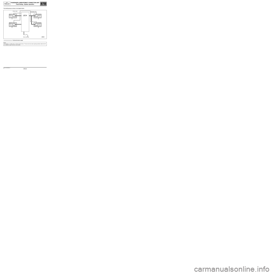
The handle groups are shown in the diagram below:
Communal sensor supply
Note:
The tailgate is not fitted with an infrared optical sensor. The boot and rear screen opening switches notify the UCH
of a request to open the boot or rear screen.
Optical
sensor
+
SwitchDriver's side
Passenger side
Optical
sensor
+
Switch
Optical
sensor
+
SwitchOptical
sensor
+
Switch
Boot unlocking
Page 31 of 391
PASSENGER COMPARTMENT CONNECTION UNIT
Fault finding - System operation
87B
87B-31
PASSENGER COMPARTMENT CONNECTION UNIT
Fault finding - System operation
87B
87B-31V9 MR-372-J84-87B000$086.mif
UCH
Vdiag No.: 44, 48,
4C, 4D, 4F, 50
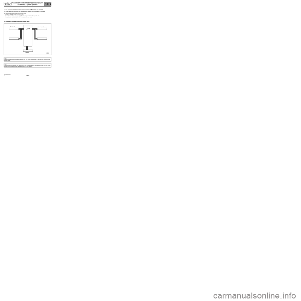
1.4.1.4 The access aerials built into the door handles and tailgate (hands-free vehicles):
The access aerials are built into the door handles and the tailgate. Only the boot aerial is removable.
The UCH activates these aerials in the following order:
–the side on which the handle has been pulled,
–if the card has not been detected, the UCH activates the aerials on the opposite side,
–if the card is still not detected, the UCH interrogates the rear aerial.
The access aerial groups are shown in the diagram below:
Note:
5-door versions manufactured before January 2007 and 3-door versions differ in that they have different handle
access aerials.
Note:
5-door versions manufactured after January 2007 have no access aerials in the rear door handles and have access
aerials in the front door handles identical to those in 3-door versions.
Driver's side
Passenger side
Tailgate
Page 32 of 391
PASSENGER COMPARTMENT CONNECTION UNIT
Fault finding - System operation
87B
87B-32
PASSENGER COMPARTMENT CONNECTION UNIT
Fault finding - System operation
87B
87B-32V9 MR-372-J84-87B000$086.mif
UCH
Vdiag No.: 44, 48,
4C, 4D, 4F, 50
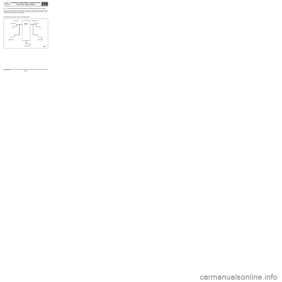
1.4.1.5 The locking switches built into the door handles and the tailgate badge (hands-free vehicles):
These switches are used to lock the opening elements. They are not removable, except for the tailgate switch which
is separate from the badge. When a switch is pressed, a UCH track is connected to earth, informing it of a vehicle
locking request. The access aerials are then activated.
The grouping of these switches is shown in the diagram below:
Driver's side Passenger side
Locking switch Locking switch
Locking switch Locking switch
Boot lid switch
Page 34 of 391
PASSENGER COMPARTMENT CONNECTION UNIT
Fault finding - System operation
87B
87B-34
PASSENGER COMPARTMENT CONNECTION UNIT
Fault finding - System operation
87B
87B-34V9 MR-372-J84-87B000$086.mif
UCH
Vdiag No.: 44, 48,
4C, 4D, 4F, 50
1.4.2.3 The electric steering column lock:
The electric steering column lock is controlled by the UCH. The steering column lock works by inserting and
removing a lock bolt. It replaces the Neimann type lock.
The steering column lock is powered outside + after ignition feed. The steering column lock supply is via the after
ignition relay (located in the Protection and Switching Unit) in its rest position, from where it is distributed to the
column lock by the UCH.
The UCH sends an unlocking request and a code to the steering column lock, via the vehicle's multiplex network.
The multiplex network unlocks the steering column lock if the code is recognised.
A sensor located on the column lock bolt informs the UCH, via the multiplex network and by wire connection, that it
is unlocked.
When unlocking is confirmed, the UCH activates the + after ignition feed via the Protection and Switching Unit. The
column lock is no longer supplied.
The column lock has a "+ after ignition feed present on vehicle" wire signal which inhibits locking while the feed is
active.
1.4.2.4 The injection computer:
The injection computer is coded and unlocks following the encrypted challenge exchange with the UCH.
1.4.2.5 The starting aerials (hands-free vehicles):
There are 3 transmitter aerials located in the passenger compartment. They are controlled by the UCH to interrogate
the card during a starting request or in confirming the presence of the card in the vehicle (e.g. after a door is
opened).
The power used allows the whole passenger compartment to be covered, including the boot. Overspill outside the
passenger compartment is minimal.
1.4.2.6 The card reader:
The card reader is connected to the UCH by a wire connection. It provides the transponder function (like a key
recognition ring). It therefore allows authentication of a Renault card without a battery.
If the card is not detected or recognised during hands-free starting, the card reader flashes to tell the customer to
insert the Renault card.IMPORTANT IMPORTANT
The steering column lock is:
–not removable when the bolt is disengaged,
–fitted with a left-hand thread self-shearing mounting bolt.
Page 105 of 391
PASSENGER COMPARTMENT CONNECTION UNIT
Fault finding - Interpretation of faults
87B
87B -105
PASSENGER COMPARTMENT CONNECTION UNIT
Fault finding - Interpretation of faults
87B
87B -105V9 MR-372-J84-87B000$344.mif
UCH
Vdiag No.: 44, 48,
4C, 4D, 4F, 50
DF032
PRESENT
OR
STOREDBOOT EXTERNAL AERIAL
CO.1: Short circuit or open circuit to + 12 V
NOTESConditions for applying the fault finding procedure to a stored fault:
Activation of command AC037: Transmitter aerial fault finding; if the fault becomes
present, then carry out this fault finding procedure.
Use Wiring Diagrams Technical Note for MEGANE II or SCENIC II.
Check the condition and connection of the external boot aerial connector (tabs bent, broken, etc.).
If the connector is faulty and if there is a repair method (see Technical Note 6015A, Repairing electrical wiring,
Wiring: Precautions for repair), repair the connector; otherwise, replace the wiring.
Check the condition and connection of the PE3 connector of the UCH (tabs bent, broken, etc.).
If the connector is faulty and if there is a repair method (see Technical Note 6015A, Repairing electrical wiring,
Wiring: Precautions for repair), repair the connector; otherwise, replace the wiring.
Check the insulation and the continuity of the following connections:
●Connection code 26AM,
●Connection code 26AN.
Between components 645 and 1378.
If the connection or connections are faulty and there is a repair procedure (see Technical Note 6015A, Electrical
wiring repair, Wiring: Precautions for repair), repair the wiring, otherwise replace it.
Replace the aerial if necessary.
If the fault is still present, contact the Techline.
AFTER REPAIRCarry out another fault finding check on the system.
Clear the stored faults.
Deal with any other faults.
UCH_V44_DF032 /UCH_V48_DF032/UCH_V4C_DF032/
UCH_V4D_DF03 2/UCH_V4F_DF032/UCH_V50_DF032
Page 120 of 391
PASSENGER COMPARTMENT CONNECTION UNIT
Fault finding - Conformity check
87B
87B -120
PASSENGER COMPARTMENT CONNECTION UNIT
Fault finding - Conformity check
87B
87B -120V9 MR-372-J84-87B000$387.mif
UCH
Vdiag No.: 44, 48,
4C, 4D, 4F, 50
KEYLESS VEHICLE FUNCTION
Sub-function: Access (continued 2)
*CPE: Electric central door locking
SR.*: Sunroof
NOTESOnly carry out this conformity check after a complete check with the diagnostic tool
(fault reading and configuration checks).
Application condition: engine stopped, + after ignition feed present.
Sub-functionParameter or
Status
checked Action Display and Notes Fault finding
AccessET061:Open tailgate
requestPRESENT = Tailgate
opening button pressed.
ABSENT = Button not
pressed.In the event of a fault, refer
to the interpretation of
status ET061.
ET050:Tailgate/BootOPEN
CLOSED In the event of a fault,
consult the interpretation
of status ET050.
ET062:Open rear
screen requestABSENT
PRESENTNone
ET041:Opening rear
screenOPEN
CLOSED None
ET044:CPE* buttonPRESSED
RELEASEDIn the event of a fault,
consult the interpretation
of status ET044.
ET233:Child safety lock
switchPRESSED
RELEASEDIn the event of a fault,
consult the interpretation
of status ET233.
ET230:Child safety lockACTIVE
INACTIVEIn the event of a fault,
consult the interpretation
of fault DF072.
ET160:Rear right-hand
door Child safety
lockACTIVE
INACTIVEIn the event of a fault, refer
to the interpretation of
status ET160.
ET159:Rear left-hand
door child safety
lockACTIVE
INACTIVEIn the event of a fault, refer
to the interpretation of
status ET159.
ET087:One-touch
window control/
SR.*
authorisation ACTIVE
INACTIVEIn the event of a fault, refer
to the interpretation of
status ET087.
Page 140 of 391
PASSENGER COMPARTMENT CONNECTION UNIT
Fault finding - Status summary table
87B
87B -140
PASSENGER COMPARTMENT CONNECTION UNIT
Fault finding - Status summary table
87B
87B -140V9 MR-372-J84-87B000$430.mif
UCH
Vdiag No.: 44, 48,
4C, 4D, 4F, 50
*RAID: Renault Anti-Intruder Device
*CPE: Electric central door locking
*Lckg: Locking Tool status Diagnostic tool title Vdiag
ET041Opening rear screenV48, V4C, V4D,
V4F, V50
ET042Passenger door V44, V48, V4C,
V4D, V4F, V50
ET043RAID* function authorisation by CPE*
V44, V48, V4C,
V4D, V4F, V50 ET044CPE* button
ET045RF signal received
ET046Engine immobiliser
ET047Brake pedal position
ET048Clutch pedal position
ET050Tailgate/Boot
ET051Rear left-hand door
ET052Rear right-hand door
ET053Driver's door
ET054Optical sensors supplied
ET055Front driver side optical sensor
ET056Rear driver side optical sensor
ET057Passenger side front/rear optical sensor
ET058Lckg* button on driver's side handles
ET059Lckg* buttons on passenger's side handles
ET060Tailgate locking button
ET061Open tailgate request
ET062Open rear screen requestV48, V4C, V4D,
V4F, V50
Page 172 of 391
PASSENGER COMPARTMENT CONNECTION UNIT
Fault finding - Interpretation of statuses
87B
87B -172
PASSENGER COMPARTMENT CONNECTION UNIT
Fault finding - Interpretation of statuses
87B
87B -172V9 MR-372-J84-87B000$473.mif
UCH
Vdiag No.: 44, 48,
4C, 4D, 4F, 50
ET050
TAILGATE/BOOT
NOTESThere must be no present or stored faults.
Use Wiring Diagrams Technical Note for MEGANE II or SCENIC II.
Check the condition and connection of the PE1 connector of the UCH (tabs bent, broken, oxidised etc.).
If the connector is faulty and if there is a repair procedure (see Technical Note 6015A, Repairing electrical
wiring, Wiring: Precautions for repair), repair the connector; otherwise, replace the wiring.
Check the condition and connection of the boot lock connector (bent, broken, oxidised tabs, etc.).
If the connector is faulty and if there is a repair procedure (see Technical Note 6015A, Repairing electrical
wiring, Wiring: Precautions for repair), repair the connector; otherwise, replace the wiring.
Check the insulation and continuity of the following connection:
●Connection code 87T between components 645 and 1322.
If the connection is faulty and there is a repair procedure (see Technical Note 6015A, Electrical wiring repair,
wiring: precautions for repair), repair the wiring, otherwise replace it.
Check:
The insulation of component 1332 on connections 87T and MZ (tailgate lock contact in rest position).
The continuity of component 1332 on connections 87T and MZ (tailgate lock contact engaged).
Replace the lock if it is not correct.
If the fault is still present, contact the Techline.
AFTER REPAIRCarry out another fault finding check on the system.
Clear the stored faults.
Deal with any other faults.
UCH_V44_ET050/UCH_V48_ET050/ UCH_V4C_ET050/
UCH_V4D_ET050 /UCH_V4F_ET050/UCH_V50_ET050
Page 180 of 391
PASSENGER COMPARTMENT CONNECTION UNIT
Fault finding - Interpretation of statuses87B
87B - 180
PASSENGER COMPARTMENT CONNECTION UNIT
Fault finding - Interpretation of statuses87B
87B - 180V9 MR-372-J84-87B000$516.mif
UCH
Vdiag No.: 44, 48,
4C, 4D, 4F, 50
ET060
LOCKING BUTTON ON TAILGATE
NOTESThere must be no faults present.
Use Wiring Diagrams Technical Note for MEGANE II or SCENIC II.
Check the condition and connection of the transparent connector of the boot locking button (tabs crushed, broken,
oxidised, etc.).
If the connector is faulty and if there is a repair procedure (see Technical Note 6015A, Repairing electrical
wiring, Wiring: Precautions for repair), repair the connector; otherwise, replace the wiring.
Check the condition and connection of the PE3 connector of the UCH (tabs bent, broken, oxidised etc.).
If the connector is faulty and if there is a repair procedure (see Technical Note 6015A, Repairing electrical
wiring, Wiring: Precautions for repair), repair the connector; otherwise, replace the wiring.
Check for an earth on connection MZ of component 1409.
If the connector is faulty and if there is a repair procedure (see Technical Note 6015A, Repairing electrical
wiring, Wiring: Precautions for repair), repair the connector; otherwise, replace the wiring.
Check the insulation and continuity of the following connection:
●Connection code 26AR between components 645 and 1409.
If the connection is faulty and there is a repair procedure (see Technical Note 6015A, Electrical wiring repair,
Wiring: Precautions for repair), repair the wiring, otherwise replace it.
Check the insulation of the following connections (tailgate button in Released position) and the continuity of the
following connections (tailgate button in Pressed position):
●Connection code 26AR,
●Connection code MZ of component 1409.
Replace the button if necessary.
If the fault is still present, contact Techline.
AFTER REPAIRCarry out another fault finding check on the system.
Clear the stored faults.
Deal with any other faults.
UCH_V44_ET060/UCH_V48_ET060/ UCH_V4C_ET060/
UCH_V4D_ET060 /UCH_V4F_ET060/UCH_V50_ET060