lights RENAULT SCENIC 2008 J84 / 2.G Passenger Comparment Connection Unit Owner's Manual
[x] Cancel search | Manufacturer: RENAULT, Model Year: 2008, Model line: SCENIC, Model: RENAULT SCENIC 2008 J84 / 2.GPages: 391
Page 142 of 391
PASSENGER COMPARTMENT CONNECTION UNIT
Fault finding - Status summary table
87B
87B -142
PASSENGER COMPARTMENT CONNECTION UNIT
Fault finding - Status summary table
87B
87B -142V9 MR-372-J84-87B000$430.mif
UCH
Vdiag No.: 44, 48,
4C, 4D, 4F, 50
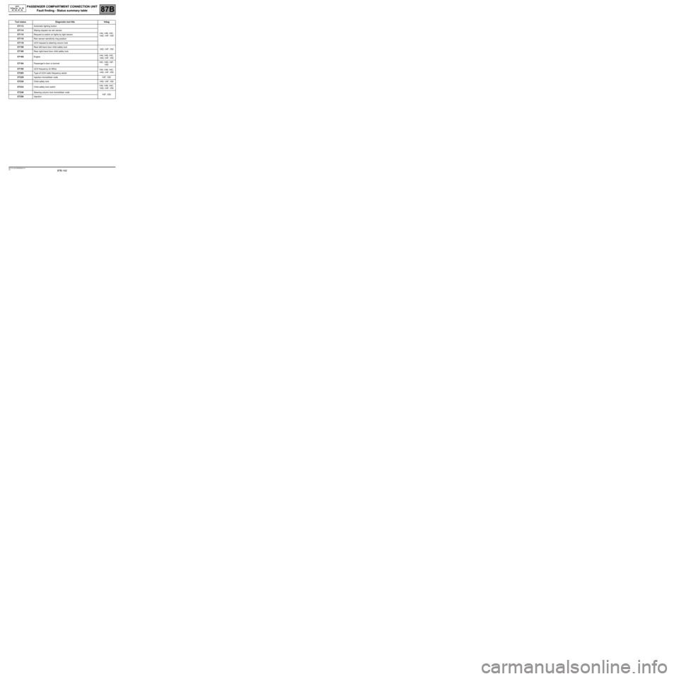
Tool status Diagnostic tool title Vdiag
ET113Automatic lighting button
V44, V48, V4C,
V4D, V4F, V50 ET114Wiping request via rain sensor
ET115Request to switch on lights by light sensor
ET118Rain sensor sensitivity ring position
ET119UCH request to steering column lock
ET159Rear left-hand door child safety lock
V4D, V4F, V50
ET160Rear right-hand door child safety lock
ET169Engine V44, V48, V4C,
V4D, V4F, V50
ET194Passenger's door or bonnet V4C, V4D, V4F,
V50
ET195UCH frequency (in MHz)
V44, V48, V4C,
V4D, V4F, V50
ET205Type of UCH radio frequency aerial
ET229Injection immobiliser code V4F, V50
ET230Child safety lock V4D, V4F, V50
ET233Child safety lock switchV44, V48, V4C,
V4D, V4F, V50
ET248Steering column lock immobiliser code
V4F, V50
ET250Injection
Page 159 of 391
PASSENGER COMPARTMENT CONNECTION UNIT
Fault finding - Interpretation of statuses
87B
87B -159
PASSENGER COMPARTMENT CONNECTION UNIT
Fault finding - Interpretation of statuses
87B
87B -159V9 MR-372-J84-87B000$473.mif
UCH
Vdiag No.: 44, 48,
4C, 4D, 4F, 50
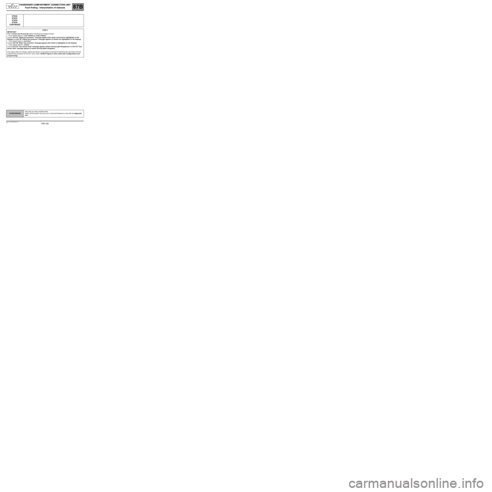
ET032
ET033
ET034
ET035
CONTINUED
STEP 2
IMPORTANT:
Wait 1 minute and 30 seconds before checking the change of status.
–If the original status is: over-inflated or under-inflated
Consult ALP 52 "Adjust tyre pressure" message appears (the wheel concerned is highlighted on the
display) and ALP 56 "Adjust tyre pressure" message appears (2 wheels are highlighted on the display).
–If the original status is: puncture
Consult ALP 56 "Stop! Tyre puncture" message appears (the wheel is highlighted on the display).
–If the original status is: absent
Consult ALP 54 "Tyre sensor fault" message appears (wheel warning light disappears) and ALP 55 "Tyre
sensor fault" message appears (4 wheel warning lights disappear).
If the status does not change, replace the sensor on the wheel concerned by following the instructions and the
programming procedure for the four valve codes, SC002 Program 4 valve codes (see Configurations and
programming).
AFTER REPAIRDeal with any other possible faults.
Switch off the ignition and carry out a road test followed by a test with the diagnostic
tool.
Page 168 of 391
PASSENGER COMPARTMENT CONNECTION UNIT
Fault finding - Interpretation of statuses
87B
87B -168
PASSENGER COMPARTMENT CONNECTION UNIT
Fault finding - Interpretation of statuses
87B
87B -168V9 MR-372-J84-87B000$473.mif
UCH
Vdiag No.: 44, 48,
4C, 4D, 4F, 50
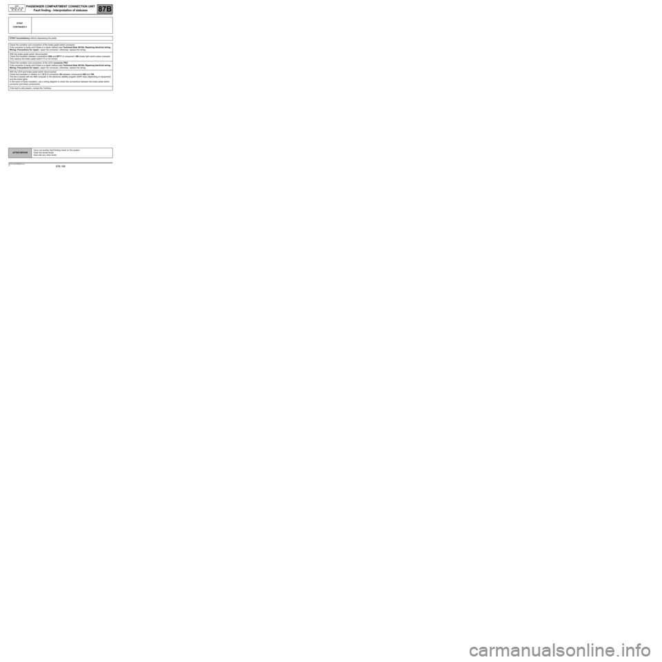
ET047
CONTINUED 2
ET047 Inconsistency without depressing the pedal.
Check the condition and connection of the brake pedal switch connector.
If the connector is faulty and if there is a repair method (see Technical Note 6015A, Repairing electrical wiring,
Wiring: Precautions for repair), repair the connector; otherwise, replace the wiring.
With the brake pedal switch disconnected:
Check the insulation between connections 65A and SP17 of component 160 (brake light switch piston pressed).
Only replace the brake pedal switch if it is not correct.
Check the condition and connection of the UCH connector PE2.
If the connector is faulty and if there is a repair method (see Technical Note 6015A, Repairing electrical wiring,
Wiring: Precautions for repair), repair the connector; otherwise, replace the wiring.
With the UCH and brake pedal switch disconnected:
Check the insulation in relation to + 12 V of connection 5A between components 645 and 160.
The line is shared with the ABS computer or the electronic stability program (ESP) relay (depending on equipment)
and the brake lights.
In the event of faulty insulation, use a wiring diagram to check the connections between the brake pedal switch
connector and these components.
If the fault is still present, contact the Techline.
AFTER REPAIRCarry out another fault finding check on the system.
Clear the stored faults.
Deal with any other faults.
Page 169 of 391
PASSENGER COMPARTMENT CONNECTION UNIT
Fault finding - Interpretation of statuses
87B
87B -169
PASSENGER COMPARTMENT CONNECTION UNIT
Fault finding - Interpretation of statuses
87B
87B -169V9 MR-372-J84-87B000$473.mif
UCH
Vdiag No.: 44, 48,
4C, 4D, 4F, 50
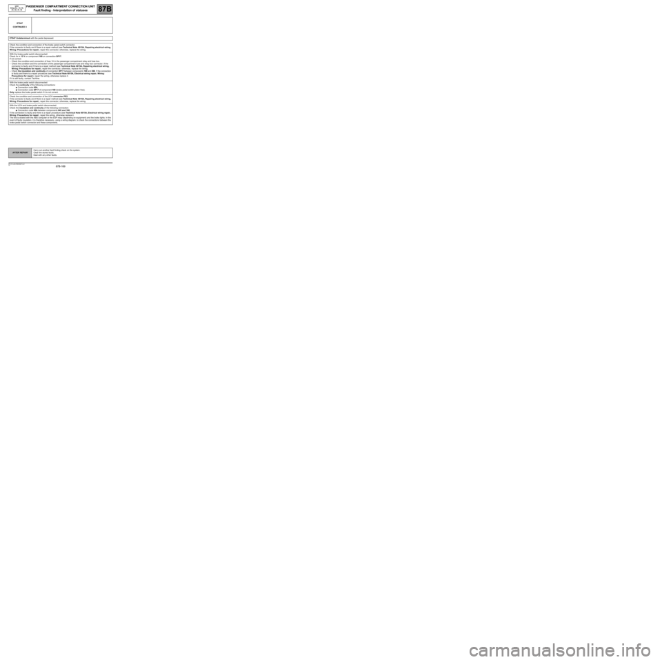
ET047
CONTINUED 3
ET047 Undetermined with the pedal depressed.
Check the condition and connection of the brake pedal switch connector.
If the connector is faulty and if there is a repair method (see Technical Note 6015A, Repairing electrical wiring,
Wiring: Precautions for repair), repair the connector; otherwise, replace the wiring.
With the brake pedal switch disconnected:
Check for + 12 V on component 160 on connection SP17.
If not correct:
–Check the condition and connection of fuse 1H in the passenger compartment relay and fuse box.
–Check the condition and the connection of the passenger compartment fuse and relay box connector. If the
connector is faulty and if there is a repair method (see Technical Note 6015A, Repairing electrical wiring,
Wiring: Precautions for repair), repair the connector; otherwise, replace the wiring.
–Check the insulation and continuity of connection SP17 between components 160 and 260. If the connection
is faulty and there is a repair procedure (see Technical Note 6015A, Electrical wiring repair, Wiring:
Precautions for repair), repair the wiring, otherwise replace it.
If it is still faulty, contact Techline.
With the brake pedal switch disconnected:
Check the continuity of the following connections:
●Connection code 65A,
●Connection code SP17 of component 160 (brake pedal switch piston free).
Only replace the brake pedal switch if it is not correct.
Check the condition and connection of the UCH connector PE2.
If the connector is faulty and if there is a repair method (see Technical Note 6015A, Repairing electrical wiring,
Wiring: Precautions for repair), repair the connector; otherwise, replace the wiring.
With the UCH and brake pedal switch disconnected:
Check the insulation and continuity of the following connection:
●Connection code 65A between components 645 and 160.
If the connection is faulty and there is a repair procedure (see Technical Note 6015A, Electrical wiring repair,
Wiring: Precautions for repair), repair the wiring, otherwise replace it.
The line is shared with the ABS computer or the ESP relay (depending on equipment) and the brake lights. In the
event of faulty insulation, it is therefore necessary, using a wiring diagram, to check the connections between the
brake pedal switch connector and these components.
AFTER REPAIRCarry out another fault finding check on the system.
Clear the stored faults.
Deal with any other faults.
Page 196 of 391
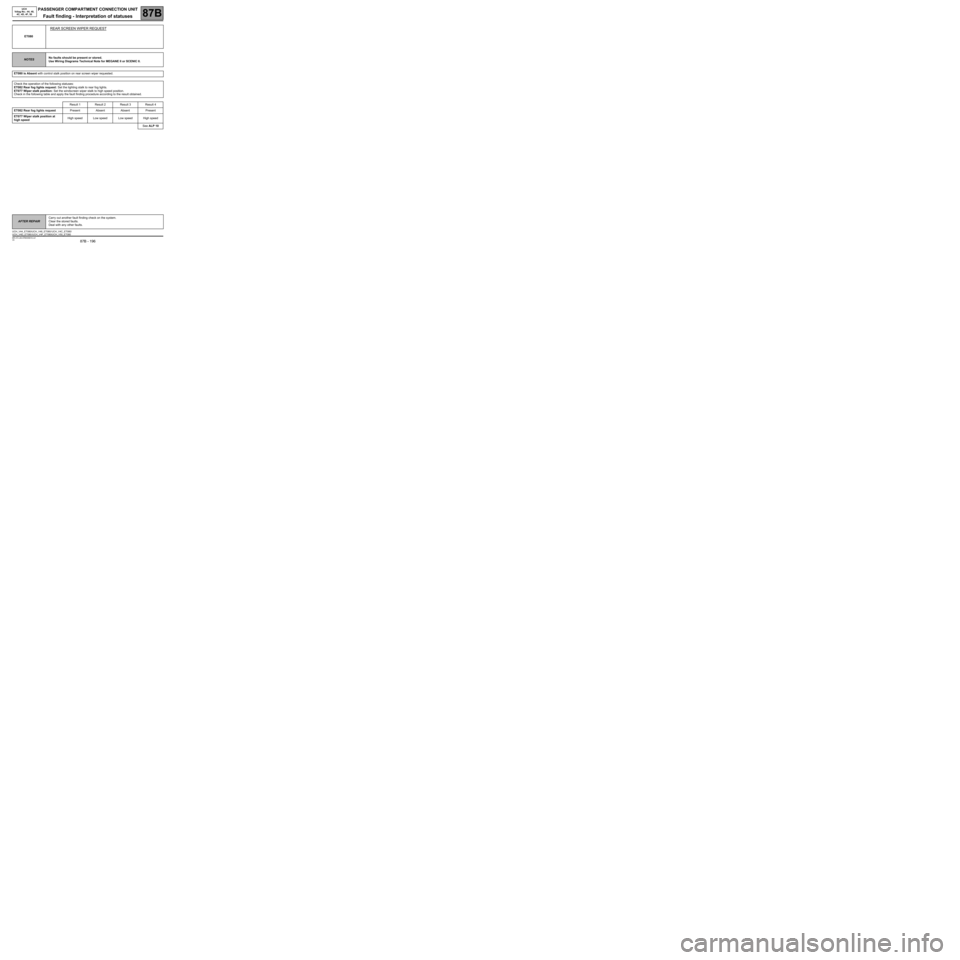
PASSENGER COMPARTMENT CONNECTION UNIT
Fault finding - Interpretation of statuses87B
87B - 196V9 MR-372-J84-87B000$516.mif
UCH
Vdiag No.: 44, 48,
4C, 4D, 4F, 50
ET080
REAR SCREEN WIPER REQUEST
NOTESNo faults should be present or stored.
Use Wiring Diagrams Technical Note for MEGANE II or SCENIC II.
ET080 is Absent with control stalk position on rear screen wiper requested.
Check the operation of the following statuses:
ET082 Rear fog lights request: Set the lighting stalk to rear fog lights.
ET077 Wiper stalk position: Set the windscreen wiper stalk to high speed position.
Check in the following table and apply the fault finding procedure according to the result obtained.
Result 1 Result 2 Result 3 Result 4
ET082 Rear fog lights requestPresent Absent Absent Present
ET077 Wiper stalk position at
high speedHigh speed Low speed Low speed High speed
See ALP 10
AFTER REPAIRCarry out another fault finding check on the system.
Clear the stored faults.
Deal with any other faults.
UCH_V44_ET080/UCH_V48_ET080/ UCH_V4C_ET080/
UCH_V4D_ET080 /UCH_V4F_ET080/UCH_V50_ET080
Page 200 of 391
PASSENGER COMPARTMENT CONNECTION UNIT
Fault finding - Interpretation of statuses87B
87B - 200
PASSENGER COMPARTMENT CONNECTION UNIT
Fault finding - Interpretation of statuses87B
87B - 200V9 MR-372-J84-87B000$516.mif
UCH
Vdiag No.: 44, 48,
4C, 4D, 4F, 50
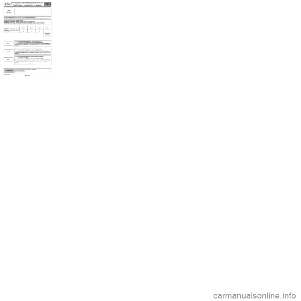
ET081
CONTINUED 2
ET081 is Dipped beam with control stalk position at side lights requested.
Check the operation of the following statuses:
ET080 Rear screen wiper request: Set control stalk to rear screen wiper.
ET096 Windscreen wiper stalk intermittent speed ring position: Set the speed ring to position 1.
Check in the following table and apply the fault finding procedure according to the result obtained.
Result 1 Result 2 Result 3 Result 4
ET080 Rear screen wiper requestPresent Absent Absent Present
ET096 Rear screen wiper speed
ring position4141
Change the
steering
column control
Check the continuity and insulation of the following connection:
●Connection code 141B between components 645 and 1519.
If the connection is faulty and there is a repair procedure (see Technical Note 6015A,
Electrical wiring repair, Wiring: Precautions for repair), repair the wiring, otherwise
replace it.
Check the continuity and insulation of the following connection:
●Connection code 141N between components 645 and 1519.
If the connection is faulty and there is a repair procedure (see Technical Note 6015A,
Electrical wiring repair, Wiring: Precautions for repair), repair the wiring, otherwise
replace it.
Check the continuity and insulation of the following connections:
●Connection code 141L.
●Connection code 141N between components 645 and 1519.
If the connection(s) is faulty and there is a repair procedure (see Technical Note 6015A,
Electrical wiring repair, Wiring: Precautions for repair), repair the wiring, otherwise
replace it.
If the fault is still present, contact the Techline.
Result 1
Result 2
Result 3
AFTER REPAIRCarry out another fault finding check on the system.
Clear the stored faults.
Deal with any other faults.
Page 201 of 391
PASSENGER COMPARTMENT CONNECTION UNIT
Fault finding - Interpretation of statuses87B
87B - 201
PASSENGER COMPARTMENT CONNECTION UNIT
Fault finding - Interpretation of statuses87B
87B - 201V9 MR-372-J84-87B000$516.mif
UCH
Vdiag No.: 44, 48,
4C, 4D, 4F, 50
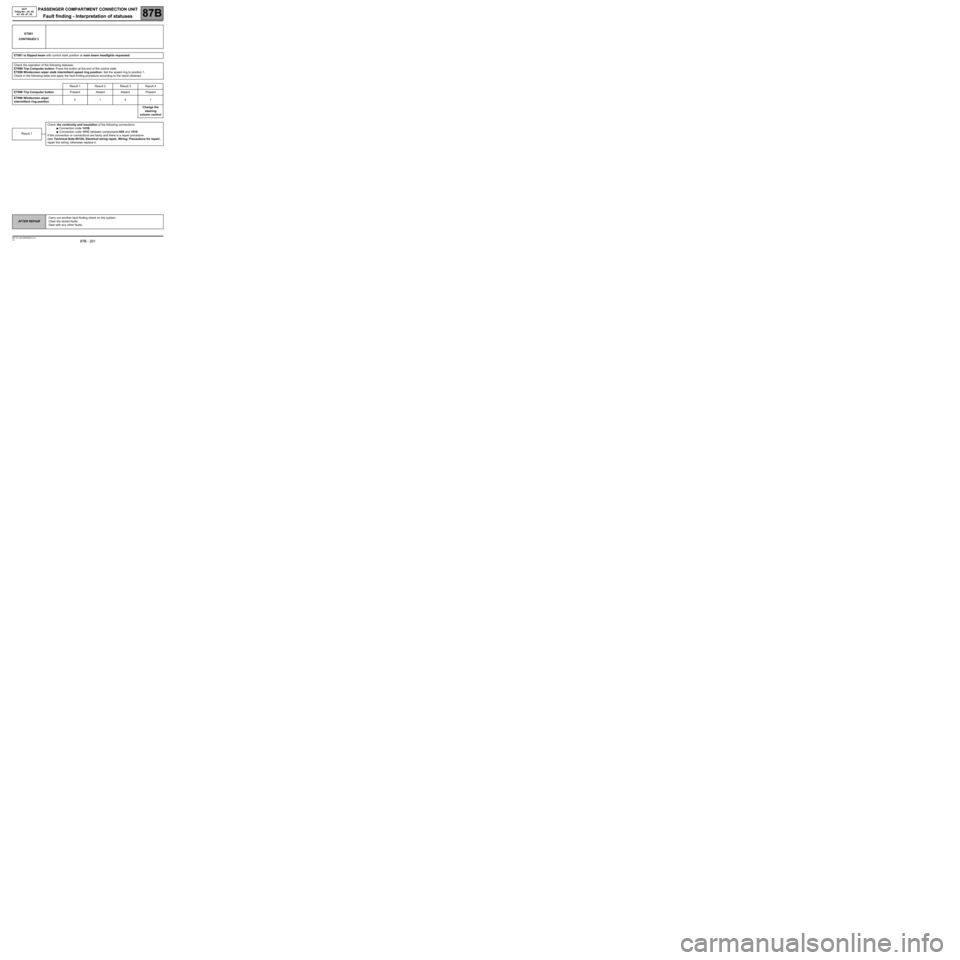
ET081
CONTINUED 3
ET081 is Dipped beam with control stalk position at main beam headlights requested.
Check the operation of the following statuses:
ET098 Trip Computer button: Press the button at the end of the control stalk.
ET096 Windscreen wiper stalk intermittent speed ring position: Set the speed ring to position 1.
Check in the following table and apply the fault finding procedure according to the result obtained.
Result 1 Result 2 Result 3 Result 4
ET098 Trip Computer buttonPresent Absent Absent Present
ET096 Windscreen wiper
intermittent ring position4141
Change the
steering
column control
Check the continuity and insulation of the following connections:
●Connection code 141B.
●Connection code 141C between components 645 and 1519.
If the connection or connections are faulty and there is a repair procedure
(see Technical Note 6015A, Electrical wiring repair, Wiring: Precautions for repair),
repair the wiring, otherwise replace it.Result 1
AFTER REPAIRCarry out another fault finding check on the system.
Clear the stored faults.
Deal with any other faults.
Page 203 of 391
PASSENGER COMPARTMENT CONNECTION UNIT
Fault finding - Interpretation of statuses87B
87B - 203
PASSENGER COMPARTMENT CONNECTION UNIT
Fault finding - Interpretation of statuses87B
87B - 203V9 MR-372-J84-87B000$516.mif
UCH
Vdiag No.: 44, 48,
4C, 4D, 4F, 50
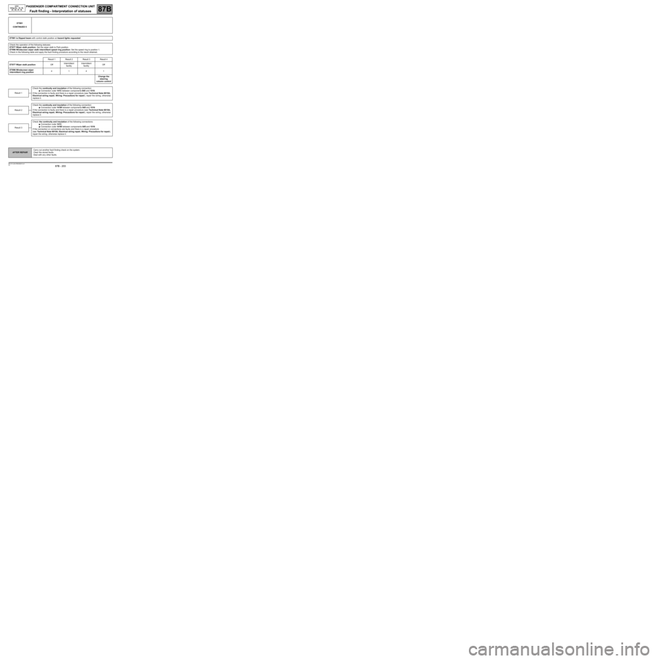
ET081
CONTINUED 5
ET081 is Dipped beam with control stalk position at hazard lights requested.
Check the operation of the following statuses:
ET077 Wiper stalk position: Set the wiper stalk to Park position.
ET096 Windscreen wiper stalk intermittent speed ring position: Set the speed ring to position 1.
Check in the following table and apply the fault finding procedure according to the result obtained.
Result 1 Result 2 Result 3 Result 4
ET077 Wiper stalk positionOffIntermittent
facilityIntermittent
facilityOff
ET096 Windscreen wiper
intermittent ring position4141
Change the
steering
column control
Check the continuity and insulation of the following connection:
●Connection code 141C between components 645 and 1519.
If the connection is faulty and there is a repair procedure (see Technical Note 6015A,
Electrical wiring repair, Wiring: Precautions for repair), repair the wiring, otherwise
replace it.
Check the continuity and insulation of the following connection:
●Connection code 141M between components 645 and 1519.
If the connection is faulty and there is a repair procedure (see Technical Note 6015A,
Electrical wiring repair, Wiring: Precautions for repair), repair the wiring, otherwise
replace it.
Check the continuity and insulation of the following connections:
●Connection code 141C.
●Connection code 141M between components 645 and 1519.
If the connection or connections are faulty and there is a repair procedure
(see Technical Note 6015A, Electrical wiring repair, Wiring: Precautions for repair),
repair the wiring, otherwise replace it.
Result 1
Result 2
Result 3
AFTER REPAIRCarry out another fault finding check on the system.
Clear the stored faults.
Deal with any other faults.
Page 204 of 391
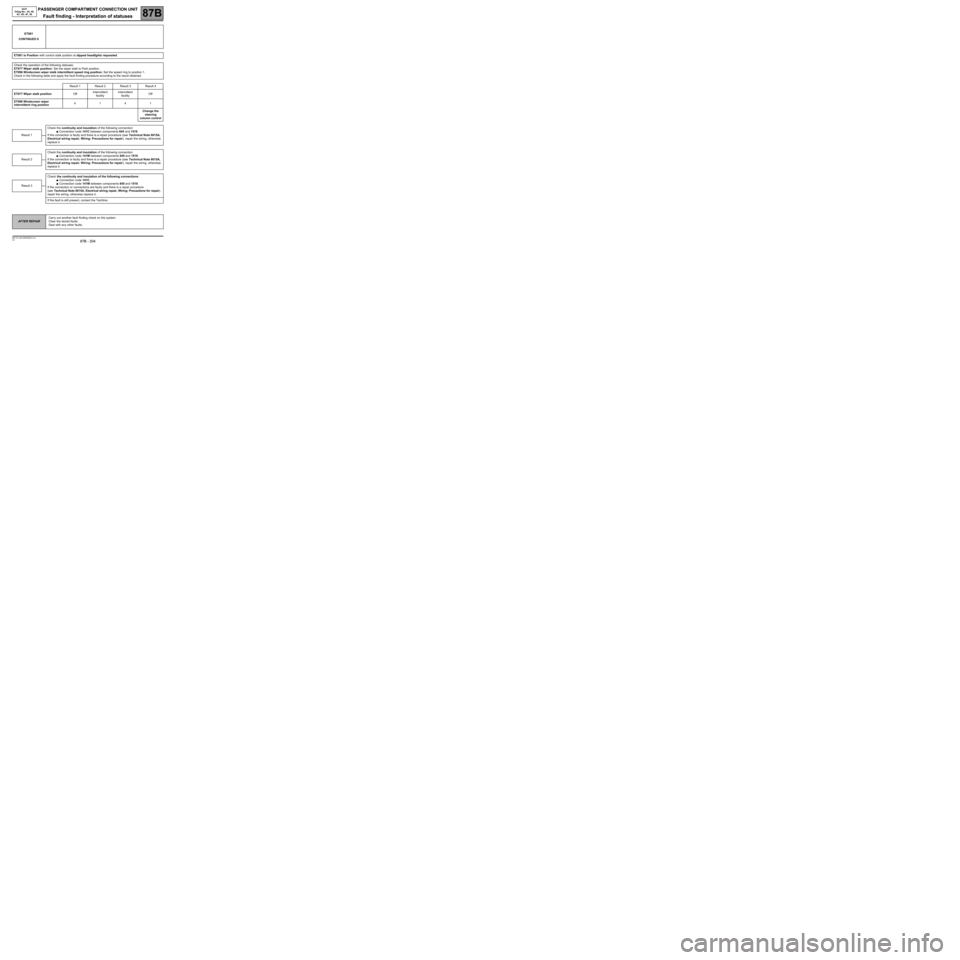
PASSENGER COMPARTMENT CONNECTION UNIT
Fault finding - Interpretation of statuses87B
87B - 204
PASSENGER COMPARTMENT CONNECTION UNIT
Fault finding - Interpretation of statuses87B
87B - 204V9 MR-372-J84-87B000$516.mif
UCH
Vdiag No.: 44, 48,
4C, 4D, 4F, 50
ET081
CONTINUED 6
ET081 is Position with control stalk position at dipped headlights requested.
Check the operation of the following statuses:
ET077 Wiper stalk position: Set the wiper stalk to Park position.
ET096 Windscreen wiper stalk intermittent speed ring position: Set the speed ring to position 1.
Check in the following table and apply the fault finding procedure according to the result obtained.
Result 1 Result 2 Result 3 Result 4
ET077 Wiper stalk positionOffIntermittent
facilityIntermittent
facilityOff
ET096 Windscreen wiper
intermittent ring position4141
Change the
steering
column control
Check the continuity and insulation of the following connection:
●Connection code 141C between components 645 and 1519.
If the connection is faulty and there is a repair procedure (see Technical Note 6015A,
Electrical wiring repair, Wiring: Precautions for repair), repair the wiring, otherwise
replace it.
Check the continuity and insulation of the following connection:
●Connection code 141M between components 645 and 1519.
If the connection is faulty and there is a repair procedure (see Technical Note 6015A,
Electrical wiring repair, Wiring: Precautions for repair), repair the wiring, otherwise
replace it.
Check the continuity and insulation of the following connections:
●Connection code 141C.
●Connection code 141M between components 645 and 1519.
If the connection or connections are faulty and there is a repair procedure
(see Technical Note 6015A, Electrical wiring repair, Wiring: Precautions for repair),
repair the wiring, otherwise replace it.
If the fault is still present, contact the Techline.
Result 1
Result 2
Result 3
AFTER REPAIRCarry out another fault finding check on the system.
Clear the stored faults.
Deal with any other faults.
Page 205 of 391
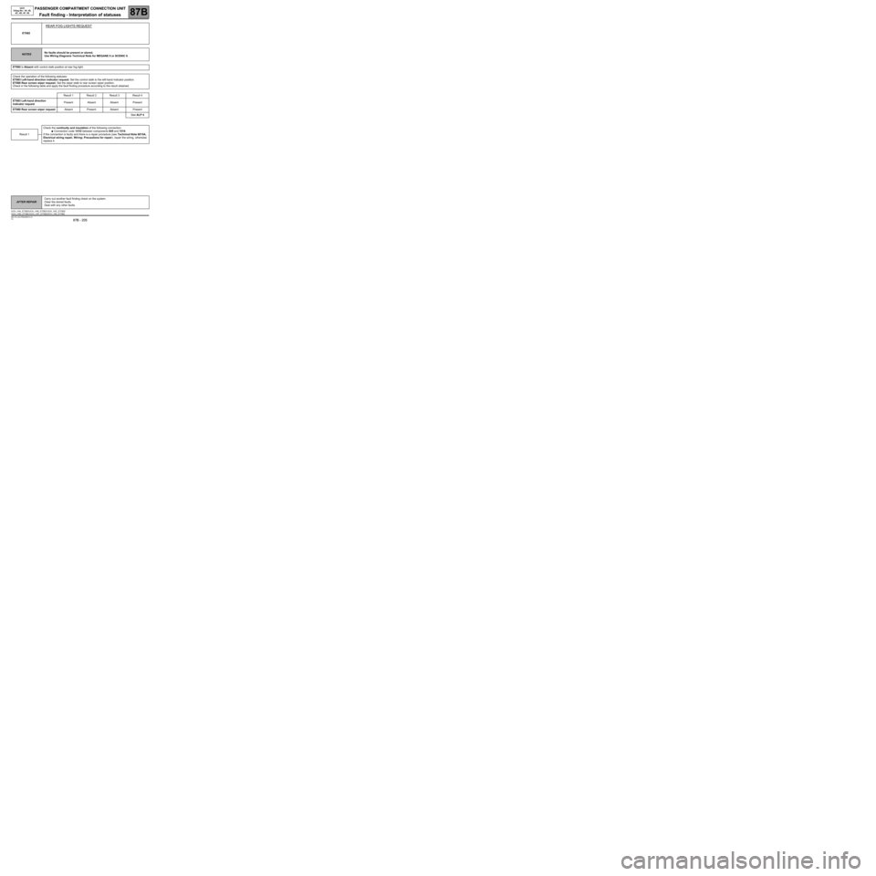
PASSENGER COMPARTMENT CONNECTION UNIT
Fault finding - Interpretation of statuses87B
87B - 205
PASSENGER COMPARTMENT CONNECTION UNIT
Fault finding - Interpretation of statuses87B
87B - 205V9 MR-372-J84-87B000$516.mif
UCH
Vdiag No.: 44, 48,
4C, 4D, 4F, 50
ET082
REAR FOG LIGHTS REQUEST
NOTESNo faults should be present or stored.
Use Wiring Diagrams Technical Note for MEGANE II or SCENIC II.
ET082 is Absent with control stalk position at rear fog light.
Check the operation of the following statuses:
ET083 Left-hand direction indicator request: Set the control stalk to the left-hand indicator position.
ET080 Rear screen wiper request: Set the wiper stalk to rear screen wiper position.
Check in the following table and apply the fault finding procedure according to the result obtained.
Result 1 Result 2 Result 3 Result 4
ET083 Left-hand direction
indicator requestPresent Absent Absent Present
ET080 Rear screen wiper requestAbsent Present Absent Present
See ALP 4
Check the continuity and insulation of the following connection:
●Connection code 141D between components 645 and 1519.
If the connection is faulty and there is a repair procedure (see Technical Note 6015A,
Electrical wiring repair, Wiring: Precautions for repair), repair the wiring, otherwise
replace it.
Result 1
AFTER REPAIRCarry out another fault finding check on the system.
Clear the stored faults.
Deal with any other faults.
UCH_V44_ET082/UCH_V48_ET082/ UCH_V4C_ET082/
UCH_V4D_ET082 /UCH_V4F_ET082/UCH_V50_ET082