wiring RENAULT SCENIC 2008 J84 / 2.G Passenger Comparment Connection Unit Workshop Manual
[x] Cancel search | Manufacturer: RENAULT, Model Year: 2008, Model line: SCENIC, Model: RENAULT SCENIC 2008 J84 / 2.GPages: 391
Page 2 of 391
PASSENGER COMPARTMENT CONNECTION UNIT
Fault finding - Introduction87B
87B-2
PASSENGER COMPARTMENT CONNECTION UNIT
Fault finding - Introduction87B
87B-2V9 MR-372-J84-87B000$043.mif
187B
UCH
Vdiag No.: 44, 48,
4C, 4D, 4F, 50PASSENGER COMPARTMENT CONNECTION UNIT
Fault finding - Introduction
1. SCOPE OF THIS DOCUMENT
This document presents the fault finding procedure applicable to all computers with the following specifications:
2. PREREQUISITES FOR FAULT FINDING
Documentation type:
Fault finding procedures (this document):
–Assisted fault finding (integrated into the diagnostic tool), Dialogys.
Wiring Diagrams:
–Visu-Schéma (CD-ROM), paper.
Type of diagnostic tools:
–CLIP
Special tooling required:
3. REMINDERS
Procedure
To run fault finding on the vehicle computers, switch on the forced + after ignition feed.
Proceed as follows: Vehicle(s): Mégane II, Scénic II
Function concerned: UCHName of computer: UCH
Vdiag No.: 44, 48, 4C, 4D, 4F, 50.
Special tooling required
Multimeter
Elé. 1681 Universal bornier
Switch on the forced + after ignition feed:
–with the vehicle card in the card reader,
–press and hold start button (longer than 5 seconds) with start-up conditions not fulfilled,
–connect the diagnostic tool and perform the required operations.
Switching off the forced + after ignition feed:
Press the Start button twice briefly (less than 3 seconds).
ensure that the + after ignition feed has been cut off by checking that the computer indicator lights on the instrument
panel have gone out.
UCH_V44_PRELI /UCH_V48_PRELI/UCH_V4C_PRELI/
UCH_V4D_PRELI/UCH_V4F_PRELI/UCH_V50_PRELI
MR-372-J84-87B000$043.mif
Page 5 of 391
PASSENGER COMPARTMENT CONNECTION UNIT
Fault finding - Introduction87B
87B-5
PASSENGER COMPARTMENT CONNECTION UNIT
Fault finding - Introduction87B
87B-5V9 MR-372-J84-87B000$043.mif
UCH
Vdiag No.: 44, 48,
4C, 4D, 4F, 50
4. FAULT FINDING PROCEDURE (continued)
Wiring check
Fault finding problems
Disconnecting the connectors and/or manipulating the wiring harness may temporarily remove the cause of a fault.
Electrical measurements of voltage, resistance and insulation are generally correct, especially if the fault is not
present when the analysis is made (stored fault).
Visual inspection
Look for damage under the bonnet and in the passenger compartment.
Carefully check the fuses, insulators and wiring harness routing.
Look for signs of oxidation.
Physical inspection
While manipulating the wiring harness, use the diagnostic tool to note any change in fault status from stored to
present.
Make sure that the connectors are properly locked.
Apply light pressure to the connectors.
Twist the wiring harness.
If there is a change in status, try to locate the source of the fault.
Inspection of each component
Disconnect the connectors and check the appearance of the clips and tabs, as well as the crimping (no crimping on
the insulating section).
Make sure that the clips and tabs are properly locked in the sockets.
Check that no clips or tabs have been dislodged during connection.
Check the clip contact pressure using an appropriate model of tab.
Continuity, insulation and resistance check
Check the continuity of entire lines, then section by section.
Look for a short circuit to earth, to + 12 V or with another wire.
If a fault is detected, repair or replace the wiring harness.
Page 16 of 391
PASSENGER COMPARTMENT CONNECTION UNIT
Fault finding - System operation
87B
87B-16
PASSENGER COMPARTMENT CONNECTION UNIT
Fault finding - System operation
87B
87B-16V9 MR-372-J84-87B000$086.mif
UCH
Vdiag No.: 44, 48,
4C, 4D, 4F, 50
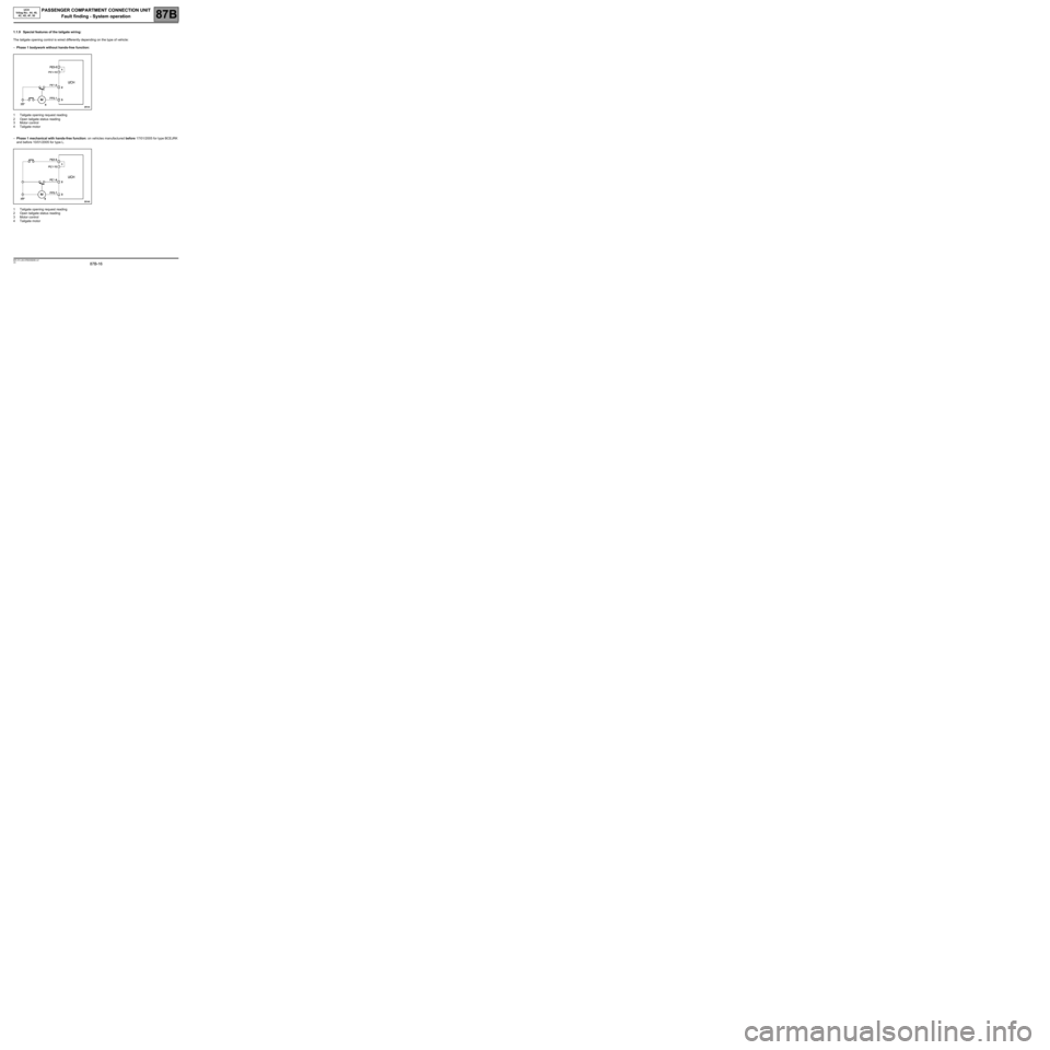
1.1.9 Special features of the tailgate wiring:
The tailgate opening control is wired differently depending on the type of vehicle:
–Phase 1 bodywork without hands-free function:
1Tailgate opening request reading
2Open tailgate status reading
3Motor control
4Tailgate motor
–Phase 1 mechanical with hands-free function: on vehicles manufactured before 17/01/2005 for type BCEJRK
and before 10/01/2005 for type L.
1Tailgate opening request reading
2Open tailgate status reading
3Motor control
4Tailgate motor
Page 18 of 391
PASSENGER COMPARTMENT CONNECTION UNIT
Fault finding - System operation
87B
87B-18
PASSENGER COMPARTMENT CONNECTION UNIT
Fault finding - System operation
87B
87B-18V9 MR-372-J84-87B000$086.mif
UCH
Vdiag No.: 44, 48,
4C, 4D, 4F, 50
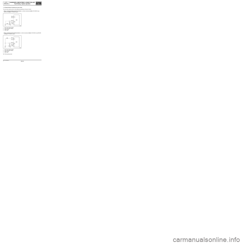
1.1.10 Special features of opening rear screen wiring:
The rear screen opening control is wired differently depending on the type of vehicle:
–Phase 1 mechanical without hands-free function: on vehicles manufactured before 10/01/2005 for type
BCEJRK and before 17/01/2005 for type L.
1Ros* open request reading
2Ros* open status reading
3Motor control
4Ros* motor
–Phase 1 mechanical with hands-free function: on vehicle manufactured before 10/01/2005 for type BCEJRK
and before 17/01/2005 for type L.
1Ros* open request reading
2Ros* open status reading
3Motor control
4Ros* motor
Ros*: Rear opening screen
Page 20 of 391
PASSENGER COMPARTMENT CONNECTION UNIT
Fault finding - System operation
87B
87B-20
PASSENGER COMPARTMENT CONNECTION UNIT
Fault finding - System operation
87B
87B-20V9 MR-372-J84-87B000$086.mif
UCH
Vdiag No.: 44, 48,
4C, 4D, 4F, 50
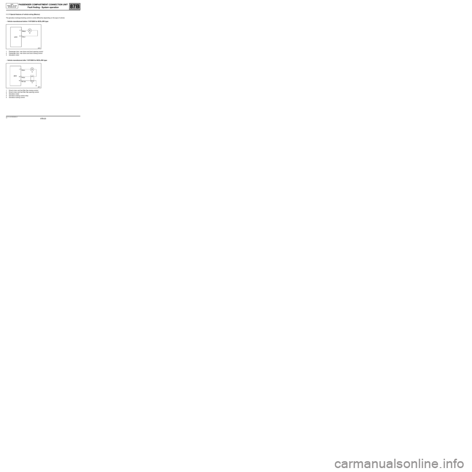
1.1.11 Special features of vehicle wiring (Mexico):
The glovebox locking/unlocking control is wired differently depending on the type of vehicle:
–Vehicle manufactured before 11/07/2005 for BCELJRK type:
1Passenger door, rear doors and boot opening control
2Passenger door, rear doors and boot closing control
3Glovebox motor
–Vehicle manufactured after 11/07/2005 for BCELJRK type:
1Driver's door and fuel filler flap closing control
2Driver's door and fuel filler flap opening control
3Glovebox motor
4Glovebox locking control relay
5Glovebox locking control
Page 21 of 391
PASSENGER COMPARTMENT CONNECTION UNIT
Fault finding - System operation
87B
87B-21
PASSENGER COMPARTMENT CONNECTION UNIT
Fault finding - System operation
87B
87B-21V9 MR-372-J84-87B000$086.mif
1.1.12 Special feature of the rear access aerial wiring on 5-door vehicles:
There are 2 types of fitting for the rear access aerials depending on the fabrication date of the vehicle:
- Vehicles manufactured before January 2007:
An identical access aerial in each door handle.
- Vehicles manufactured after January 2007:
– No access aerial in the rear door handles.
– Access aerials in the front door handles identical to 3-door vehicles.
The vehicle configuration can be identified by reading configuration LC122 REAR ACCESS AERIALS and can be
configured using configuration CF224 REAR ACCESS AERIAL.
UCH
Vdiag No.: 44, 48,
4C, 4D, 4F, 50
1
Page 41 of 391
PASSENGER COMPARTMENT CONNECTION UNIT
Fault finding - System operation
87B
87B-41
PASSENGER COMPARTMENT CONNECTION UNIT
Fault finding - System operation
87B
87B-41V9 MR-372-J84-87B000$129.mif
UCH
Vdiag No.: 44, 48,
4C, 4D, 4F, 50
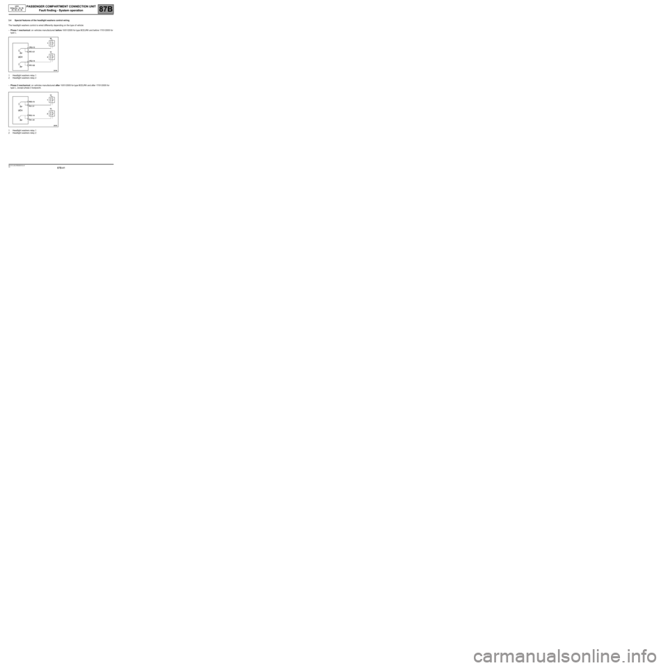
3.4 Special features of the headlight washers control wiring
The headlight washers control is wired differently depending on the type of vehicle:
–Phase 1 mechanical: on vehicles manufactured before 10/01/2005 for type BCEJRK and before 17/01/2005 for
type L.
1Headlight washers relay 1
2Headlight washers relay 2
–Phase 2 mechanical: on vehicles manufactured after 10/01/2005 for type BCEJRK and after 17/01/2005 for
type L, except phase 2 bodywork.
1Headlight washers relay 1
2Headlight washers relay 2
Page 44 of 391
PASSENGER COMPARTMENT CONNECTION UNIT
Fault finding - System operation
87B
87B-44
PASSENGER COMPARTMENT CONNECTION UNIT
Fault finding - System operation
87B
87B-44V9 MR-372-J84-87B000$129.mif
UCH
Vdiag No.: 44, 48,
4C, 4D, 4F, 50
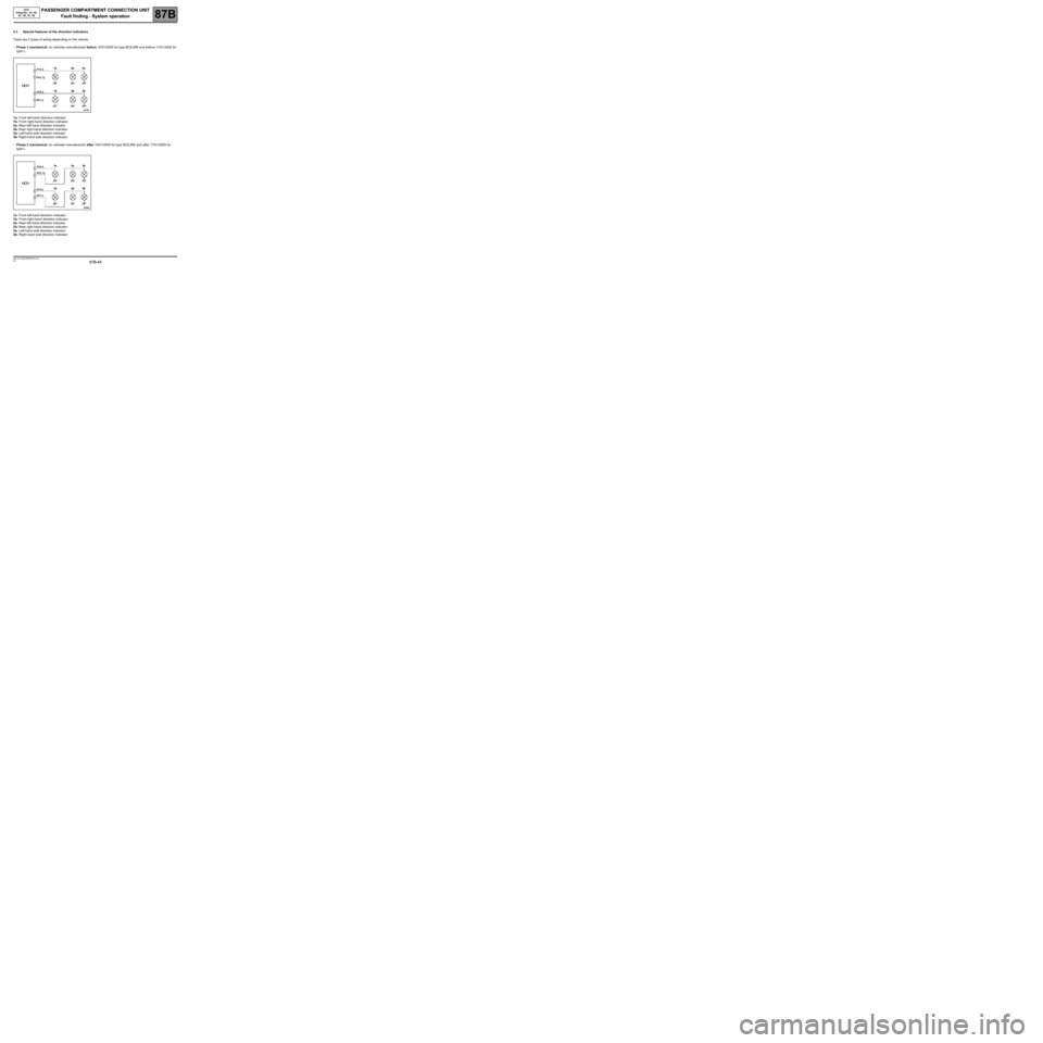
4.3 Special features of the direction indicators
There are 2 types of wiring depending on the vehicle:
–Phase 1 mechanical: on vehicles manufactured before 10/01/2005 for type BCEJRK and before 17/01/2005 for
type L.
1a- Front left-hand direction indicator
1b- Front right-hand direction indicator
2a- Rear left-hand direction indicator
2b- Rear right-hand direction indicator
3a- Left-hand side direction indicator
3b- Right-hand side direction indicator
–Phase 2 mechanical: on vehicles manufactured after 10/01/2005 for type BCEJRK and after 17/01/2005 for
type L.
1a- Front left-hand direction indicator
1b- Front right-hand direction indicator
2a- Rear left-hand direction indicator
2b- Rear right-hand direction indicator
3a- Left-hand side direction indicator
3b- Right-hand side direction indicator
Page 60 of 391
PASSENGER COMPARTMENT CONNECTION UNIT
Fault finding - Configurations and programming
87B
87B-60
PASSENGER COMPARTMENT CONNECTION UNIT
Fault finding - Configurations and programming
87B
87B-60V9 MR-372-J84-87B000$215.mif
UCH
Vdiag No.: 44, 48,
4C, 4D, 4F, 50
6/ CHILD SAFETY LOCK CONFIGURATION PROCEDURE (SC016)
This procedure will enable the child safety system, if fitted to the vehicle, to be configured for optimum running
during the replacement of a UCH.
–Click on the Repair mode and in the Programming menu,
–confirm the line SC016 Child safety,
–follow the procedure and enter the following data:
–CF104 Child safety lock (WITH or WITHOUT),
–confirm and follow the procedure,
–finish by confirming and clearing the stored faults. The child safety function is configured.
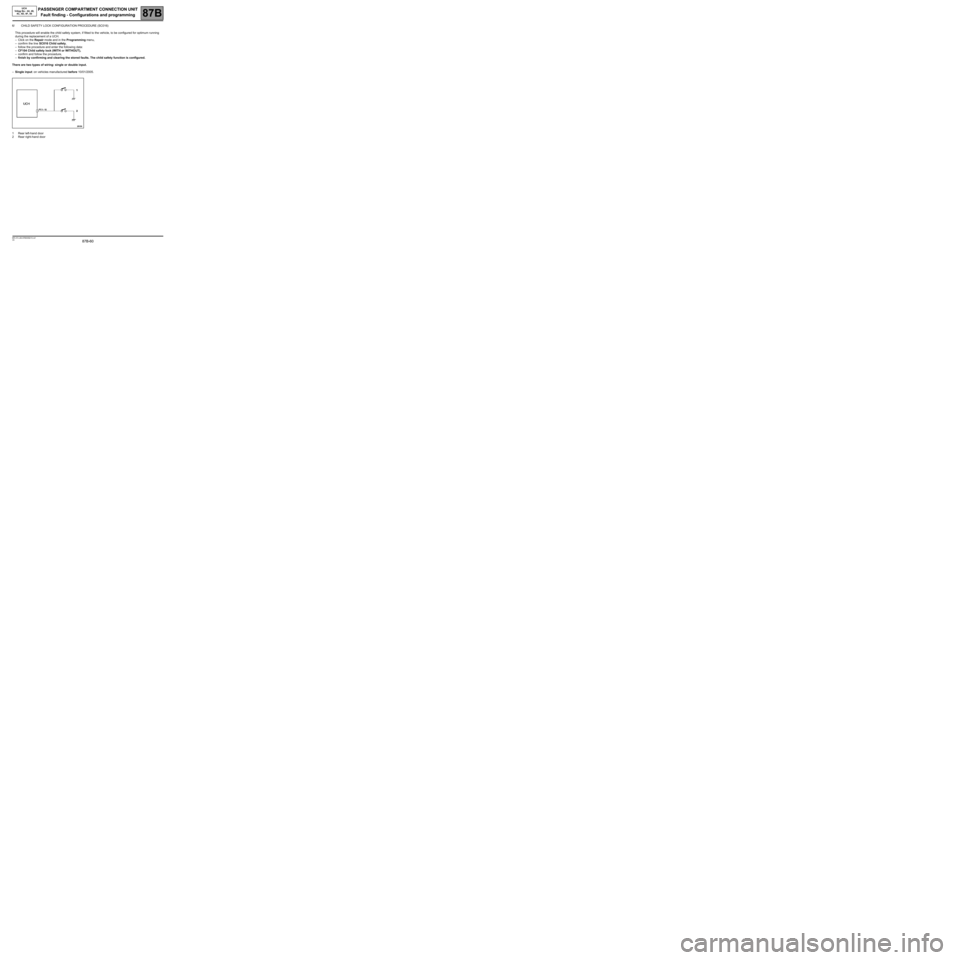
There are two types of wiring: single or double input.
–Single input: on vehicles manufactured before 10/01/2005.
1Rear left-hand door
2Rear right-hand door
Page 75 of 391
PASSENGER COMPARTMENT CONNECTION UNIT
Fault finding - Interpretation of faults
87B
87B-75
PASSENGER COMPARTMENT CONNECTION UNIT
Fault finding - Interpretation of faults
87B
87B-75V9 MR-372-J84-87B000$301.mif
UCH
Vdiag No.: 44, 48,
4C, 4D, 4F, 50
DF003
PRESENT
OR
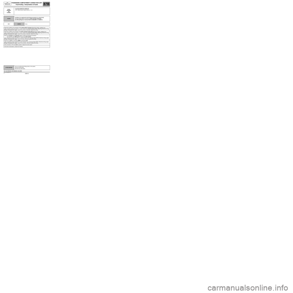
STOREDCLUTCH SWITCH CIRCUIT
CO.1: Short circuit or open circuit to + 12 V
NOTESConditions for applying the fault finding procedure to a stored fault:
The fault appears after a road test at speed > 60 mph (100 km/h).
Use Wiring Diagrams Technical Note for MEGANE II or SCENIC II.
CO.1
NOTESNone.
Check the condition and connection of the clutch switch connector (tabs bent, broken, oxidised, etc.).
If the connector is faulty and if there is a repair method (see Technical Note 6015A, Repairing electrical wiring,
Wiring: Precautions for repair), repair the connector; otherwise, replace the wiring.
Check the condition and connection of the PE1 connector of the UCH (tabs bent, broken, oxidised, etc.).
If the connector is faulty and if there is a repair method (see Technical Note 6015A, Repairing electrical wiring,
Wiring: Precautions for repair), repair the connector; otherwise, replace the wiring.
Check the insulation and continuity against + 12 V of the following connection:
●Connection code 26X between components 645 and 675.
If the connection is faulty and if there is a repair procedure (see Technical Note 6015A, Electrical wiring repair,
Wiring: Precautions for repair), repair the wiring, otherwise replace the wiring.
Check for an earth on connection MAM of component 675.
If the connection is faulty and there is a repair procedure (see Technical Note 6015A, Electrical wiring repair,
Wiring: Precautions for repair), repair the connection, otherwise replace the wiring.
If the connection is OK and earth is present, replace the clutch switch.
If the fault is still present, contact the Techline.
AFTER REPAIRCarry out another fault finding check on the system.
Clear the stored faults.
Deal with any other faults.
UCH_V44_DF003 /UCH_V48_DF003/UCH_V4C_DF003/
UCH_V4D_DF003/UCH_V4F_DF003/UCH_V50_DF003