check engine RENAULT SCENIC 2009 J84 / 2.G Air Conditioning Climate Control Workshop Manual
[x] Cancel search | Manufacturer: RENAULT, Model Year: 2009, Model line: SCENIC, Model: RENAULT SCENIC 2009 J84 / 2.GPages: 60
Page 14 of 60
62B-14
CLIMATE CONTROL
Fault finding – Interpretation of faults62B
V3 MR-372-J84-62B000$060.mif
Vdiag No.: 44
CLIMATE CONTROL
Fault finding – Interpretation of faults
DF001
PRESENT
OR
STOREDCOMPUTER
1.DEF : Internal electronic fault
NOTESConditions for applying the fault finding procedure to stored faults:
Apply this fault finding procedure if the fault appears as present or stored again after:
–clearing the fault and switching the ignition off then back on.
If the fault is stored: clear the fault, switch off the ignition and disconnect the climate control computer supply
fuse.
–Refit the fuse and switch the ignition back on.
–Start the engine and switch on the air conditioning.
If the fault reappears as stored: contact your Techline.
If the fault does not reappear: leave the air conditioning switched on and select various ventilation and air
distribution settings to check that the system is working correctly.
If the fault is present: contact your Techline.
AFTER REPAIRIf the computer has been replaced (at the request of the Techline): reconfigure the
computer (see section Configurations and Programming).
Deal with any other faults.
ACREG X84 1.1
Edition 2
MR-372-J84-62B000$060.mif
Page 28 of 60
62B - 28
CLIMATE CONTROL
Fault finding – Interpretation of parameters62B
V3 MR-372-J84-62B000$080.mif
Vdiag No.: 44
CLIMATE CONTROL
Fault finding – Interpretation of parameters
PR001
INTERIOR TEMPERATURE
NOTESNone.
The climate control computer receives the interior temperature signal through a wire connection.
To ensure this parameter is correct (without using a thermometer), simply read the temperature information
when the vehicle is cold (in the morning). The interior temperature, the exterior temperature and the engine
coolant temperature should be practically the same.
Another way of checking whether this sensor is correct is to check the resistance value of the sensor according
to temperature: refer to the electrical specifications of the sensor in the Help section.
If the temperature displayed by this parameter seems to be incorrect, apply the fault finding procedure for fault:
DF007 Interior temperature sensor circuit.
AFTER REPAIRRepeat the conformity check from the start.
ACREG X84 1.1
Edition 2
MR-372-J84-62B000$080.mif
Page 30 of 60
62B - 30
CLIMATE CONTROL
Fault finding – Interpretation of parameters62B
V3 MR-372-J84-62B000$080.mif
Vdiag No.: 44
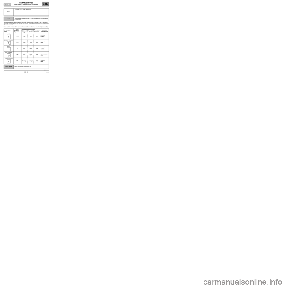
The following table gives the percentages by which the air distribution motor is controlled as well as the opening
status of the lower flaps (footwell flap and under seat duct flap). To view the lower flaps, remove the right-hand and
left-hand lower air ducts.
Values should be checked with the engine switched off and the air conditioning in manual mode (tolerance ± 5%).PR011
DISTRIBUTION FLAP POSITION
NOTESThe values listed below are only given as a guide (they depend on which way the flap
is being moved).
Air distribution
requestPR011
Distribution
flap positionAir flow distribution information
Lower flap
opening status Demisting
flowVent flow Footwell flow
Demisting
100%
High Low NoneCompletely
CLOSED
Demisting + Footwells
60%
High Low HighCompletely
OPEN
Air vents
0%
Low High NoneCompletely
CLOSED
Vents + Footwells
15%
Low High HighApproximately 20%
OPEN
Footwell Ventilation
50%
Average Average HighCompletely
OPEN
AFTER REPAIRRepeat the conformity check from the start.
ACREG X84 1.1
Edition 2
Page 32 of 60
62B - 32
CLIMATE CONTROL
Fault finding – Interpretation of parameters62B
V3 MR-372-J84-62B000$080.mif
Vdiag No.: 44
Controlled values for engine switched off and engine running with air conditioning in manual mode (tolerance ± 5%).
If the values given above are correct but the passenger compartment blower does not work, refer to fault finding
chart ALP 5 No passenger compartment ventilation. PR019
PASSENGER COMPARTMENT BLOWER PWM SETTING
NOTESThe values listed below are only given as a guide.
Passenger compartment
blower speed setting.SPD 0 SPD 1 SPD 2 SPD 3 SPD 4 SPD 5 SPD 6 SPD 7 SPD 8
PR019 passenger
compartment blower
PWM setting.0% 18% 23% 30% 39% 51% 66% 82% 100%
AFTER REPAIRRepeat the conformity check from the start.
ACREG X84 1.1
Edition 2
Page 34 of 60
62B - 34
CLIMATE CONTROL
Fault finding – Interpretation of parameters62B
V3 MR-372-J84-62B000$080.mif
Vdiag No.: 44
PR121
BLOWN AIR TEMPERATURE SETTING
NOTESNone.
This parameter is used to control the temperature inside the passenger compartment. This setting is calculated
by the climate control computer according to interior temperature, exterior temperature and coolant
temperature.
This setting is used to control the mixing motor and the request to operate the passenger compartment air
heating resistors (to reach the temperature requested by the user as quickly as possible in order to optimise
passenger compartment comfort quickly).
The following conditions must be satisfied to allow the UCH to control the passenger compartment air heating
resistors:
–Engine running,
–Passenger compartment blower running (minimum speed 1),
–User temperature setting above 20 ˚C (or automatic mode requested),
–Blown air temperature setting above 65 ˚C,
–Interior temperature below 10 ˚C,
–Exterior temperature below 5 ˚C,
–Engine coolant temperature below 65 ˚C,
–Injection authorisation (ET019 Number of RCHs authorised by injection system < at 1),
–Alternator authorisation (ET018 Number of RCHs authorised by alternator < at 1).
Note:
–Statuses ET017, ET018 and ET019 are indicated by the UCH (see conformity check of air conditioning
function: Section 62A).
–The values given below are average values. The UCH calculates the number of passenger compartment
heating resistors to trigger (ET017 number of RCH required).
AFTER REPAIRRepeat the conformity check from the start.
ACREG X84 1.1
Edition 2
Page 35 of 60
62B - 35
CLIMATE CONTROL
Fault finding – Conformity check62B
V3 MR-372-J84-62B000$090.mif
Vdiag No.: 44
CLIMATE CONTROL
Fault finding – Conformity check
PASSENGER COMPARTMENT VENTILATION SUB-FUNCTION
NOTESOnly carry out this conformity check after a full check with the diagnostic tool (fault
reading and configuration checks).
Test conditions: engine off, ignition on (forced 12 V After ignition).
Air conditioning off
(air conditioning compressor not triggered).
Special note:
The various conformity checks
for the air conditioning function are explained in the
Introduction section.
Note:
–Read the parameters when the vehicle is cold (in the morning) to check the
conformity of the temperature parameters (without thermometer). The two
temperatures should be practically the same (as should the coolant temperature
given by the injection system).
–The invalid values given in this check correspond to the value sent by the diagnostic
tool (substitute value) when the sensor in question is faulty. A sensor fault can be
detected when these invalid values are displayed (this is an important point for
sensors on which fault finding cannot be performed, e.g. exterior temperature
sensor).
Order FunctionParameter or Status
checked or Action Display and Notes Fault finding
1TemperaturesPR001:Interior
temperatureX = interior
temperature ± 5 ˚C
(invalid value: 87.5 ˚C)If there is a fault, refer to the
fault finding procedure
for this parameter.
PR002:Exterior
temperatureX = exterior
temperature ± 5 ˚C
(invalid value: 215 ˚C)
Note: This status is
reset by the climate
control computer but
its source is the UCH.In the event of a fault, refer
to the interpretation of this
parameter (see
Section 87B).
2Solar radiationPR006:Solar radiationfrom 0 W
(no solar radiation) to
400 W
(maximum solar
radiation)
(invalid value:
765 W)In the event of a fault, see
the interpretation of this
parameter.
ACREG X84 1.1
Edition 2
MR-372-J84-62B000$090.mif
Page 37 of 60
62B - 37
CLIMATE CONTROL
Fault finding – Conformity check62B
V3 MR-372-J84-62B000$090.mif
Vdiag No.: 44
COLD LOOP SUB-FUNCTION
NOTESOnly carry out this conformity check after a full check with the diagnostic tool (fault
reading and configuration checks).
Test conditions: engine off, ignition on (forced 12 V After ignition).
Air conditioning off (air conditioning compressor not triggered).
Special note:
The various conformity checks
for the air conditioning function are explained in the
Introduction section.
Order FunctionParameter or Status
checked or Action Display and Notes Fault finding
1Request to
engage the
compressorET143:Air conditioning
request 1ACTIVE for air
conditioning request
(AC button pressed or
AUTO button pressed
with maximum cold
request).
INACTIVE the
opposite.If there is a fault, refer to the
fault finding procedure
for this status.
Note: This status
represents the request from
the climate control
computer to the UCH to
switch on the compressor
(refer to the flowchart in the
system operation section).
2TemperaturePR001:Interior
temperatureX = interior
temperature ± 5 ˚C
(invalid value: 87.5 ˚C)If there is a fault, refer to the
fault finding procedure
for this parameter.
3Passenger
compartment
blowerET141:Passenger
compartment
blowerRUNNING
or
STORED
depending on user
requestIf there is a fault, refer to the
fault finding procedure
for this status.
4Air flapPR012:Mixing flap
position0% = Max cold
position (15 ˚C)
100% = Max hot
position (27 ˚C)If there is a fault, refer to the
fault finding procedure
for this parameter.
5Solar radiationPR006:Solar radiationfrom 0 W (no sunlight)
to 400 W (maximum
sunlight).
(invalid value: 765 W)If there is a fault, refer to the
fault finding procedure
for this parameter.
ACREG X84 1.1
Edition 2
Page 38 of 60
62B - 38
CLIMATE CONTROL
Fault finding – Conformity check62B
V3 MR-372-J84-62B000$090.mif
Vdiag No.: 44
USER SELECTION SUB-FUNCTION
NOTESOnly carry out this conformity check after a full check with the diagnostic tool (fault
reading and configuration checks).
Test conditions: engine off, ignition on (forced 12 V After ignition).
Air conditioning off (air conditioning compressor not triggered).
Special note:
The various conformity checks
for the air conditioning function are explained in the
Introduction section.
Order FunctionParameter or Status
checked or Action Display and Notes Fault finding
1Heated rear
screenET086:Heated rear
screen: manual
modeACTIVE: De-icing
button at the bottom of
the control panel
pressed.
INACTIVE: the
opposite.If there is a fault, refer to the
fault finding procedure
for this status.
ET085:Heated rear
screen:
automatic modeACTIVE: De-icing
button at the top of the
control panel pressed
(See Clear function).
INACTIVE: the
opposite.If there is a fault, refer to the
fault finding procedure
for this status.
2Request to
engage the
compressorET143:Air conditioning
request 1ACTIVE for air
conditioning request
(AC button pressed or
AUTO button pressed
with maximum cold
request).
INACTIVE the
opposite.If there is a fault, refer to the
fault finding procedure
for this status.
Note: This status
represents the request from
the climate control
computer to the UCH to
switch on the compressor
(refer to the flowchart in the
system operation section).
ACREG X84 1.1
Edition 2
Page 39 of 60
62B - 39
CLIMATE CONTROL
Fault finding – Conformity check62B
V3 MR-372-J84-62B000$090.mif
Vdiag No.: 44
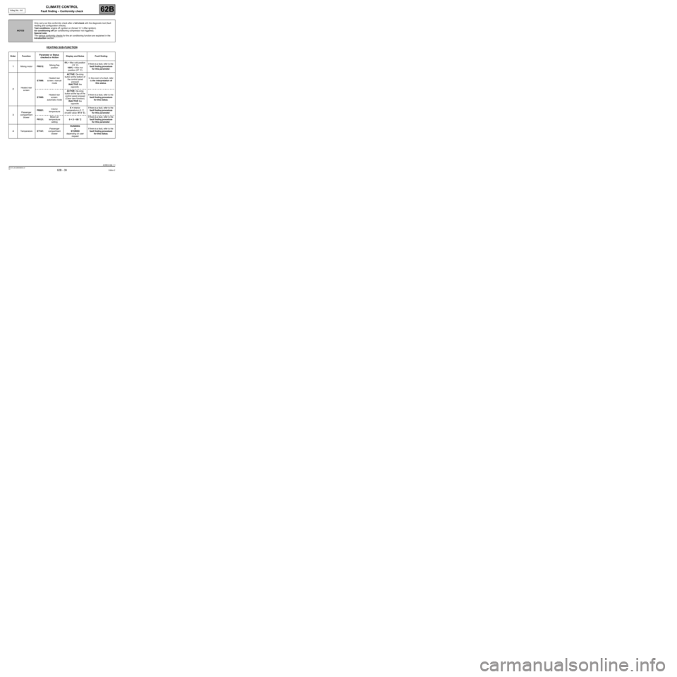
HEATING SUB-FUNCTION
NOTESOnly carry out this conformity check after a full check with the diagnostic tool (fault
reading and configuration checks).
Test conditions: engine off, ignition on (forced 12 V After ignition).
Air conditioning off (air conditioning compressor not triggered).
Special note:
The various conformity checks
for the air conditioning function are explained in the
Introduction section.
Order FunctionParameter or Status
checked or Action Display and Notes Fault finding
1Mixing motorPR012:Mixing flap
position0% = Max cold position
(15 ˚C)
100% = Max hot
position (27 ˚C)If there is a fault, refer to the
fault finding procedure
for this parameter.
2Heated rear
screenET086:Heated rear
screen: manual
modeACTIVE: De-icing
button at the bottom of
the control panel
pressed.
INACTIVE the
opposite.In the event of a fault, refer
to the interpretation of
this status.
ET085:Heated rear
screen:
automatic modeACTIVE: De-icing
button at the top of the
control panel pressed
(Clear view function).
INACTIVE the
opposite.If there is a fault, refer to the
fault finding procedure
for this status.
3Passenger
compartment
blowerPR001:Interior
temperatureX = interior
temperature ± 5 ˚C
(invalid value: 87.5 ˚C).If there is a fault, refer to the
fault finding procedure
for this parameter.
PR121:Blown air
temperature
setting0 < X < 80 ˚CIf there is a fault, refer to the
fault finding procedure
for this parameter.
4TemperatureET141:Passenger
compartment
blowerRUNNING
or
STORED
depending on user
requestIf there is a fault, refer to the
fault finding procedure
for this status.
ACREG X84 1.1
Edition 2
Page 40 of 60
62B - 40
CLIMATE CONTROL
Fault finding – Conformity check62B
V3 MR-372-J84-62B000$090.mif
Vdiag No.: 44
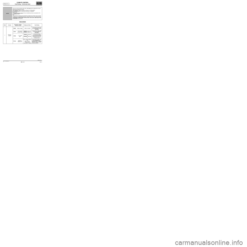
MAIN SCREEN
NOTESOnly carry out this conformity check after a full check with the diagnostic tool (fault
reading and configuration checks).
Test conditions: engine off, ignition on (forced 12 V After ignition).
Air conditioning off (air conditioning compressor not triggered).
Special note:
The various conformity checks for the air conditioning function are explained in the
Introduction section.
Note:
This page lists the statuses and parameters provided by the climate control computer
but which are not associated with the four sub-functions given in the conformity check
(PASSENGER COMPARTMENT VENTILATION, COLD LOOP, USER SELECTION
and HEATING sub-functions).
Order FunctionParameter or Status
checked or Action Display and Notes Fault finding
1Electrical
suppliesPR092:Battery voltage10.5 < X < 14.4 VIn the event of a fault, see
the interpretation of this
parameter
ET007:+ after ignition
computer feedABSENT: Ignition off.
PRESENT: Ignition on.In the event of a fault, refer
to the interpretation of
this status.
ET002:+ 12 V side
lightsABSENT: Side lights
off.
PRESENT: Side lights
on.In the event of a fault,
consult the interpretation
of this status (see 87B,
Passenger compartment
connection unit).
PR122:Night-time
lighting level6% = minimum lighting
level.
99% = maximum
lighting level.
(side lights off: 102%)In the event of a fault, refer
to the interpretation of
parameter PR111 Lighting
dimmer voltage (see 83A,
Instrument panel).
ACREG X84 1.1
Edition 2