check engine RENAULT SCENIC 2009 J84 / 2.G Automatic Transmission AJ0 BVA Workshop Manual
[x] Cancel search | Manufacturer: RENAULT, Model Year: 2009, Model line: SCENIC, Model: RENAULT SCENIC 2009 J84 / 2.GPages: 162
Page 15 of 162
AUTOMATIC TRANSMISSION
Fault finding - Role of components
23A
23A - 15V3 MR-372-J84-23A000$225.mif
AJ0 BVA
Vdiag No.: 04, 05
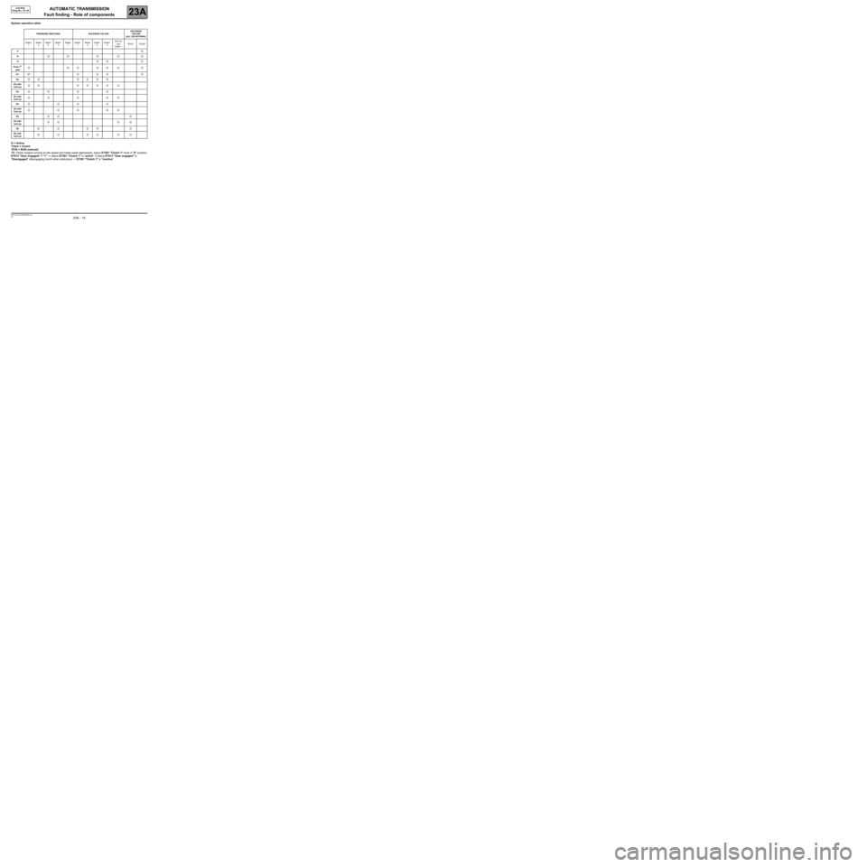
System operation table:
O = Active
*Cltch = Clutch
*EVS = Shift solenoid
*O: Check (engine running at idle speed and brake pedal depressed), status ET261 "Clutch 1" lever in "D" position:
ET013 "Gear engaged" = "1" →→ → →
status ET261 "Clutch 1" is "active"; if status ET013 "Gear engaged" is
"Disengaged" (disengaging clutch when stationary) → ET261 "Clutch 1" is "inactive".
PRESSURE SWITCHES SOLENOID VALVESSOLENOID
VALVES
(ALL OR NOTHING)
Clutch*
1Brake
2Clutch*
2Clutch*
3Brake
1Clutch*
1Brake
2Clutch*
2Clutch*
3lock-up
and
brake 1*EVS1 *EVS2
PO
ROO O O O
NOO O
fixed 1st
gearOOOOOOO
D1O* O O O O
D2OO OOOO
D2 with
lock-upOO OOOO O
D3OO O O
D3 with
lock-upOO O OO
D4OOOO
D4 with
lock-upOOOOO
D5OO O
D5 with
lock-upOO O O
D6OO OO O
D6 with
lock-upOO OO OO
Page 28 of 162
AUTOMATIC TRANSMISSION
Fault finding - Interpretation of faults
23A
23A - 28V3 MR-372-J84-23A000$405.mif
AJ0 BVA
Vdiag No.: 04, 05AUTOMATIC TRANSMISSION
Fault finding - Interpretation of faults
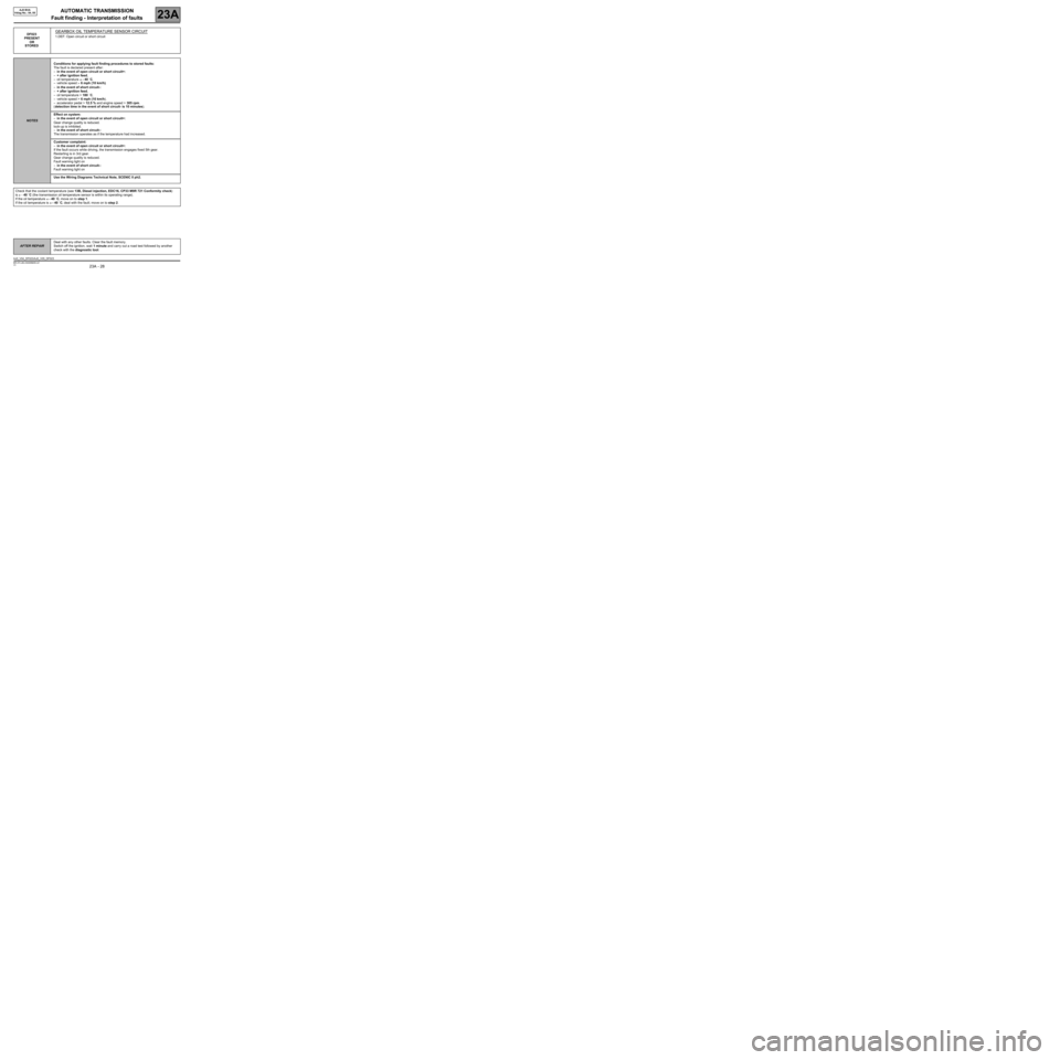
DF023
PRESENT
OR
STOREDGEARBOX OIL TEMPERATURE SENSOR CIRCUIT
1.DEF: Open circuit or short circuit
NOTESConditions for applying fault finding procedures to stored faults:
The fault is declared present after:
–in the event of open circuit or short circuit+:
–+ after ignition feed,
–oil temperature ≤ - 40 ˚C,
–vehicle speed > 6 mph (10 km/h).
–in the event of short circuit-:
–+ after ignition feed,
–oil temperature > 180 ˚C,
–vehicle speed > 6 mph (10 km/h).
–accelerator pedal > 12.5 % and engine speed > 305 rpm.
(detection time in the event of short circuit- is 10 minutes).
Effect on system:
–in the event of open circuit or short circuit+:
Gear change quality is reduced.
lock-up is inhibited.
–in the event of short circuit-:
The transmission operates as if the temperature had increased.
Customer complaint:
–in the event of open circuit or short circuit+:
If the fault occurs while driving, the transmission engages fixed 5th gear.
Restarting is in 3rd gear.
Gear change quality is reduced.
Fault warning light on
–in the event of short circuit-:
Fault warning light on
Use the Wiring Diagrams Technical Note, SCENIC II ph2.
Check that the coolant temperature (see 13B, Diesel injection, EDC16, CP33 M9R 721 Conformity check)
is ≥ - 40 ˚C (the transmission oil temperature sensor is within its operating range).
If the oil temperature ≤ - 40 ˚C, move on to step 1.
If the oil temperature is ≥ - 40 ˚C, deal with the fault; move on to step 2.
AFTER REPAIRDeal with any other faults. Clear the fault memory.
Switch off the ignition, wait 1 minute and carry out a road test followed by another
check with the diagnostic tool.
AJ0_V04_DF023/AJ0_V05_DF023
MR-372-J84-23A000$405.mif
Page 29 of 162
AUTOMATIC TRANSMISSION
Fault finding - Interpretation of faults
23A
23A - 29V3 MR-372-J84-23A000$405.mif
AJ0 BVA
Vdiag No.: 04, 05
DF023
CONTINUED 1
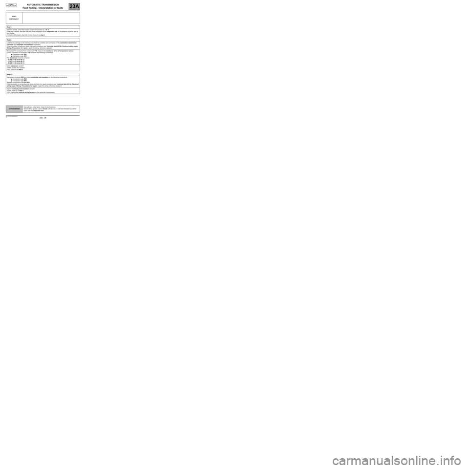
Step 1:
Start the vehicle, check that engine coolant temperature is ≥ 20 ˚C.
If the fault is stored, deal with the other faults displayed on the diagnostic tool. In the absence of faults, end of
fault finding.
If a fault is still present, deal with it, then move on to step 2.
Step 2:
Look for any damage to the harness and check the condition and connection of the automatic transmission
computer and automatic transmission connectors.
If the connection is faulty and there is a repair procedure (see Technical Note 6015A, Electrical wiring repair,
Wiring: Precautions for repair), repair the wiring, otherwise replace it.
Disconnect the connector from component 119, measure the resistance of the oil temperature sensor
(on the connector of component 119) between the following connections:
●Connection code 5BZ,
●Connection code 5BY.
The resistance should be between:
–4.208 ± 0.42 kΩΩ Ω Ω
at 20 ˚C,
–1.947 ± 0.19 kΩΩ Ω Ω
at 40 ˚C,
–0.988 ± 0.09 kΩΩ Ω Ω
at 60 ˚C,
Is the resistance correct?
If YES, contact the Techline.
If NO, move on to step 3.
Stage 3:
Disconnect connector R22 and check continuity and insulation on the following connections:
●Connection code 5BZ,
●Connection code 5BY.
Between components 119 and R22.
If the connection or connections are faulty and there is a repair procedure (see Technical Note 6015A, Electrical
wiring repair, Wiring: Precautions for repair), repair the wiring, otherwise replace it.
Are the continuity and insulation correct?
If YES, move on to step 4.
If NO, replace the external wiring harness on the automatic transmission.
AFTER REPAIRDeal with any other faults. Clear the fault memory.
Switch off the ignition, wait 1 minute and carry out a road test followed by another
check with the diagnostic tool.
Page 31 of 162
AUTOMATIC TRANSMISSION
Fault finding - Interpretation of faults
23A
23A - 31V3 MR-372-J84-23A000$405.mif
AJ0 BVA
Vdiag No.: 04, 05
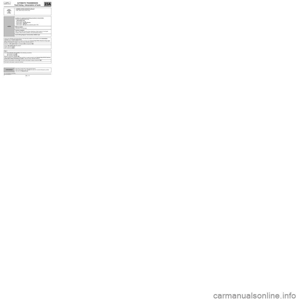
DF038
PRESENT
OR
STOREDTURBINE SPEED SENSOR CIRCUIT
1.DEF: Open circuit or short circuit
NOTESConditions for applying fault finding procedures to stored faults:
The fault is declared present after:
–+ after ignition feed,
–with the engine running,
–vehicle speed > 24 mph (40 km/h),
–engine speed > 1500 rpm,
–turbine speed < 600 rpm and accelerator pedal > 0 %.
Effect on system:
Impossible to calculate gear.
Customer complaint:
Gear on which fault occurred is fixed. Restarting in fixed 3rd gear (no more gear
changes). Manual mode is inhibited. Fault warning light comes on.
Use the Wiring Diagrams Technical Note, SCENIC II ph2.
Look for any damage to the wiring harness, and check the condition and connection of the transmission
computer and the turbine speed sensor.
If the connection is faulty and there is a repair procedure (see Technical Note 6015A, Electrical wiring repair,
Wiring: Precautions for repair), repair the wiring, otherwise replace it.
Check for + after ignition feed on connection AP4 of component 1060.
Is the + after ignition feed still present?
If YES, move on to step 1.
If NO, move on to step 2.
Step 1:
Check the continuity and insulation of the following connections:
●Connection code 5HN.
●Connection code 5DA.
Between components 119 and 1060.
If the connection or connections are faulty and there is a repair procedure (see Technical Note 6015A, Electrical
wiring repair, Wiring: Precautions for repair), repair the wiring, otherwise replace it.
Check the intermediate connector R22, if the fault is still present, replace component 1060.
If the fault is still present, contact the Techline.
AFTER REPAIRDeal with any other faults. Clear the fault memory.
Switch off the ignition, wait 1 minute and carry out a road test followed by another
check with the diagnostic tool.
AJ0_V04_DF038/AJ0_V05_DF038
Page 32 of 162
AUTOMATIC TRANSMISSION
Fault finding - Interpretation of faults
23A
23A - 32V3 MR-372-J84-23A000$405.mif
AJ0 BVA
Vdiag No.: 04, 05
DF038
CONTINUED
Step 2:
Check the continuity and insulation of the following connection:
●Connection code AP4 between components 119 and 1337.
If the connection is faulty and there is a repair procedure (see Technical Note 6015A, Electrical wiring repair,
Wiring: Precautions for repair), repair the wiring, otherwise replace it.
Check for + after ignition feed on connection AP4 of component 1337.
Is the + after ignition feed still present?
If YES, move on to step 1.
If NO (see 87G, Engine compartment connection unit).
If the fault is still present, contact the Techline.
AFTER REPAIRDeal with any other faults. Clear the fault memory.
Switch off the ignition, wait 1 minute and carry out a road test followed by another
check with the diagnostic tool.
Page 33 of 162
AUTOMATIC TRANSMISSION
Fault finding - Interpretation of faults
23A
23A - 33V3 MR-372-J84-23A000$405.mif
AJ0 BVA
Vdiag No.: 04, 05
If the fault is stored:DF067
PRESENT
OR
STORED
LEVER POSITION SWITCH CIRCUIT
1.DEF: Open circuit or short circuit
NOTESConditions for applying fault finding procedures to stored faults:
The fault is declared present after:
–in the event of open circuit or short circuit-:
–+ after ignition feed and change of lever position.
–in the event of short circuit+:
–+ after ignition feed, initial lever position: Position "P", "R", "N" or "D".
Effect on system:
The lever value is held at its previous valid position until the fault is confirmed. Then
the lever position becomes DRIVE (internal software variable) irrespective of the fault.
–If the fault is present and the lever in position "P", the transmission is in "N", hydraulic
neutral.
–If the fault is present and the lever in position "R", the transmission is in "R", hydraulic
reverse.
–If the fault is present and the lever in position "N", the transmission is in "N", hydraulic
neutral.
–If the fault is present and the lever in position "D", the transmission is in "D", hydraulic
forward gear.
lock-up is inhibited.
Customer complaint:
No lever position display on the instrument panel following fault confirmation and
starting impossible.
If the engine is already running when the fault occurs, there is jolting when shifting from
"P" or "N" to "R" or "D".
Fault warning light comes on.
Use the Wiring Diagrams Technical Note, SCENIC II ph2.
Note:
It is possible to produce this fault if the driver or operator voluntarily keep the lever between two normal positions
for longer than 2 seconds.
AFTER REPAIRDeal with any other faults. Clear the fault memory.
Switch off the ignition, wait 1 minute and carry out a road test followed by another
check with the diagnostic tool.
AJ0_V04_DF067/AJ0_V05_DF067
Page 35 of 162
AUTOMATIC TRANSMISSION
Fault finding - Interpretation of faults
23A
23A - 35V3 MR-372-J84-23A000$405.mif
AJ0 BVA
Vdiag No.: 04, 05
DF067
CONTINUED 2
Step 2:
If the continuity and insulation are not correct, disconnect the connector from component 779, check the
continuity and insulation of the following connections (on the connector of component 779):
Position of gear lever = P:
●Connection code 5DF.
●Connection code AP4.
Position of gear lever = R:
●Connection code 5DG.
●Connection code AP4.
Position of gear lever = N:
●Connection code 5DH.
●Connection code AP4.
Position of gear lever = N:
●Connection code 5DJ.
●Connection code AP4.
If the connection or connections are faulty and there is a repair procedure (see Technical Note 6015A, Electrical
wiring repair, Wiring: Precautions for repair), repair the wiring, otherwise replace it.
Are the continuity and insulation correct?
If YES, replace the external wiring harness on the automatic transmission.
If NO, replace the multifunction switch.
If the fault is still present, contact the Techline.
Stage 3:
Check the continuity and insulation of the following connection:
●connection code AP4,
between components 119 and 1337.
If the connection is faulty and there is a repair procedure (see Technical Note 6015A, Electrical wiring repair,
Wiring: Precautions for repair), repair the wiring, otherwise replace it.
Check for + after ignition feed on connection AP4 of component 1337.
Is the + after ignition feed still present?
If YES, move on to step 1.
If NO (see 87G, Engine Compartment Connection Unit).
If the fault is still present, contact the Techline.
AFTER REPAIRDeal with any other faults. Clear the fault memory.
Switch off the ignition, wait 1 minute and carry out a road test followed by another
check with the diagnostic tool.
Page 36 of 162
AUTOMATIC TRANSMISSION
Fault finding - Interpretation of faults
23A
23A - 36V3 MR-372-J84-23A000$405.mif
AJ0 BVA
Vdiag No.: 04, 05
DF084
PRESENT
OR
STOREDMULTIPLEX NETWORK
1.DEF: No multiplex frameworks or invalid values (signal producing computer
problem or CAN connection fault).
NOTESConditions for applying fault finding procedures to stored faults:
The fault is declared present after + APC.
Effect on system:
Engine does not start.
No lever position display on the instrument panel.
Note: the effects of the fault disappear immediately after the multiplex line bus is
re-established.
Customer complaint:
Engine does not start.
No lever position display on the instrument panel.
Jolting during gear changes.
Note: the effects of the fault disappear immediately after the multiplex line bus is
re-established.
Use the Wiring Diagrams Technical Note, SCENIC II ph2.
Run a multiplex network test (see 88B, Multiplex).
Check the continuity and insulation against earth of the following connections:
●Connection code 3MS.
●Connection code 3MT.
Between components 119 and 120.
If the connection or connections are faulty and there is a repair procedure (see Technical Note 6015A, Electrical
wiring repair, Wiring: Precautions for repair), repair the wiring, otherwise replace it.
If the fault is still present, contact the Techline.
AFTER REPAIRDeal with any other faults. Clear the fault memory.
Switch off the ignition, wait 1 minute and carry out a road test followed by another
check with the diagnostic tool.
AJ0_V04_DF084/AJ0_V05_DF084
Page 41 of 162
AUTOMATIC TRANSMISSION
Fault finding - Interpretation of faults
23A
23A - 41V3 MR-372-J84-23A000$405.mif
AJ0 BVA
Vdiag No.: 04, 05
DF086
PRESENT
OR
STOREDEVS2 SEQUENCE SOLENOID VALVE CIRCUIT
CO.1: Short circuit or open circuit to + 12 V
NOTESConditions for applying fault finding procedures to stored faults:
The fault is declared present after:
–in the event of short circuit+:
Lever in "Drive" position, gear engaged = 2, 3, 4, 5, 6,
and Inconsistency between the solenoid valve control status and the control voltage.
–in the event of open circuit:
Lever in "Drive" position, lock-up closed, gear engaged = 2, 3, 4, 5, 6,
and Inconsistency between the solenoid valve control status and the control voltage.
–in the event of short circuit-:
Lever in "Drive" position, lock-up open, gear engaged = 1, 2, 3, 4, 5, 6,
OR Gear 1 with engine braking,
and Inconsistency between the solenoid valve control status and the control voltage.
OR
Running command AC002 "Shift solenoid 2".
Effect on system:
–in the event of short circuit+:
If the fault appears with the lock-up closed, gear engaged in "Drive" position = 2, 3, 4,
5, 6, automatic transmission is locked.
–in the event of open circuit:
No effect.
–in the event of short circuit-:
Risk of stalling in 1st with engine braking.
Customer complaint:
If the fault occurs while driving, the transmission engages fixed 5th gear.
Restarting is in 3rd gear.
Fault warning light comes on.
Use the Wiring Diagrams Technical Note, SCENIC II ph2.
Look for any damage to the harness and check the condition and connection of the automatic transmission
computer and automatic transmission connectors.
If the connection is faulty and there is a repair procedure (see Technical Note 6015A, Electrical wiring repair,
Wiring: Precautions for repair), repair the wiring, otherwise replace it.
Check for + after ignition feed on connection 5LW of component 754.
If + after ignition feed is present, move on to step 1.
If + after ignition feed is not present, move on to step 8.
AFTER REPAIRDeal with any other faults. Clear the fault memory.
Switch off the ignition, wait 1 minute and carry out a road test followed by another
check with the diagnostic tool.
AJ0_V04_DF086/AJ0_V05_DF086
Page 51 of 162
AUTOMATIC TRANSMISSION
Fault finding - Interpretation of faults
23A
23A - 51V3 MR-372-J84-23A000$405.mif
AJ0 BVA
Vdiag No.: 04, 05
*EVS2 = sequence solenoid valve 2DF097
PRESENT
OR
STORED
CONVERTER lock-up
1.DEF: CONVERTER LOCK-UP CONTROL
NOTESOrder of priority in the event of more than one fault:
If there is a combination of the following faults:
–DF097 "Converter lock-up",
–DF086 "Sequence solenoid valve circuit "EVS2*""
–DF306 "Lock-up/brake 1 solenoid valve circuit",
deal first with faults DF086 "Sequence solenoid valve "EVS2*"" and DF306 "Lock-
up/brake 1 solenoid valve circuit".
Conditions for applying fault finding procedures to stored faults:
The fault is declared present after:
If in lock-up:
Lever in Manual position,
and difference in *slippage speed ≥ 40 + Vehicle speed / 2 for a certain time,
and EVS2* solenoid valve control status > 95 %.
In the event of slippage:
Lever in Manual position,
and difference in slippage speed ≥ 40 + slippage speed setpoint for a certain time,
and EVS2* solenoid valve control status > 95 %.
*slippage = engine speed - turbine speed
Effect on system:
Increase in oil temperature.
–In the event of engagement fault, lock-up inhibited.
–In the event of slippage fault, lock-up slippage inhibited.
Customer complaint:
Warning light on.
Use the Wiring Diagrams Technical Note, SCENIC II ph2.
AFTER REPAIRDeal with any other faults. Clear the fault memory.
Switch off the ignition, wait 1 minute and carry out a road test followed by another
check with the diagnostic tool.
AJ0_V04_DF097/AJ0_V05_DF097