check engine RENAULT SCENIC 2009 J84 / 2.G Engine And Peripherals EDC16 Workshop Manual
[x] Cancel search | Manufacturer: RENAULT, Model Year: 2009, Model line: SCENIC, Model: RENAULT SCENIC 2009 J84 / 2.GPages: 273
Page 175 of 273
DIESEL INJECTION
Fault finding – Interpretation of statuses13B
13B - 175V3 MR-372-J84-13B250$630.mif
NO
EDC16
PROGRAM NO.: C1
Vdiag No.: 51
ET007
PREHEATING UNIT CONTROL
NOTESSpecial notes:
Only perform these tests if the statuses do not correspond with the system
programming functions.
YES
When the vehicle is started from cold, the injection computer controls the pre-
postheating unit so that the vehicle can be started.
Status ET007 becomes YES a few seconds after the ignition is switched on and during
pre/postheating.
If the vehicle does not start and status ET007 becomes YES, check:
–the F2 (70A) supply fuse on the preheating unit, located on the power supply fuse
plate in the engine connection unit, below the Protection and Switching Unit,
–the resistance of the heater plugs.
Replace any plug whose resistance is not below 2 Ω.
If the vehicle starts and status ET007 remains YES during the engine operating phase,
refer to the interpretation of faults:
–DF017 Preheating relay control circuit.
–DF025 Preheating unit diagnostic connection.
After the engine is started and the preheating phase, the injection computer should stop
the pre-postheating unit operating.
Status ET007 should become NO.
In the event that the vehicle does not start and status ET007 remains NO, check the
continuity and absence of interference resistance of the following connections:
Injection computer Track A4 grey
32-track connector CTrack 9 preheating unit
Injection computer Track E2 grey
32-track connector CTrack 8 preheating unit
Repair if necessary.
If the fault is still present, refer to the interpretation of faults:
–DF017 Preheating relay control circuit.
–DF025 Preheating unit diagnostic connection.
AFTER REPAIRCarry out a road test followed by a complete test with the diagnostic tool.
EDC16_V51_ET007
Page 176 of 273
DIESEL INJECTION
Fault finding – Interpretation of statuses13B
13B - 176V3 MR-372-J84-13B250$630.mif
EDC16
PROGRAM NO.: C1
Vdiag No.: 51
ET014
CHECK COOLING FAN 1
NOTESSpecial notes:
Only perform these tests if the statuses do not correspond with the system
programming functions.
NOTE:
Status ET014 test and status ET022 GMV1 low speed request change their status at the same time.
RUNNING
The low-speed engine fan unit is supplied in three scenarios:
–the engine coolant temperature is above 89 ˚C;
–the air conditioning is operating
–the injection computer has system faults that could lead to the engine overheating.
When the low-speed engine fan is supplied:
–status ET014 GMV 1 test becomes RUNNING status ET022 Low speed GMV
request becomes ACTIVE.
If the low speed GMV does not work (see 87G, engine compartment connection unit).
The low-speed engine fan assembly stops when:
–the engine coolant temperature is below 89 ˚C;
–the air conditioning is not switched on by the driver.
STOPPED
IMPORTANTWARNING
If the UPC does not detect the injection computer frames, the low speed engine
fan is supplied until the battery is completely discharged.
In the event that the low-speed engine fan assembly is faulty, the high-speed
engine fan assembly will then be activated.
AFTER REPAIRCarry out a road test followed by a complete test with the diagnostic tool.
EDC16_V51_ET014
Page 177 of 273
DIESEL INJECTION
Fault finding – Interpretation of statuses13B
13B - 177V3 MR-372-J84-13B250$630.mif
STOPPED
EDC16
PROGRAM NO.: C1
Vdiag No.: 51
ET015
CHECK COOLING FAN 2
NOTESSpecial notes:
Only perform these tests if the statuses do not correspond with the system
programming functions.
NOTE:
Status ET015 GMV 2 test and status ET021 High speed GMV request change their status at the same time.
RUNNING
The engine fan assembly can be supplied when:
–the engine coolant temperature is above 99 ˚C.
–the injection computer has system faults that could lead to the engine overheating.
When the high speed fan is supplied:
–status ET015 GMV 2 test becomes RUNNING and status ET021 High speed GMV
request becomes ACTIVE.
The high-speed engine fan assembly stops when:
–the engine coolant temperature is below 99 ˚C;
IMPORTANTWARNING
If the UPC does not detect the injection computer frames, the low speed engine
fan is supplied until the battery is completely discharged.
In the event that the low-speed engine fan assembly is faulty, the high-speed
engine fan assembly will then be activated.
AFTER REPAIRCarry out a road test followed by a complete test with the diagnostic tool.
EDC16_V51_ET015
Page 182 of 273
DIESEL INJECTION
Fault finding – Interpretation of statuses13B
13B - 182V3 MR-372-J84-13B250$630.mif
EDC16
PROGRAM NO.: C1
Vdiag No.: 51
ET042
CONTINUED 1
INACTIVEWhen the main switch is in rest position (or neutral), status ET042 is "INACTIVE".
If "CRUISE CONTROL" or "SPEED LIMITER" appears despite the main button being in
the rest position (or neutral), carry out the following operations:
Check the connections of the cruise control/speed limiter main switch.
Check for + 12 V APC on the main switch connector.
–Connection code AP43 of component 1081 (Mégane II)
–Connection code AP43 of component 1546 (Scénic II)
Disconnect the main switch and with it in the rest position, check the insulation between:
–Connection codes AP43 and 3FX of component 1081 (Mégane II)
–Connection codes AP43 and 3PD of component 1081 (Mégane II)
–Connection codes AP43 and 3FX of component 1546 (Scénic II)
–Connection codes AP43 and 3PD of component 1546 (Scénic II)
Check the continuity between connections AP43 and 3PD of component 1081
(Mégane II) and component 1546 (Scénic II) in speed limiter position.
Check the continuity between connections AP43 and 3FX of component 1081
(Mégane II) and component 1546 (Scénic II) in cruise control position.
If these checks are not in order, replace the switch.
Check the insulation, continuity and the absence of interference resistance on the
following connections:
–Connection code 3FX,
–connection code 3PD.
Between components 1081 and 120 (Mégane II)
Between components 1546 and 120 (Scénic II)
Also check the engine management computer connectors.
If there is a repair method (see Technical Note 6015A, Repairing electrical wiring,
Wiring: Repair precautions), repair the wiring, otherwise replace it.
AFTER REPAIRSwitch off the ignition and carry out a road test followed by a test with the diagnostic
tool.
Page 183 of 273
DIESEL INJECTION
Fault finding – Interpretation of statuses13B
13B - 183V3 MR-372-J84-13B250$630.mif
EDC16
PROGRAM NO.: C1
Vdiag No.: 51
ET042
CONTINUED 2
SPEED LIMITERWhen the driver presses the main switch in the speed limiter position, status ET042
becomes SPEED LIMITER.
If CRUISE CONTROL or INACTIVE appears although the switch was pressed in the
speed limiter position, carry out the following operations:
Check the connections of the cruise control/speed limiter main switch.
Check for + 12 V after ignition feed on the main switch connector.
●Connection code AP43 of component 1081 (Mégane II).
●Connection code AP43 of component 1546 (Scénic II).
Disconnect the main switch and with it in the rest position, check the insulation between:
●Connection code AP43 and 3FX, of component 1081 (Mégane II).
●Connection code AP43 and 3PD, of component 1081 (Mégane II).
●Connection code AP43 and 3FX, of component 1546 (Scénic II).
●Connection code AP43 and 3PD, of component 1546 (Scénic II).
–Check the continuity between connections AP43 and 3PD of component 1081
(Mégane II) and component 1546 (Scénic II) in speed limiter position.
–Check the continuity between connections AP43 and 3FX of component 1081
(Mégane II) and component 1546 (Scénic II) in cruise control position.
If these checks show incorrect values, replace the main switch.
Check the insulation, continuity and the absence of interference resistance on the
following connections:
●Connection code 3FX,
●Connection code 3PD,
between components 1081 and 120 (Mégane II).
between components 1546 and 120 (Scénic II).
Also check the engine management computer connectors.
If there is a repair method (See Technical Note 6015A, Repairing electrical wiring,
Wiring: Precautions for repair), repair the wiring, otherwise replace the wiring.
AFTER REPAIRSwitch off the ignition and carry out a road test followed by a test with the diagnostic
tool.
Page 184 of 273
DIESEL INJECTION
Fault finding – Interpretation of statuses13B
13B - 184V3 MR-372-J84-13B250$630.mif
EDC16
PROGRAM NO.: C1
Vdiag No.: 51
ET042
CONTINUED 3
CRUISE CONTROLWhen the driver presses the main switch in the cruise control position, status ET042
becomes CRUISE CONTROL.
If SPEED LIMITER or INACTIVE appears although the driver pressed the switch in the
cruise control position, carry out the following operations:
Check the connections of the cruise control/speed limiter main switch.
Check for + 12 V after ignition feed on the main switch connector.
●Connection code AP43 of component 1081 (Mégane II).
●Connection code AP43 of component 1546 (Scénic II).
Disconnect the switch and when it is in the rest position, check the insulation between:
●Connection code AP43 and 3FX, of component 1081 (Mégane II).
●Connection code AP43 and 3PD, of component 1081 (Mégane II).
●Connection code AP43 and 3FX, of component 1546 (Scénic II).
●Connection code AP43 and 3PD, of component 1546 (Scénic II).
–Check the continuity between connections AP43 and 3PD of component 1081
(Mégane II) or component 1546 (Scénic II) in speed limiter position.
–Check the continuity between connections AP43 and 3FX of component 1081
(Mégane II) or component 1546 (Scénic II) in cruise control position.
If these checks show incorrect values, replace the main switch.
Check the insulation, continuity and the absence of interference resistance on the
following connections:
●Connection code 3FX,
●connection code 3PD.
Between components 1081 and 120 (Mégane II).
Between components 1546 and 120 (Scénic II).
Also check the engine management computer connectors.
If there is a repair method (see Technical Note 6015A, Repairing electrical wiring,
Wiring: Repair precautions), repair the wiring, otherwise replace it.
AFTER REPAIRSwitch off the ignition and carry out a road test followed by a test with the diagnostic
tool.
Page 192 of 273
DIESEL INJECTION
Fault finding – Interpretation of statuses13B
13B - 192V3 MR-372-J84-13B250$630.mif
NO
EDC16
PROGRAM NO.: C1
Vdiag No.: 51
ET341
IMMOBILISER CODE PROGRAMMED
NOTESSpecial notes:
Only perform these tests if the statuses do not correspond with the system
programming functions.
YES
Status ET341 becomes YES if dialogue is established between the UCH and the
injection computer and the card code is recognised.
The engine is only authorised to start if the code is recognised by the UCH computer and
status ET003 Engine immobiliser is INACTIVE.
The code remains NO if dialogue between the UCH and the injection computer is not
possible. Status ET003 Engine immobiliser is ACTIVE.
The cause of the malfunction may be due to the incorrect programming of the cards,
(see 97B, Passenger compartment connection unit, configuration and
programming); follow the card programming procedure.
If the malfunction is not due to the card codes, test the multiplex network (when fault
finding is carried out for functions) and check that there is dialogue between the UCH,
the Protection and Switching Unit and the injection computer.
If dialogue is not established, contact the Techline.
AFTER REPAIRCarry out a road test followed by a complete test with the diagnostic tool.
EDC16_V51_ET341
Page 195 of 273
DIESEL INJECTION
Fault finding – Interpretation of statuses13B
13B - 195V3 MR-372-J84-13B250$630.mif
STATUS 3
EDC16
PROGRAM NO.: C1
Vdiag No.: 51
ET415
1(CONTINUED)
STATUS 2
Brake pedal depressed
The cruise control function is deactivated when the brake pedal is depressed.
Status ET415 becomes STATUS 2 when driving with cruise control active (ET042
Cruise control/Speed limiter: CRUISE CONTROL) and the brake pedal is depressed.
This deactivates cruise control.
Reinitialise status ET415 on the injection computer by running command RZ007
“Fault memory”.
If status ET415 becomes STATUS 2 without pressing the brake pedal, consult the
interpretation of statuses ET704 and ET705 Brake contact No. 1 and No. 2.
Clutch pedal depressed
Manual gearbox ONLY
The cruise control function is deactivated when the gearbox is not coupled to the engine
(clutch pedal depressed).
Status ET415 becomes STATUS 3 when driving with cruise control active (ET042
Cruise control/speed limiter: CRUISE CONTROL) and the clutch pedal is depressed.
This deactivates cruise control.
Reinitialise status ET415 on the injection computer by running command RZ007
“Fault memory”.
If status ET415 becomes STATUS 3 without the clutch pedal being depressed, consult
the interpretation of status ET405: Clutch pedal.
If the vehicle is fitted with automatic transmission:
Test the multiplex network: check the configuration of the multiplex network in relation to
the vehicle's technical specification, especially the configuration of the automatic
transmission computer (see 88B, Multiplexing)
AFTER REPAIRSwitch off the ignition and carry out a road test followed by a test with the diagnostic
tool.
1
Page 201 of 273
DIESEL INJECTION
Fault finding – Interpretation of statuses13B
13B - 201V3 MR-372-J84-13B250$630.mif
STATUS 18
STATUS 20
STATUS 21
STATUS 11, 22
STATUS 8
STATUS 4, 17
STATUS 2
STATUS 3, 14, 16
STATUSES 1, 5, 6,
7, 9, 10, 12, 13, 15,
19, 23, 24
EDC16
PROGRAM NO.: C1
Vdiag No.: 51
ET651
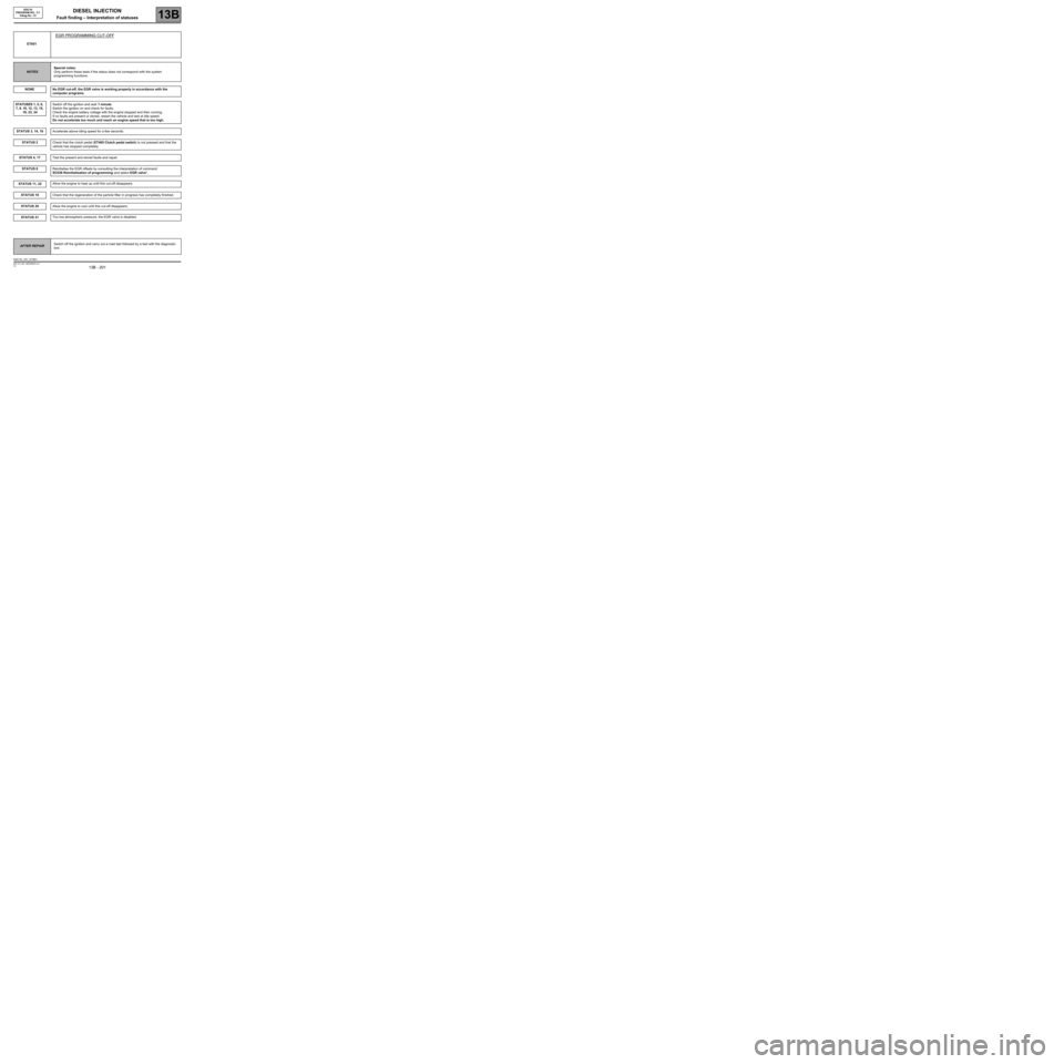
EGR PROGRAMMING CUT-OFF
NOTESSpecial notes:
Only perform these tests if the status does not correspond with the system
programming functions.
NONE
No EGR cut-off, the EGR valve is working properly in accordance with the
computer programs.
Switch off the ignition and wait 1 minute.
Switch the ignition on and check for faults.
Check the engine battery voltage with the engine stopped and then running.
If no faults are present or stored, restart the vehicle and test at idle speed.
Do not accelerate too much and reach an engine speed that is too high.
Accelerate above idling speed for a few seconds.
Check that the clutch pedal (ET405 Clutch pedal switch) is not pressed and that the
vehicle has stopped completely.
Test the present and stored faults and repair.
Reinitialise the EGR offsets by consulting the interpretation of command
SC036 Reinitialisation of programming and select EGR valve".
Allow the engine to heat up until this cut-off disappears.
Check that the regeneration of the particle filter in progress has completely finished.
Allow the engine to cool until this cut-off disappears.
Too low atmospheric pressure, the EGR valve is disabled.
AFTER REPAIRSwitch off the ignition and carry out a road test followed by a test with the diagnostic
tool.
EDC16_V51_ET651
Page 210 of 273
DIESEL INJECTION
Fault finding – Interpretation of commands13B
13B -210V3 MR-372-J84-13B250$765.mif
EDC16
PROGRAM No: C1
Vdiag No.: 51
SC002
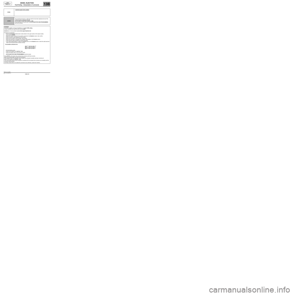
ENTER INJECTOR CODES
NOTESThis command should be run after the injectors have been replaced and only if the
vehicle has been configured with IMA.
(ET104 USE OF INJECTOR CODES to YES).
If this command is not performed, the DF276 INJECTOR CODE PROGRAMMING
fault will be present.
WARNING
The letters J and Q, and figures 0 and 9 are not used in IMA coding.
If these characters are used the entry will be invalid.
Cylinder no. 1 is the cylinder located at the engine flywheel end.
Procedure to be followed:
–Read the 6-character alphanumeric codes etched on the upper section of the injector bodies.
–Use command SC002.
–Select the cylinder number for the cylinder concerned in the Desired, column, then confirm.
–Enter the injector code displayed for the cylinder.
–Enter the new codes for each cylinder, then confirm.
–When the command is completed, the modified codes appear in the Current column.
–Check that the codes correspond to those read earlier.
–If the codes entered appear in neither the Current column nor the Desired column, check the codes read and
make sure the data has been entered correctly,
The possible confusions are:
digit "1" with the letter "I"
figure 8 with the letter B
figure 5 with the letter S
–Exit fault finding mode.
–Switch off the ignition and wait for 1 min.
–Switch the ignition back on and check for faults.
–DF276 INJECTOR CODE PROGRAMMING should be stored.
If fault DF276 is still present, the command has not been performed correctly.
Start the procedure again and follow the instructions.
If the codes are still not recognised, check whether the computer's standby has been correctly set:
Switch off the ignition and wait for 1 min.
If the warning light flashes when the ignition is switched off, the computer has not been put on standby and the
command will be ignored.
If all these checks still do not enable the command to be confirmed, contact the Techline.
EDC16_V51_SC002