stop start RENAULT SCENIC 2009 J84 / 2.G Engine And Peripherals EDC16 Workshop Manual
[x] Cancel search | Manufacturer: RENAULT, Model Year: 2009, Model line: SCENIC, Model: RENAULT SCENIC 2009 J84 / 2.GPages: 273
Page 12 of 273
DIESEL INJECTION
Fault finding – System operation13B
13B - 12V3 MR-372-J84-13B250$135.mif
EDC16
PROGRAM No: C1
Vdiag No.: 51
c) Hosted functions:
Air conditioning management assistance:
In the case of vehicles with climate control, the EDC16 system has the option of deactivating the air conditioning via
the UCH, under certain conditions of use:
–when requested by the driver,
–when starting the engine,
–if the engine overheats (in order to reduce the power the engine has to supply),
–when the engine speed is kept at a very high level (to protect the compressor),
–during transitory phases (such as demands for high acceleration when overtaking, anti-stall and start-up) These
conditions are only taken into account when they do not occur repeatedly, to prevent instability in the system
(erratic deactivations),
–when certain faults appear.
Cold loop air conditioning management:
The air conditioning is the cold loop type and its management shared between several computers.
The injection computer is responsible for:
–authorising cold requests according to the refrigerant pressure, the engine coolant temperature and the engine
speed,
–calculating the power absorbed by the compressor (from the refrigerant pressure),
–requesting operation of the GMV, from the UPC, according to the vehicle speed, the refrigerant pressure and the
engine coolant temperature.
The driver requests the air conditioning to be switched on by means of the ventilation selector coupled to a switch.
The cold air request is authorised or denied depending on the pressure measured. If this pressure is outside the
operating limits, the cold loop program is not activated.
Management of the damper valve:
The damper valve currently has three functions:
–the valve closes in order to block the passage of air towards the cylinders to shut off the engine. The aim of this is
to stop the engine as quickly as possible and to reduce instabilities as the engine is switched off.
–"valving" function depending on the engine operation: the damper valve closes by a few % to create a ''venturi''
effect at the EGR valve passage section.
The aim of this is to accelerate the air flow of EGR gases and to reduce the emission of pollutants.
Page 35 of 273
DIESEL INJECTION
Fault finding – Interpretation of faults13B
13B-35V3 MR-372-J84-13B250$315.mif
EDC16
PROGRAM No.: C1
Vdiag No.: 51
DF005
PRESENT
OR
STOREDENGINE SPEED SENSOR CIRCUIT
1.DEF : No signal
2.DEF : Inconsistent signal
NOTESConditions for applying the fault finding procedure to a stored fault:
The fault is declared present:
–when an attempt is made to start the engine,
–when the engine is running.
Special notes:
Use bornier Ele. 1681 or Ele. 1590 for all operations on the computer connectors.
The engine speed sensor is consistent with the camshaft sensor.
If the fault is present:
–it is impossible to start the engine or the engine stops,
–the level 2 warning light is lit.
Check the engine speed sensor connections.
Check the injection computer connections.
If one of the connectors is faulty and there is a repair procedure (see Technical Note 6015A, Electrical wiring
repair, Wiring: Precautions for repair), repair the connector, otherwise replace the wiring.
Check that the sensor is correctly mounted and that the flywheel target is not damaged.
Check that the gap between the engine speed sensor and the flywheel is 0.5 to 1.8 mm.
Measure the resistance of the engine speed sensor between terminals A and B of its black connector.
If the winding resistance is not between 510 Ω and 850 Ω at an engine temperature of 20˚C, replace the engine
speed sensor.
Check for continuity and the absence of interference resistance of the following connections:
Injection computer brown 48-track connector B
track B1Track A engine speed sensor
Injection computer brown 48-track connector B
track C1Track B engine speed sensor
If the connection or connections are faulty and there is a repair method (see Technical Note 6015A, Repairing
electrical wiring, Wiring: Precautions for repair), repair the wiring, otherwise replace it.
Repair if necessary.
If the fault is still present, contact the Techline.
AFTER REPAIRDeal with any faults.
Carry out a road test followed by another check with the diagnostic tool.
EDC16_V51_DF005
Page 36 of 273
DIESEL INJECTION
Fault finding – Interpretation of faults13B
13B-36V3 MR-372-J84-13B250$315.mif
EDC16
PROGRAM No.: C1
Vdiag No.: 51
DF007
PRESENT
OR
STOREDRAIL PRESSURE SENSOR CIRCUIT
CC.0 : Short circuit to earth
CO.1 : Short circuit or open circuit to + 12 V
1.DEF : Offset at minimum threshold
NOTESConditions for applying the fault finding procedure to stored faults:
The fault is declared present after repeated engine starts or with the engine running.
Special notes:
Use bornier Ele. 1681 or Ele. 1590 for all operations on the computer connectors.
If the fault is present:
–the engine will stop immediately,
–it is impossible to restart,
–the level 2 warning light is lit.
Priorities when dealing with a number of faults:
Deal with fault DF013 Sensor supply voltage no. 3 first, if it is present or stored.
CC.0
NOTESNone
Check the rail pressure sensor connectors.
Check the injection computer connections.
Repair if necessary.
Check the continuity and insulation to earth of the following connections:
Injection computer brown 48-track connector B
track G3Track 2 rail pressure sensor
Brown 48-track connector B injection computer
track A4Track 3 rail pressure sensor
Repair if necessary.
If the fault is still present, replace the rail pressure sensor and tighten to 35 ± 5 Nm.
Follow the recommended safety advice (see cleanliness advice).
AFTER REPAIRDeal with any faults.
Carry out a road test followed by another check with the diagnostic tool.
EDC16_V51_DF007
Page 51 of 273
DIESEL INJECTION
Fault finding – Interpretation of faults13B
13B-51V3 MR-372-J84-13B250$315.mif
EDC16
PROGRAM No.: C1
Vdiag No.: 51
DF013
PRESENT
OR
STOREDSENSOR SUPPLY VOLTAGE No. 3
1.DEF : Sensor reference voltage too low
2.DEF : Sensor reference voltage too high
NOTESConditions for applying the fault finding procedure to stored faults:
The fault is declared present following a road test or after attempting to start the engine
several times.
Special notes:
If the fault is present:
–the EGR function is inhibited,
–the engine stops,
–the level 2 warning light is lit,
–the OBD warning light will come on after three consecutive driving cycles (starting
+ 5 seconds + switching off the ignition and waiting 1 minute).
Use bornier Ele. 1681 or Ele. 1590 for any operation on the injection computer
connectors.
WARNING
This fault may appear if the wiring harness has been damaged.
Follow the procedure described in the Wiring Check in the Introduction.
This check enables the condition and the conformity of the engine wiring harness to be checked.
The sensors connected to supply no. 3 are:
–Rail pressure sensor.
–Air flow sensor..
To locate a faulty sensor and/or connection, disconnect one of these sensors then check whether the fault
becomes stored.
If the fault is still present, repeat the operation with the other sensors.
(Wait a few seconds after each disconnection so that the computer can carry out the check).
If the fault is stored after a disconnection, replace the faulty sensor or repair its connection.
Clear the faults created by the multiple disconnections.
AFTER REPAIRDeal with any faults.
Carry out a road test followed by another check with the diagnostic tool.
EDC16_V51_DF013
Page 78 of 273
DIESEL INJECTION
Fault finding – Interpretation of faults13B
13B-78V3 MR-372-J84-13B250$360.mif
EDC16
PROGRAM No.: C1
Vdiag No.: 51
DF053
PRESENT
OR
STORED
RAIL PRESSURE REGULATION FUNCTION
CC.1 : Short circuit to + 12 V
CC.0 : Short circuit to earth
CO : Open circuit
1.DEF : Internal electronic fault
2.DEF : Measured pressure too low
3.DEF : Measured pressure too high
4.DEF : Insufficient pressure
5.DEF : Pressure < minimum
6.DEF : Pressure > maximum
7.DEF : Extensive pump command
8.DEF : Above maximum threshold.
NOTESConditions for applying the fault finding procedure to a stored fault:
The fault is declared present after:
–the engine is started,
–a road test,
–an actuator command AC011 Rail pressure regulator.
Special notes:
If the fault is present:
–It is not possible to start the engine.
–engine stops if already started,
–if 3.DEF is present, the level 1 warning light is lit,
–if one of the other faults is present, the level 2 warning light comes on.
Use bornier Ele. 1681 or Ele. 1590 for any operation on the injection computer
connectors.
CC.1
NOTESNone
Check the rail pressure regulator connectors.
Check the injection computer connections.
Check the low-pressure circuit: run Test 2 Low-pressure circuit check.
Check the conformity of the fuel used by applying test 10 Diesel fuel conformity check.
Check the injector return flow, run test 8 Poor injector operation.
Check the operation of the overpressure valve if fitted to the vehicle, run test 11 Incorrect operation of the
overpressure valve.
Repair if necessary.
AFTER REPAIRDeal with any faults.
Carry out a road test followed by another check with the diagnostic tool.
EDC16_V51_DF053
Page 88 of 273
DIESEL INJECTION
Fault finding – Interpretation of faults13B
13B-88V3 MR-372-J84-13B250$360.mif
EDC16
PROGRAM No.: C1
Vdiag No.: 51
DF055
CONTINUED 1
Check that the turbocharger and the control circuit are working:
–With the engine stopped, make sure that the control rod is in the resting position.
–Start the engine and make sure that the control rod actuates to the upper stop.
(when the engine stops, the control rod should return to the rest position).
If the control rod does not move correctly, carry out the following checks:
1Check the control vacuum pressure:
–disconnect the solenoid valve inlet hose and connect it to a pressure gauge,
–start the engine and stabilise it at idle speed,
–If the vacuum does not reach 800 mbar ± 100: check the vacuum pressure circuit from the vacuum pump,
–stop the engine, reconnect the inlet hose and proceed to step 2.
2Solenoid valve control check:
–Disconnect the solenoid valve outlet hose,
–start the engine and stabilise it at idle speed,
–place your hand on the solenoid valve and block the outlet connection with your thumb,
–if there is no detectable vibration of the solenoid valve, check that the computer output is operating correctly (see
DF054 Turbocharging solenoid valve control circuit 1.DEF).
3Solenoid valve operation check:
–Attach the pressure gauge to the solenoid valve outlet union,
–start the engine and stabilise it at idle speed,
–if the vacuum pressure does not reach 800 mbar ± 100, replace the solenoid valve.
AFTER REPAIRDeal with any faults.
Carry out a road test followed by another check with the diagnostic tool.
Page 113 of 273
DIESEL INJECTION
Fault finding – Interpretation of faults13B
13B-113V3 MR-372-J84-13B250$405.mif
EDC16
PROGRAM No.: C1
Vdiag No.: 51
DF226
PRESENT
OR
STORED
DAMPER VALVE CIRCUIT
CC.1 : Short circuit to + 12 V
CC.0 : Short circuit to earth
CO : Open circuit
CC : Short circuit
1.DEF : Internal electronic fault
2.DEF : External fault finding
3.DEF : Values outside tolerances
NOTESConditions for applying the fault finding procedure to a stored fault:
The fault is declared present after:
–the engine is started,
–a road test,
–actuator command AC012 Damper valve;
–switching off the ignition and waiting for 1 minute.
Special notes:
If the fault is present:
–it is difficult or even impossible to start the vehicle,
–the engine stops noisily,
–the level 1 warning light is lit.
Use bornier Ele. 1681 or Ele. 1590 for any operation on the injection computer
connectors.
CC.1
NOTESAfter any work is carried out on the damper valve, run SC036
Reinitialise programming and select Damper valve, then
switch off the ignition and wait 1 minute.
Check the damper valve connections.
Check the injection computer connections.
Repair if necessary.
Check the continuity and insulation from the + 12 V feed of the following connection:
Earth Track 1 of the damper valve
Injection computer brown 48-track connector B, track J4 Track 3 of the damper valve
Injection computer brown 48-track connector B, track B2 Track 4 of the damper valve
Repair if necessary.
If the fault is still present, replace the damper valve.
AFTER REPAIRDeal with any faults.
Carry out a road test followed by another check with the diagnostic tool.
EDC16_V51_DF226
Page 144 of 273
DIESEL INJECTION
Fault finding – Conformity check13B
13B - 144V3 MR-372-J84-13B250$450.mif
EDC16
PROGRAM NO.: C1
Vdiag No.: 51
COLD LOOP
*Air Conditioning
NOTESOnly check conformity after a complete check using the diagnostic tool. The values
shown in this conformity check are given as a guide.
Test conditions: ENGINE OFF, IGNITION ON.
Order FunctionParameter or Status
checked or ActionDisplay and Notes Fault finding
1EnginePR055:Engine speedGives the engine speed
of rotation in rpmIn the event of a fault, refer
to the interpretation for
fault DF005 Engine
speed sensor circuit.
2Driver controlET088:Compressor
actuation requestINACTIVEIf the air conditioning is
authorised or the
compressor actuated
see 62A air
conditioning. ET004:Air conditioning
authorisationNO
3Air conditioning
speedPR053:Speed requested
by air conditioningThis parameter is only
valid when the engine has
been started
4OutputPR125:Power absorbed
by the air
conditioning
compressor*0 WNone
5Engine coolingET022:Low speed fan
assembly requestWith the ignition
switched on, engine
< 80˚
INACTIVEIf the fan assemblies are
supplied with ignition on,
the injection system may
be in defect mode.
Carry out a system fault
test and refer to the
interpretation of any
faults. ET021:High speed fan
assembly request
ET014:Monitor cooling
fan 1With the ignition
switched on, engine
< 80˚
STOPPED ET015:Monitor cooling
fan 2
Page 150 of 273
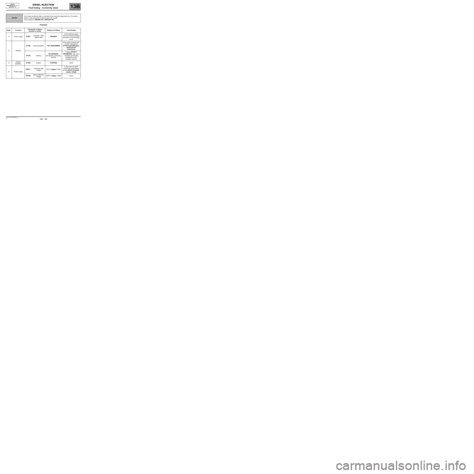
DIESEL INJECTION
Fault finding – Conformity check13B
13B - 150V3 MR-372-J84-13B250$450.mif
EDC16
PROGRAM NO.: C1
Vdiag No.: 51
STARTING
NOTESOnly check conformity after a complete check using the diagnostic tool. The values
shown in this conformity check are given as a guide.
Test conditions: ENGINE OFF, IGNITION ON.
Order FunctionParameter or Status
checked or ActionDisplay and Notes Fault finding
1Power supplyET001:Computer + after
ignition feedPRESENTIn the event of a fault,
carry out a full fault finding
procedure on the charging
circuit.
2StartingET238:SynchronisationNOT PERFORMEDIn the event of a fault, refer
to fault interpretation
DF195 Camshaft/engine
speed sensor
consistency.
ET076:StartingAUTHORISED:
the injection authorises
startingIf status ET076 is
PROHIBITED, carry out a
complete fault finding
procedure on the
multiplex network.
3Engine
operation.ET038:EngineSTOPPEDNone
4Power supplyPR071:Computer feed
voltage9 V < voltage < 16 VIn the event of a fault,
consult the interpretation
of fault DF047 Computer
supply voltage.
PR358:Sensor reference
voltage3.4 V < voltage < 3.8 VNone
Page 163 of 273
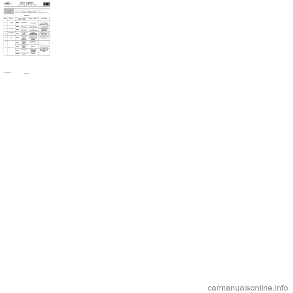
DIESEL INJECTION
Fault finding – Conformity check13B
13B - 163V3 MR-372-J84-13B250$540.mif
EDC16
PROGRAM NO.: C1
Vdiag No.: 51
COLD LOOP
NOTESOnly check conformity after a complete check using the diagnostic tool. The values
shown in this conformity check are given as a guide.
Test Conditions: ENGINE AT IDLE SPEED, COOLANT TEMPERATURE > 80 ˚C.
Order FunctionParameter or Status
checked or ActionDisplay and Notes Fault finding
1EnginePR055:Engine speedGives the engine's
speed in rpmIn the event of a fault, refer
to the interpretation for
fault DF005 Engine
speed sensor circuit.
2Driver controlET088:Compressor
actuation requestACTIVE if air
conditioning requestIf the air conditioning is
authorised or the
compressor is actuated
(see 62A Air
conditioning). ET004:Air conditioning
authorisationYES if air
conditioning request
3Air conditioning
speedPR053:Speed requested
by air
conditioning875 rpm
according to the
computer programThis parameter is only
valid when the engine has
been started
4OutputPR125:Power absorbed
by the air
conditioning
compressorIndicates the power
absorbed by the air
conditioning
compressorThis parameter is only
valid when the engine has
been started
5Engine coolingET021:Low speed fan
assembly
requestACTIVE if air
conditioning request
If the fan assemblies are
supplied with ignition on,
the injection system may
be in defect mode.
Carry out a system fault
test and refer to the
interpretation of any
faults. ET022:High speed fan
assembly
requestINACTIVE
ET014:Monitor cooling
fan 1RUNNING if air
conditioning
requested
ET015:Monitor cooling
fan 2STOPPED