stop start RENAULT SCENIC 2009 J84 / 2.G Engine And Peripherals EDC16 User Guide
[x] Cancel search | Manufacturer: RENAULT, Model Year: 2009, Model line: SCENIC, Model: RENAULT SCENIC 2009 J84 / 2.GPages: 273
Page 175 of 273
DIESEL INJECTION
Fault finding – Interpretation of statuses13B
13B - 175V3 MR-372-J84-13B250$630.mif
NO
EDC16
PROGRAM NO.: C1
Vdiag No.: 51
ET007
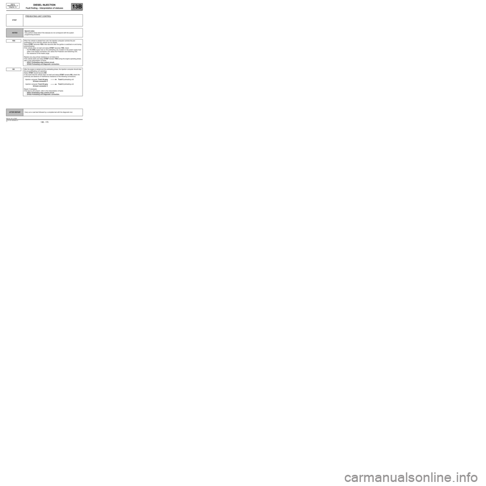
PREHEATING UNIT CONTROL
NOTESSpecial notes:
Only perform these tests if the statuses do not correspond with the system
programming functions.
YES
When the vehicle is started from cold, the injection computer controls the pre-
postheating unit so that the vehicle can be started.
Status ET007 becomes YES a few seconds after the ignition is switched on and during
pre/postheating.
If the vehicle does not start and status ET007 becomes YES, check:
–the F2 (70A) supply fuse on the preheating unit, located on the power supply fuse
plate in the engine connection unit, below the Protection and Switching Unit,
–the resistance of the heater plugs.
Replace any plug whose resistance is not below 2 Ω.
If the vehicle starts and status ET007 remains YES during the engine operating phase,
refer to the interpretation of faults:
–DF017 Preheating relay control circuit.
–DF025 Preheating unit diagnostic connection.
After the engine is started and the preheating phase, the injection computer should stop
the pre-postheating unit operating.
Status ET007 should become NO.
In the event that the vehicle does not start and status ET007 remains NO, check the
continuity and absence of interference resistance of the following connections:
Injection computer Track A4 grey
32-track connector CTrack 9 preheating unit
Injection computer Track E2 grey
32-track connector CTrack 8 preheating unit
Repair if necessary.
If the fault is still present, refer to the interpretation of faults:
–DF017 Preheating relay control circuit.
–DF025 Preheating unit diagnostic connection.
AFTER REPAIRCarry out a road test followed by a complete test with the diagnostic tool.
EDC16_V51_ET007
Page 180 of 273
DIESEL INJECTION
Fault finding – Interpretation of statuses13B
13B - 180V3 MR-372-J84-13B250$630.mif
EDC16
PROGRAM NO.: C1
Vdiag No.: 51
ET038
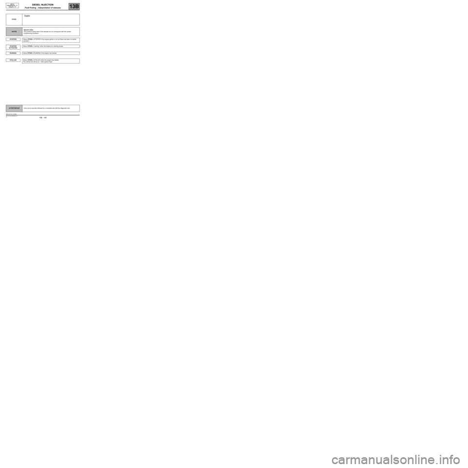
Engine
NOTESSpecial notes:
Only perform these tests if the statuses do not correspond with the system
programming functions.
STOPPED
Status ET038 is STOPPED if the engine ignition is on but there has been no starter
operation.
Status ET038 is “starting” when the engine is in starting phase.
Status ET038 is RUNNING if the engine has started.
Status ET038 is STALLED when the engine has stalled.
The vehicle will still be on + after ignition feed.
STARTER
ACTIVATED
RUNNING
STALLED
AFTER REPAIRCarry out a road test followed by a complete test with the diagnostic tool.
EDC16_V51_ET038
Page 191 of 273
DIESEL INJECTION
Fault finding – Interpretation of statuses13B
13B - 191V3 MR-372-J84-13B250$630.mif
COMPLETED
EDC16
PROGRAM NO.: C1
Vdiag No.: 51
ET238
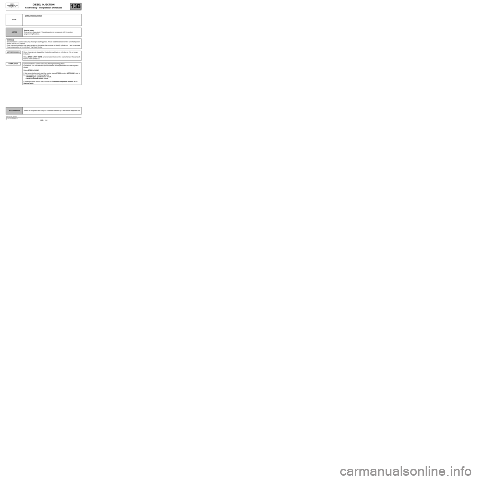
SYNCHRONISATION
NOTESSpecial notes:
Only perform these tests if the statuses do not correspond with the system
programming functions.
WARNING
Synchronisation is carried out during the engine starting phase. This is established between the camshaft position
sensor and the TDC sensor.
Once this synchronisation has been carried out, it enables the computer to identify cylinder no. 1 and to calculate
the precise position of the cylinder's Top Dead Centre.
NOT PERFORMED
When the engine is stopped but the ignition switched on, cylinder no. 1 is no longer
indicated.
Status ET238 is NOT DONE; synchronisation between the crankshaft and the camshaft
has not been carried out.
Synchronisation is carried out during the engine starting phase.
Cylinder No. 1 is indicated and synchronisation will be performed once the engine is
started.
Status ET238 is DONE.
If after several attempts to start the engine, status ET238 remains NOT DONE, refer to
the interpretation of the following faults:
–DF005 Engine speed sensor circuit.
–DF097 Camshaft sensor circuit.
If the engine does still not start, consult the Customer complaints section, ALP2
Starting faults.
AFTER REPAIRSwitch off the ignition and carry out a road test followed by a test with the diagnostic tool
EDC16_V51_ET238
Page 201 of 273
DIESEL INJECTION
Fault finding – Interpretation of statuses13B
13B - 201V3 MR-372-J84-13B250$630.mif
STATUS 18
STATUS 20
STATUS 21
STATUS 11, 22
STATUS 8
STATUS 4, 17
STATUS 2
STATUS 3, 14, 16
STATUSES 1, 5, 6,
7, 9, 10, 12, 13, 15,
19, 23, 24
EDC16
PROGRAM NO.: C1
Vdiag No.: 51
ET651
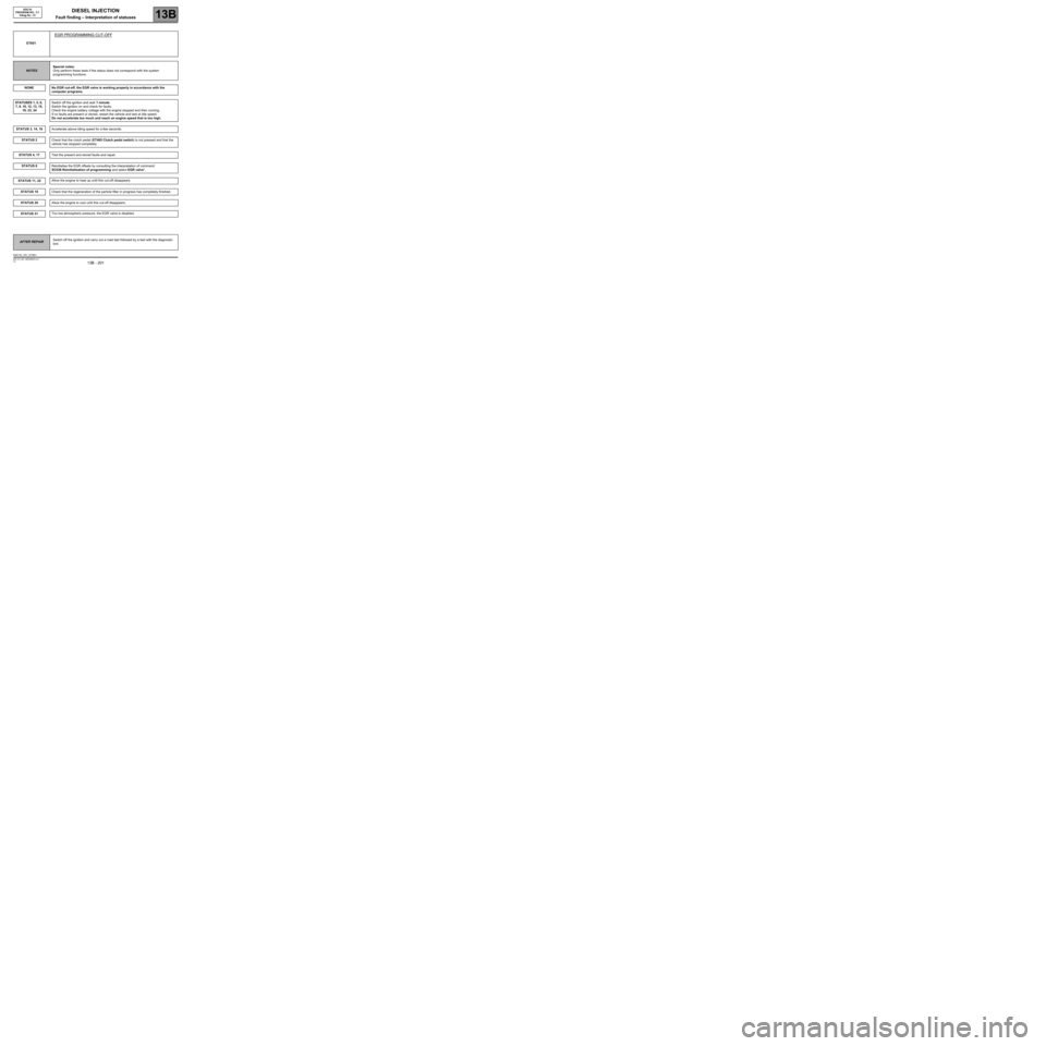
EGR PROGRAMMING CUT-OFF
NOTESSpecial notes:
Only perform these tests if the status does not correspond with the system
programming functions.
NONE
No EGR cut-off, the EGR valve is working properly in accordance with the
computer programs.
Switch off the ignition and wait 1 minute.
Switch the ignition on and check for faults.
Check the engine battery voltage with the engine stopped and then running.
If no faults are present or stored, restart the vehicle and test at idle speed.
Do not accelerate too much and reach an engine speed that is too high.
Accelerate above idling speed for a few seconds.
Check that the clutch pedal (ET405 Clutch pedal switch) is not pressed and that the
vehicle has stopped completely.
Test the present and stored faults and repair.
Reinitialise the EGR offsets by consulting the interpretation of command
SC036 Reinitialisation of programming and select EGR valve".
Allow the engine to heat up until this cut-off disappears.
Check that the regeneration of the particle filter in progress has completely finished.
Allow the engine to cool until this cut-off disappears.
Too low atmospheric pressure, the EGR valve is disabled.
AFTER REPAIRSwitch off the ignition and carry out a road test followed by a test with the diagnostic
tool.
EDC16_V51_ET651
Page 216 of 273
DIESEL INJECTION
Fault finding – Interpretation of commands13B
13B -216V3 MR-372-J84-13B250$765.mif
EDC16
PROGRAM No: C1
Vdiag No.: 51
AC004
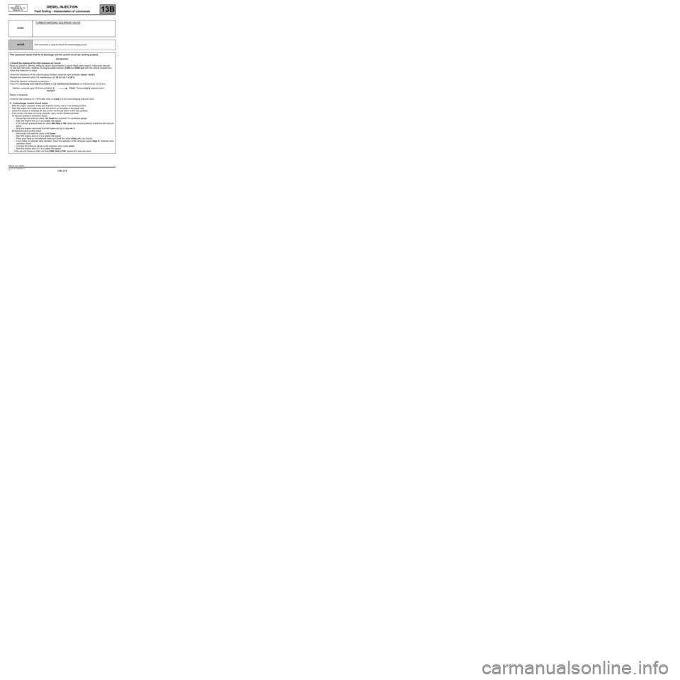
TURBOCHARGING SOLENOID VALVE
NOTESThis command is used to check the turbocharging circuit.
This command checks that the turbocharger and the control circuit are working properly.
Introduction
1-Check the sealing of the high pressure air circuit:
Pipes not joined or pierced, pressure sensor disconnected or poorly fitted (seal present), intercooler pierced.
To test the intercooler: stabilise the engine speed between 3,500 and 4,000 rpm with the vehicle stopped and
check that there are no leaks.
Check the resistance of the turbocharging limitation solenoid valve between tracks 1 and 2.
Replace the solenoid valve if its resistance is not 15.4 Ω ± 0.7 at 20˚C.
Check the injection computer connections.
Check for continuity and make sure there is no interference resistance on the following connection:
Injection computer grey 32-track connector C,
track E1Track 1 turbocharging solenoid valve
Repair if necessary.
Check for the presence of + 12 V after relay on track 2 of the turbocharging solenoid valve.
2 - Turbocharger control circuit check
–With the engine stopped, make sure that the control rod is in the resting position.
–Start the engine and make sure that the control rod actuates to the upper stop.
–(when the engine is switched off, the control rod should return to the rest position)
–If the control rod does not move correctly, carry out the following checks:
1) Vacuum pressure command check:
–Disconnect the solenoid valve inlet hose and connect it to a pressure gauge.
–Start the engine and run it at a stable idle speed.
–If the vacuum pressure does not reach 800 mbar ± 100: check the vacuum pressure circuit from the vacuum
pump.
–Stop the engine, reconnect the inlet hoses and go to step no. 2.
2) Solenoid valve control check:
–Disconnect the solenoid valve outlet hose.
–Start the engine and run it at a stable idle speed.
–Place your hand on the solenoid valve and block the outlet union with your thumb.
–If you notice no solenoid valve vibration, check the operation of the computer output (step 5). Solenoid valve
operation check:
–Connect the pressure gauge to the solenoid valve outlet union.
–Start the engine and run it at a stable idle speed.
If the vacuum pressure does not reach 800 mbar ± 100, replace the solenoid valve.
EDC16_V51_AC004
Page 231 of 273
DIESEL INJECTION
Fault finding – Fault Finding Chart13B
13B -231V3 MR-372-J84-13B250$855.mif
EDC16
PROGRAM No.: C1
Vdiag No.: 51
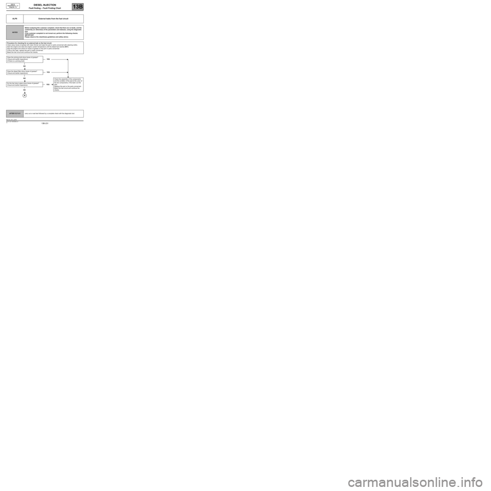
ALP6 External leaks from the fuel circuit
NOTESBefore analysing this customer complaint, check that there are no faults, and the
conformity (or otherwise) of the parameters and statuses, using the diagnostic
tool.
If the customer complaint is not ironed out, perform the following checks:
IMPORTANT
Please observe the cleanliness guidelines and safety advice.
Procedure for checking for an external leak on the fuel circuit:
Clean away traces of grease with clean thinner and wipe the part or parts concerned with cleaning cloths.
Start the engine and raise the engine coolant temperature until the diesel fuel reaches 80˚C.
Stop the engine and check for traces of grease on the part or parts concerned.
If this is the case, replace the part or parts concerned.
Bleed the fuel circuit and continue the checks.
Does the priming bulb show traces of grease?
(Visual and tactile inspections)
(If there is a priming bulb)YES
NO
Does the diesel filter show traces of grease?
(Visual and tactile inspections)YES
NO
Do the fuel return pipes show traces of grease?
(Visual and tactile inspections)
NO
YESCheck the assembly of the components
and the condition of the seal at the union of
the two components, if the leak is at the
seal.
Replace the part or the parts concerned.
Bleed the fuel circuit and continue the
checks.
AFTER REPAIRcarry out a road test followed by a complete check with the diagnostic tool.
EDC16_V51_ALP6
Page 241 of 273
DIESEL INJECTION
Fault finding – Test13B
13B -241V3 MR-372-J84-13B250$900.mif
EDC16
PROGRAM No.: C1
Vdiag No.: 51
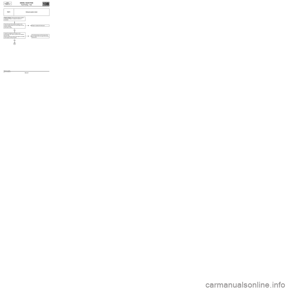
TEST1 Exhaust system check
Engine stopped: Check that the silencer outlet is
not blocked. Repair or replace the silencer, if
necessary.
Check the seal of the exhaust manifold on the
contact surface between the turbocharger and the
exhaust manifold.
Is the seal in order?
YES
Loosen the catalytic pre-converter on the
turbocharger side. Place a wooden block between
the two parts.
Start the vehicle and check if the engine runs better.
Is the engine running normally?
YES
NORepair or replace the faulty part.
NOThe exhaust pipe is not the cause of the
fault. Continue with the engine fault finding
(see ALP5).
EDC16_V51_TEST1