change time RENAULT SCENIC 2009 J84 / 2.G Engine And Peripherals EDC16 Workshop Manual
[x] Cancel search | Manufacturer: RENAULT, Model Year: 2009, Model line: SCENIC, Model: RENAULT SCENIC 2009 J84 / 2.GPages: 273
Page 176 of 273
DIESEL INJECTION
Fault finding – Interpretation of statuses13B
13B - 176V3 MR-372-J84-13B250$630.mif
EDC16
PROGRAM NO.: C1
Vdiag No.: 51
ET014
CHECK COOLING FAN 1
NOTESSpecial notes:
Only perform these tests if the statuses do not correspond with the system
programming functions.
NOTE:
Status ET014 test and status ET022 GMV1 low speed request change their status at the same time.
RUNNING
The low-speed engine fan unit is supplied in three scenarios:
–the engine coolant temperature is above 89 ˚C;
–the air conditioning is operating
–the injection computer has system faults that could lead to the engine overheating.
When the low-speed engine fan is supplied:
–status ET014 GMV 1 test becomes RUNNING status ET022 Low speed GMV
request becomes ACTIVE.
If the low speed GMV does not work (see 87G, engine compartment connection unit).
The low-speed engine fan assembly stops when:
–the engine coolant temperature is below 89 ˚C;
–the air conditioning is not switched on by the driver.
STOPPED
IMPORTANTWARNING
If the UPC does not detect the injection computer frames, the low speed engine
fan is supplied until the battery is completely discharged.
In the event that the low-speed engine fan assembly is faulty, the high-speed
engine fan assembly will then be activated.
AFTER REPAIRCarry out a road test followed by a complete test with the diagnostic tool.
EDC16_V51_ET014
Page 177 of 273
DIESEL INJECTION
Fault finding – Interpretation of statuses13B
13B - 177V3 MR-372-J84-13B250$630.mif
STOPPED
EDC16
PROGRAM NO.: C1
Vdiag No.: 51
ET015
CHECK COOLING FAN 2
NOTESSpecial notes:
Only perform these tests if the statuses do not correspond with the system
programming functions.
NOTE:
Status ET015 GMV 2 test and status ET021 High speed GMV request change their status at the same time.
RUNNING
The engine fan assembly can be supplied when:
–the engine coolant temperature is above 99 ˚C.
–the injection computer has system faults that could lead to the engine overheating.
When the high speed fan is supplied:
–status ET015 GMV 2 test becomes RUNNING and status ET021 High speed GMV
request becomes ACTIVE.
The high-speed engine fan assembly stops when:
–the engine coolant temperature is below 99 ˚C;
IMPORTANTWARNING
If the UPC does not detect the injection computer frames, the low speed engine
fan is supplied until the battery is completely discharged.
In the event that the low-speed engine fan assembly is faulty, the high-speed
engine fan assembly will then be activated.
AFTER REPAIRCarry out a road test followed by a complete test with the diagnostic tool.
EDC16_V51_ET015
Page 178 of 273
DIESEL INJECTION
Fault finding – Interpretation of statuses13B
13B - 178V3 MR-372-J84-13B250$630.mif
INACTIVE
EDC16
PROGRAM NO.: C1
Vdiag No.: 51
ET021
HIGH-SPEED FAN REQUEST
NOTESSpecial notes:
Only perform these tests if the statuses do not correspond with the system
programming functions.
NOTE:
Status ET021 High speed GMV request and status ET015 GMV 2 test change their status at the same time.
ACTIVE
The injection computer requests the activation of the high speed GMV when:
–the engine coolant temperature is above 99 ˚C.
–the injection computer has system faults that could lead to the engine overheating.
When the high speed fan is supplied:
–status ET021 High speed GMV request becomes RUNNING and status ET015
GMV 2 test becomes ACTIVE.
The high-speed engine fan assembly stops when:
–the engine coolant temperature is below 99 ˚C;
–no fault which could cause engine overheating is present in the injection
system.
IMPORTANTWARNING
If the UPC does not detect the injection computer frames, the low speed engine
fan is supplied until the battery is completely discharged.
In the event that the low-speed engine fan assembly is faulty, the high-speed
engine fan assembly will then be activated.
AFTER REPAIRCarry out a road test followed by a complete test with the diagnostic tool.
EDC16_V51_ET021
Page 179 of 273
DIESEL INJECTION
Fault finding – Interpretation of statuses13B
13B - 179V3 MR-372-J84-13B250$630.mif
INACTIVE
EDC16
PROGRAM NO.: C1
Vdiag No.: 51
ET022
LOW SPEED GMV CONTROL
NOTESSpecial notes:
Only perform these tests if the statuses do not correspond with the system
programming functions.
NOTE:
Status ET022 Low speed GMV request and status ET014 GMV 1 test change their status at the same time.
ACTIVE
The injection computer requests the activation of the low speed GMV when:
–the engine coolant temperature is above 89 ˚C;
–the injection computer has system faults that could lead to the engine overheating,
–the air conditioning is switched on by the driver.
When the high speed fan is supplied:
–status ET022 Low speed GMV request becomes ACTIVE and status ET014 GMV
1 test becomes RUNNING.
The low-speed engine fan assembly stops when:
–the engine coolant temperature is below 89 ˚C;
–no fault which could cause engine overheating is present in the injection
system.
–the air conditioning is not switched on by the driver.
IMPORTANTWARNING
If the UPC does not detect the injection computer frames, the low speed engine
fan is supplied until the battery is completely discharged.
In the event that the low-speed engine fan assembly is faulty, the high-speed
engine fan assembly will then be activated.
AFTER REPAIRCarry out a road test followed by a complete test with the diagnostic tool.
EDC16_V51_ET022
Page 196 of 273
DIESEL INJECTION
Fault finding – Interpretation of statuses13B
13B - 196V3 MR-372-J84-13B250$630.mif
EDC16
PROGRAM NO.: C1
Vdiag No.: 51
1
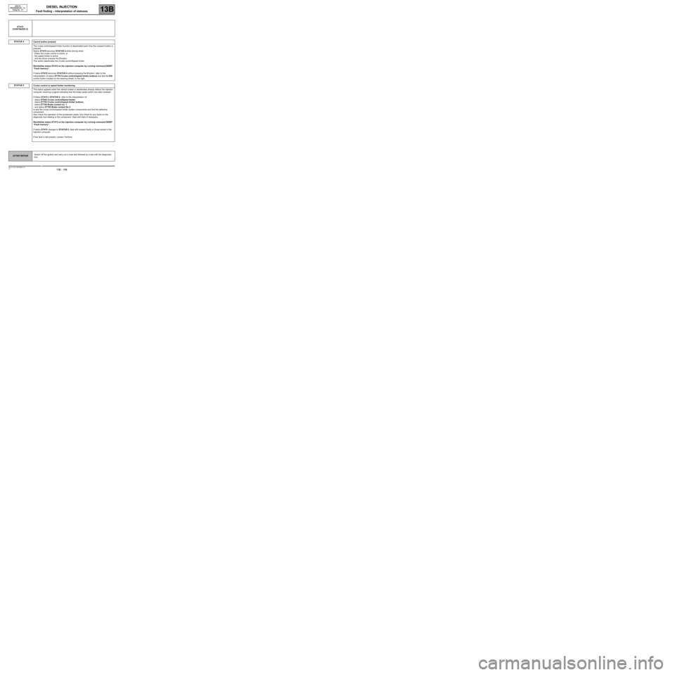
STATUS 5
ET415
(CONTINUED 2)
STATUS 4
Cancel button pressed
The cruise control/speed limiter function is deactivated each time the suspend button is
pressed.
Status ET415 becomes STATUS 4 while driving when:
- Either the cruise control is active, or
- the speed limiter is active
- and the driver presses the 0 button.
This action deactivates the Cruise control/Speed limiter.
Reinitialise status ET415 on the injection computer by running command RZ007
“Fault memory”.
If status ET415 becomes STATUS 4 without pressing the 0 button, refer to the
interpretation of status ET703 Cruise control/speed limiter buttons and test the R/0
control button located on the steering wheel, to the right.
Cruise control or speed limiter monitoring
This status appears when the vehicle brakes or decelerates sharply without the injection
computer receiving a signal indicating that the brake pedal switch has been pressed.
If status ET415 is STATUS 5, refer to the interpretation of:
- status ET042 Cruise control/Speed limiter,
- status ET703 Cruise control/speed limiter buttons,
- status ET704 Brake contact no. 1,
- and status ET705 Brake contact No 2,
to test the cruise control/speed limiter system components and find the defective
component.
Also check the operation of the accelerator pedal, and check for any faults on the
diagnostic tool relating to this component. Deal with them if necessary.
Reinitialise status ET415 on the injection computer by running command RZ007
“Fault memory”.
If status ET415 changes to STATUS 5, deal with present faults or those stored in the
injection computer.
If the fault is still present, contact Techline.
AFTER REPAIRSwitch off the ignition and carry out a road test followed by a test with the diagnostic
tool.
Page 205 of 273
DIESEL INJECTION
Fault finding – Interpretation of statuses13B
13B - 205V3 MR-372-J84-13B250$630.mif
EDC16
PROGRAM NO.: C1
Vdiag No.: 51
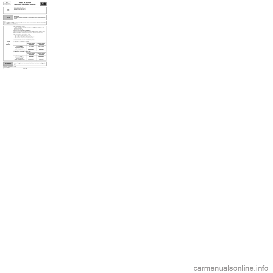
ET704
ET705
BRAKE CONTACT No. 1
BRAKE CONTACT No. 2
NOTESSpecial note:
Only perform the tests if the statuses do not correspond with the system programming
functions.
Note:
Statuses ET704 and ET705 should change at the same time. If they are not consistent, refer to the interpretation
of fault DF050 Brake switch circuit.
ACTIVE
or
INACTIVEIf the brake lights are working:
–check the continuity and make sure there is no interference resistance on the
following connection:
●connection code 5A,
between components 160 and 120/645/119.
If there is a repair method (See Technical Note 6015A, Repairing electrical wiring,
Wiring: Precautions for repair), repair the wiring, otherwise replace the wiring.
If the brake lights are not operational, check:
–the condition and fitting of the brake switch,
–the condition and conformity of the brake lights fuse,
–the conformity of the values in the following table:
disconnect the switch and carry out the following checks:
for MEGANE II and SCENIC II with ESP:
Continuity between
connectionsInsulation between
connections
Switch engaged
(Brake pedal released)5A and BPT 65G and SP17
Switch released
(Brake pedal depressed)65G and SP17 5A and BPT
For MEGANE II and SCENIC II without ESP
Continuity between
connectionsInsulation between
connections
Switch engaged
(Brake pedal released)5A and BPT 65A and SP17
Switch released
(Brake pedal depressed)65G and SP17 5A and BPT
AFTER REPAIRSwitch off the ignition and carry out a road test followed by a test with the diagnostic
tool.
EDC16_V51_ET704/EDC16_V51_ET705
Page 232 of 273
DIESEL INJECTION
Fault finding – Fault Finding Chart13B
13B -232V3 MR-372-J84-13B250$855.mif
EDC16
PROGRAM No.: C1
Vdiag No.: 51
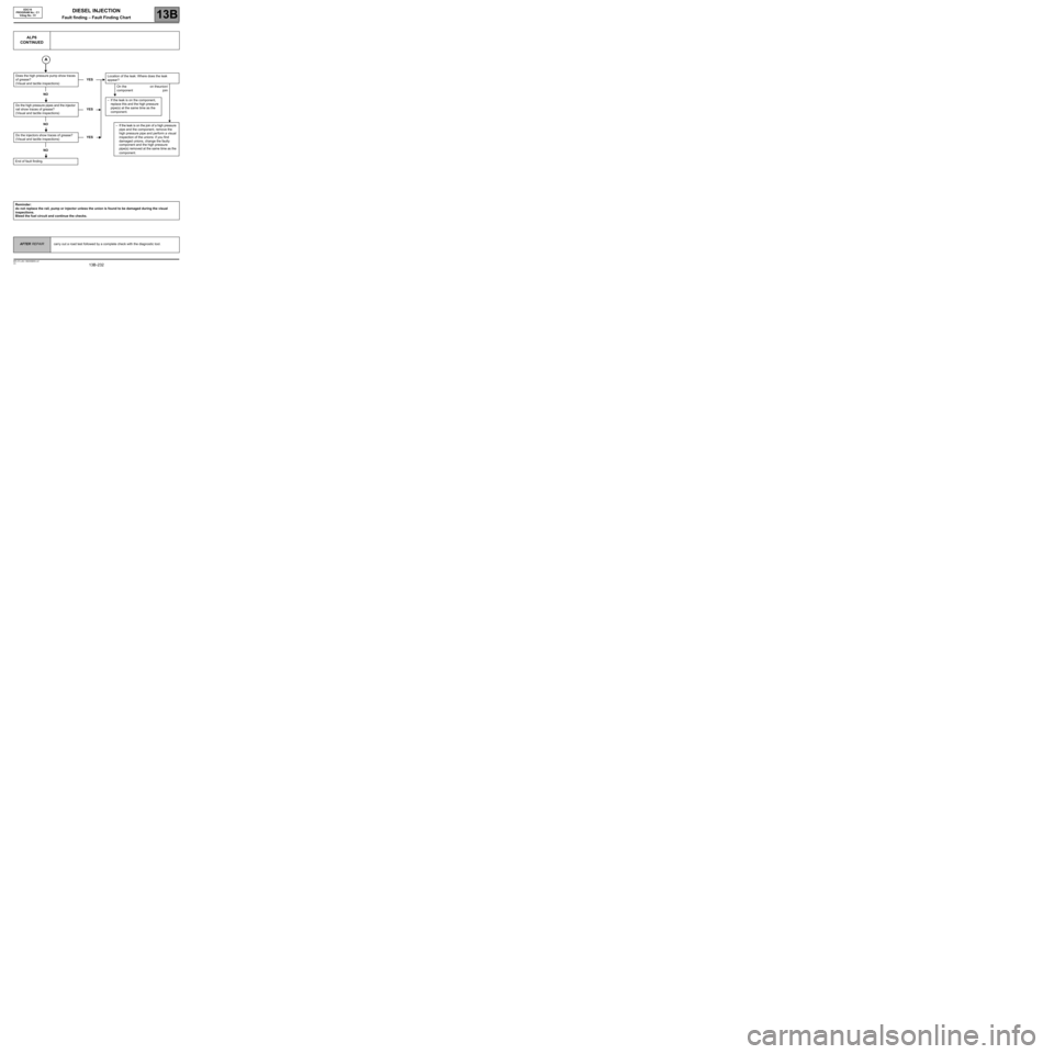
ALP6
CONTINUED
Does the high pressure pump show traces
of grease?
(Visual and tactile inspections)YES
NO
Do the high pressure pipes and the injector
rail show traces of grease?
(Visual and tactile inspections)YES
NO
Do the injectors show traces of grease?
(Visual and tactile inspections)YES
NO
End of fault finding.Location of the leak: Where does the leak
appear?
On the
componenton theunion/
join
–If the leak is on the component,
replace this and the high pressure
pipe(s) at the same time as the
component.
–If the leak is on the join of a high pressure
pipe and the component, remove the
high pressure pipe and perform a visual
inspection of the unions: if you find
damaged unions, change the faulty
component and the high pressure
pipe(s) removed at the same time as the
component.
Reminder:
do not replace the rail, pump or injector unless the union is found to be damaged during the visual
inspections.
Bleed the fuel circuit and continue the checks.
AFTER REPAIRcarry out a road test followed by a complete check with the diagnostic tool.