wire RENAULT SCENIC 2009 J84 / 2.G Engine And Peripherals EDC16 Workshop Manual
[x] Cancel search | Manufacturer: RENAULT, Model Year: 2009, Model line: SCENIC, Model: RENAULT SCENIC 2009 J84 / 2.GPages: 273
Page 3 of 273

DIESEL INJECTION
Fault finding – Introduction13B
13B - 3V3 MR-372-J84-13B250$045.mif
EDC16
PROGRAM No: C1
Vdiag No.: 51
Faults
Faults are declared as either present or stored (depending on whether they appeared in a certain context and have
disappeared since, or whether they remain present but have not been diagnosed within the current context).
The present or stored status of faults should be taken into consideration when the diagnostic tool is switched on
after the + after ignition feed (without any system components being active).
For a present fault, apply the procedure described in the Interpretation of faults section.
For a stored fault, note the faults displayed and apply the instructions in the Notes section.
If the fault is confirmed when the instructions in the Notes section are applied, the fault is present. Deal with the fault
If the fault is not confirmed, check:
–the electrical lines which correspond to the fault,
–the connectors for these lines (for oxidation, bent pins, etc.),
–the resistance of the component detected as faulty,
–the condition of the wires (melted or split insulation, wear).
Conformity check
The aim of the conformity check is to check data that does not produce a fault on the diagnostic tool because the
data is inconsistent. Therefore, this stage is used to:
–carry out fault finding on faults that do not have a fault display, and which may correspond to a customer
complaint.
–check that the system is operating correctly and that there is no risk of a fault recurring after repairs.
This section gives the fault finding procedures for statuses and parameters and the conditions for checking them.
If a status is not behaving normally or a parameter is outside the permitted tolerance values, consult the
corresponding fault finding page.
Customer complaints - Fault finding chart
If the test with the diagnostic tool is OK but the customer complaint is still present, the fault should be processed by
customer complaints.
A synopsis of the general procedure to follow is provided on the following page in
the form of a flow chart
Page 5 of 273

DIESEL INJECTION
Fault finding – Introduction13B
13B - 5V3 MR-372-J84-13B250$045.mif
EDC16
PROGRAM No: C1
Vdiag No.: 51
FAULT FINDING PROCEDURE (continued)
Wiring check
Fault finding problems
Disconnecting the connectors and/or manipulating the wiring harness may temporarily remove the cause of a fault.
Electrical measurements of voltage, resistance and insulation are generally correct, especially if the fault is not
present when the analysis is made (stored fault).
Visual inspection
Look for damage under the bonnet and in the passenger compartment.
Carefully check the fuses, insulators and wiring harness routing.
Look for signs of oxidation.
Tactile inspection
While manipulating the wiring harness, use the diagnostic tool to note any change in fault status from stored to
present.
Make sure that the connectors are properly locked.
Apply light pressure to the connectors.
Twist the wiring harness.
If there is a change in status, try to locate the source of the fault.
Inspection of each component
Disconnect the connectors and check the appearance of the clips and tabs, as well as the crimping (no crimping on
the insulating section).
Make sure that the clips and tabs are properly locked in the sockets.
Check that no clips or tabs have been dislodged during connection.
Check the clip contact pressure using an appropriate model of tab.
Resistance check
Check the continuity of entire lines, then section by section.
Look for a short circuit to earth, to + 12 V or to another wire.
If a fault is detected, repair or replace the wiring harness.
Page 11 of 273

DIESEL INJECTION
Fault finding – System operation13B
13B - 11V3 MR-372-J84-13B250$135.mif
EDC16
PROGRAM No: C1
Vdiag No.: 51
b) Multiplex connection between the different vehicle computers.
The electronic system fitted in this vehicle is multiplexed.
This enables dialogue between the various vehicle computers. As a result:
–the activation of the fault warning lights on the instrument panel is performed by the multiplex network, with the
vehicle speed sensor on the gearbox deactivated,
–vehicle faults are displayed by the multiplex network,
–the vehicle speed sensor on the gearbox is not needed.
The vehicle speed signal on the instrument panel is transmitted by the ABS computer via a wire connection, then
sent out on the multiplex network by the instrument panel. The vehicle speed signal is used mainly by the injection
computer and the airbag computer.
Some vehicles have adopted a sensor for detecting water in the diesel fuel, located in the filter. If there is water in the
diesel fuel, the orange "Injection and pre-post heating" warning light will come on.
The system can inject diesel fuel into the engine at a pressure of up to 1600 bar. Before each operation, check that
the injector rail is depressurised and that the fuel temperature is not too high.
You must respect the cleanliness guidelines and safety advice specified in this document for any work on the high
pressure injection system.
Removal of the internal parts of the pump and injectors is prohibited. Only the fuel flow actuator, the diesel fuel
temperature sensor and the venturi can be replaced.
For safety reasons, it is strictly prohibited to undo a high pressure pipe union when the engine is running.
It is not possible to remove the pressure sensor from the fuel rail because this may cause circuit contamination
faults. If the pressure sensor fails, the pressure sensor, the rail and the five high pressure pipes must be replaced.
It is forbidden to remove any injection pump pulley bearing the number 070 575. If the pump needs to be replaced,
replace the pulley.
Supplying + 12 V directly to any component in the system is prohibited.
Ultrasonic decoking and cleaning are prohibited.
Never start the engine unless the battery is connected correctly.
Disconnect the injection computer when carrying out any welding work on the vehicle.WARNING
The engine must not operate with:
–Diesel fuel containing more than 10 % diester,
–petrol, even in tiny quantities.
Page 250 of 273

DIESEL INJECTION
Fault finding – Test13B
13B -250V3 MR-372-J84-13B250$900.mif
EDC16
PROGRAM No.: C1
Vdiag No.: 51
TEST5
CONTINUED 2
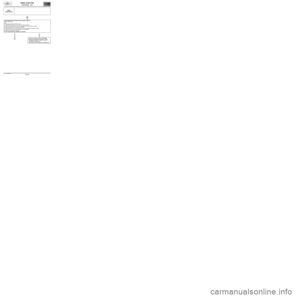
Visual inspection of the solenoid valve electrical connector
Switch off the engine.
Note:
The requested checks are entirely visual.
1- Check that the connector is correctly connected and locked.
2- Check that the electric wires are not damaged where they leave the insulation.
Disconnect the connector to continue the checks.
3- Check that there is no heat damage to the unit and mechanical damage to the lock.
4- Check that the contacts (clips and tabs) are not deformed.
5- Check the sealing of the connector.
Do the visual inspections highlight any damage?
NO YES
If there is a repair procedure (see Technical
Note 6015A, Electrical wiring repair, Wiring:
Precautions for repair), repair the connector,
otherwise replace the wiring.
After repair, restart the test from the beginning.
C
1