ABS RENAULT SCENIC 2010 J95 / 3.G Petrol Injection S3000 Injection User Guide
[x] Cancel search | Manufacturer: RENAULT, Model Year: 2010, Model line: SCENIC, Model: RENAULT SCENIC 2010 J95 / 3.GPages: 230, PDF Size: 0.92 MB
Page 66 of 230

PETROL INJECTION
Fault finding - Interpretation of faults
17B
17B-66
PETROL INJECTION
Fault finding - Interpretation of faults
17B
17B-66V9 MR-372-J84-17B050$376.mif
S3000 Injection
Program No.: AD
Vdiag No.: 4C / 54
DF081
CONTINUED
Disconnect the battery.
Disconnect the computer. Check the cleanliness and condition of the connections.
Use the "Universal bornier" to check the insulation and continuity on the following connection:
Computer, connectorC, track E1 track 2 of the petrol vapour absorber bleed
solenoid valve
Repair if necessary.
If the fault is still present, deal with the other faults then proceed with the conformity check.
AFTER REPAIRFollow the instructions to confirm repair.
Deal with any other faults.
Clear the stored faults.
Page 67 of 230
PETROL INJECTION
Fault finding - Interpretation of faults
17B
17B-67
PETROL INJECTION
Fault finding - Interpretation of faults
17B
17B-67V9 MR-372-J84-17B050$376.mif
S3000 Injection
Program No.: AD
Vdiag No.: 4C / 54
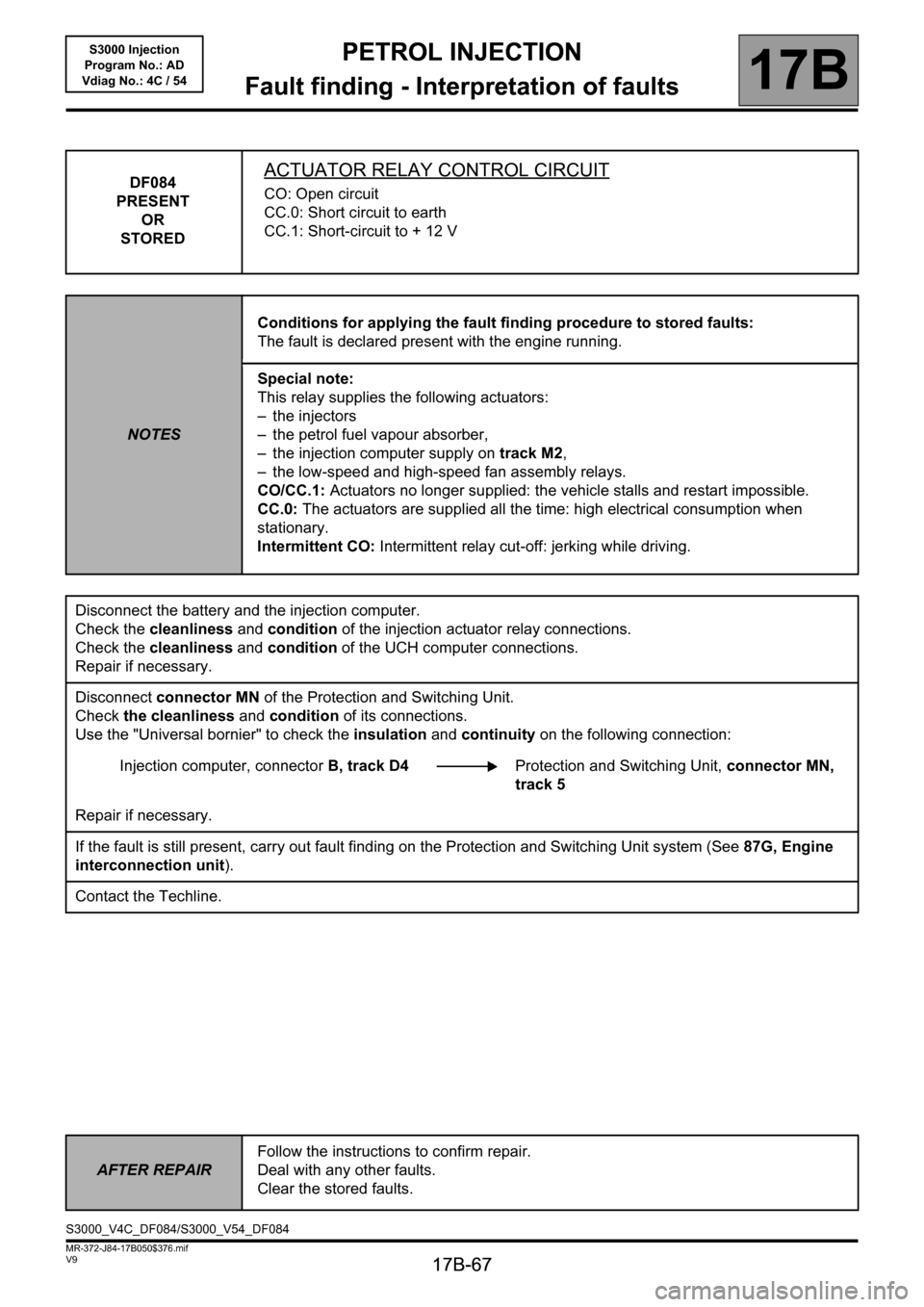
DF084
PRESENT
OR
STOREDACTUATOR RELAY CONTROL CIRCUIT
CO: Open circuit
CC.0: Short circuit to earth
CC.1: Short-circuit to + 12 V
NOTESConditions for applying the fault finding procedure to stored faults:
The fault is declared present with the engine running.
Special note:
This relay supplies the following actuators:
– the injectors
– the petrol fuel vapour absorber,
– the injection computer supply on track M2,
– the low-speed and high-speed fan assembly relays.
CO/CC.1: Actuators no longer supplied: the vehicle stalls and restart impossible.
CC.0: The actuators are supplied all the time: high electrical consumption when
stationary.
Intermittent CO: Intermittent relay cut-off: jerking while driving.
Disconnect the battery and the injection computer.
Check the cleanliness and condition of the injection actuator relay connections.
Check the cleanliness and condition of the UCH computer connections.
Repair if necessary.
Disconnect connector MN of the Protection and Switching Unit.
Check the cleanliness and condition of its connections.
Use the "Universal bornier" to check the insulation and continuity on the following connection:
Injection computer, connectorB, track D4Protection and Switching Unit, connector MN,
track 5
Repair if necessary.
If the fault is still present, carry out fault finding on the Protection and Switching Unit system (See87G, Engine
interconnection unit).
Contact the Techline.
AFTER REPAIRFollow the instructions to confirm repair.
Deal with any other faults.
Clear the stored faults.
S3000_V4C_DF084/S3000_V54_DF084
Page 72 of 230

PETROL INJECTION
Fault finding - Interpretation of faults
17B
17B-72
PETROL INJECTION
Fault finding - Interpretation of faults
17B
17B-72V9 MR-372-J84-17B050$376.mif
S3000 Injection
Program No.: AD
Vdiag No.: 4C / 54
DF091
PRESENT
OR
STOREDVEHICLE SPEED SIGNAL
1.DEF: Multiplex network
2.DEF: Non-compliance with emission control standards
NOTESConditions for applying the fault finding procedure to stored faults:
The fault is declared present with the engine running.
Special note:
–OBD warning light illuminated.
Run a multiplex network test (see88B, Multiplexing).
Disconnect the battery and the injection computer.
Check the cleanliness and condition of the battery and the injection computer connections.
Repair if necessary.
If the fault is still present, carry out fault finding on the ABS - ESP system (see38C, Anti-lock braking system).
AFTER REPAIRFollow the instructions to confirm repair.
Deal with any other faults.
Clear the stored faults.
S3000_V4C_DF091/S3000_V54_DF091
Page 78 of 230
PETROL INJECTION
Fault finding - Interpretation of faults
17B
17B-78
PETROL INJECTION
Fault finding - Interpretation of faults
17B
17B-78V9 MR-372-J84-17B050$376.mif
S3000 Injection
Program No.: AD
Vdiag No.: 4C / 54
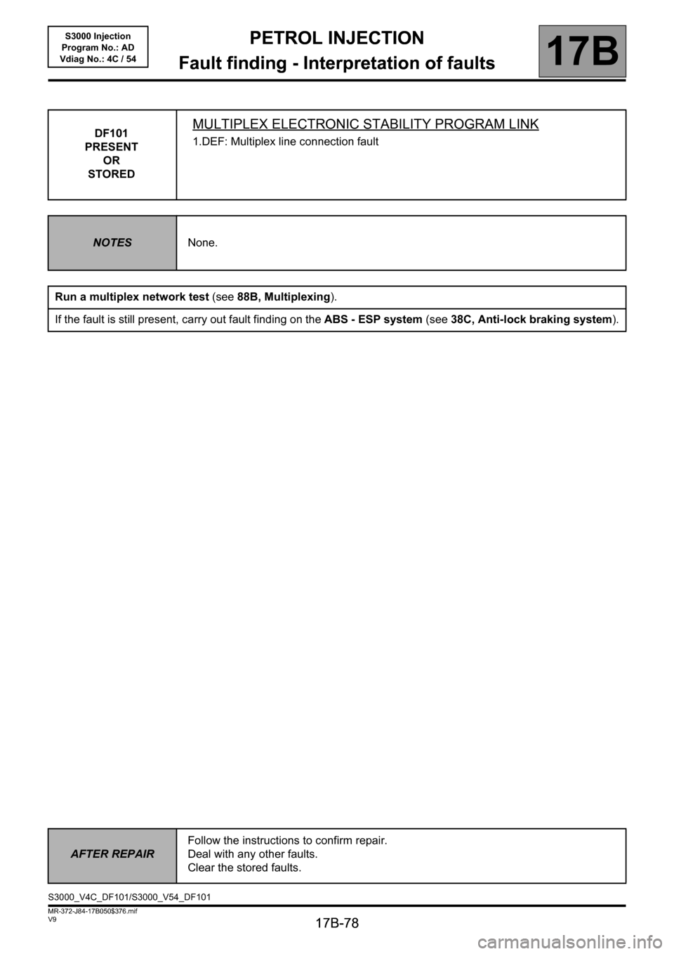
DF101
PRESENT
OR
STOREDMULTIPLEX ELECTRONIC STABILITY PROGRAM LINK
1.DEF: Multiplex line connection fault
NOTESNone.
Run a multiplex network test (see88B, Multiplexing).
If the fault is still present, carry out fault finding on the ABS - ESP system (see38C, Anti-lock braking system).
AFTER REPAIRFollow the instructions to confirm repair.
Deal with any other faults.
Clear the stored faults.
S3000_V4C_DF101/S3000_V54_DF101
Page 79 of 230
PETROL INJECTION
Fault finding - Interpretation of faults
17B
17B-79
PETROL INJECTION
Fault finding - Interpretation of faults
17B
17B-79V9 MR-372-J84-17B050$376.mif
S3000 Injection
Program No.: AD
Vdiag No.: 4C / 54
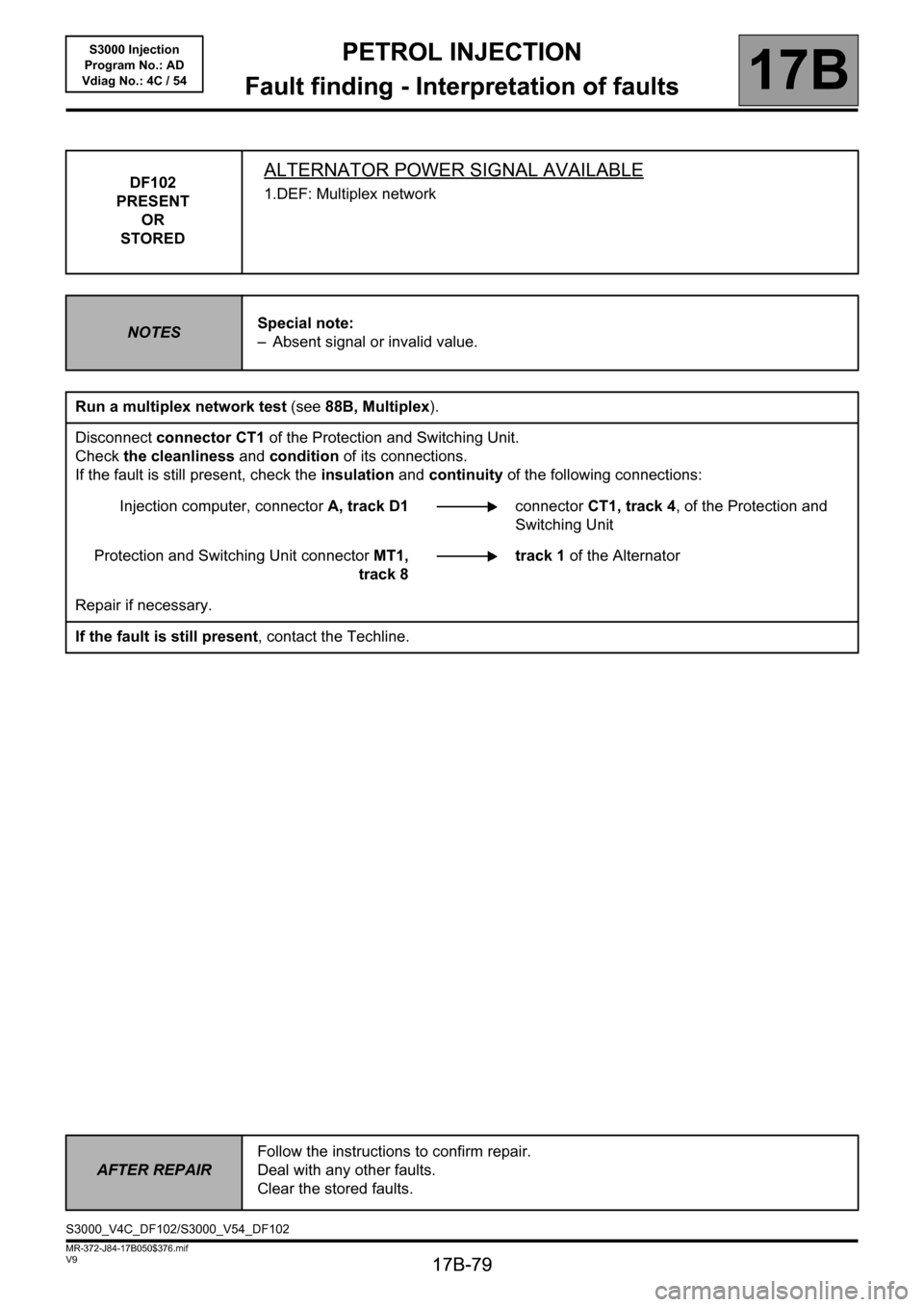
DF102
PRESENT
OR
STOREDALTERNATOR POWER SIGNAL AVAILABLE
1.DEF: Multiplex network
NOTESSpecial note:
– Absent signal or invalid value.
Run a multiplex network test (see88B, Multiplex).
Disconnect connector CT1 of the Protection and Switching Unit.
Check the cleanliness and condition of its connections.
If the fault is still present, check the insulation and continuity of the following connections:
Injection computer, connectorA, track D1connectorCT1, track 4, of the Protection and
Switching Unit
Protection and Switching Unit connectorMT1,
track 8track 1 of the Alternator
Repair if necessary.
If the fault is still present, contact the Techline.
AFTER REPAIRFollow the instructions to confirm repair.
Deal with any other faults.
Clear the stored faults.
S3000_V4C_DF102/S3000_V54_DF102
Page 83 of 230
PETROL INJECTION
Fault finding - Interpretation of faults
17B
17B-83
PETROL INJECTION
Fault finding - Interpretation of faults
17B
17B-83V9 MR-372-J84-17B050$376.mif
S3000 Injection
Program No.: AD
Vdiag No.: 4C / 54
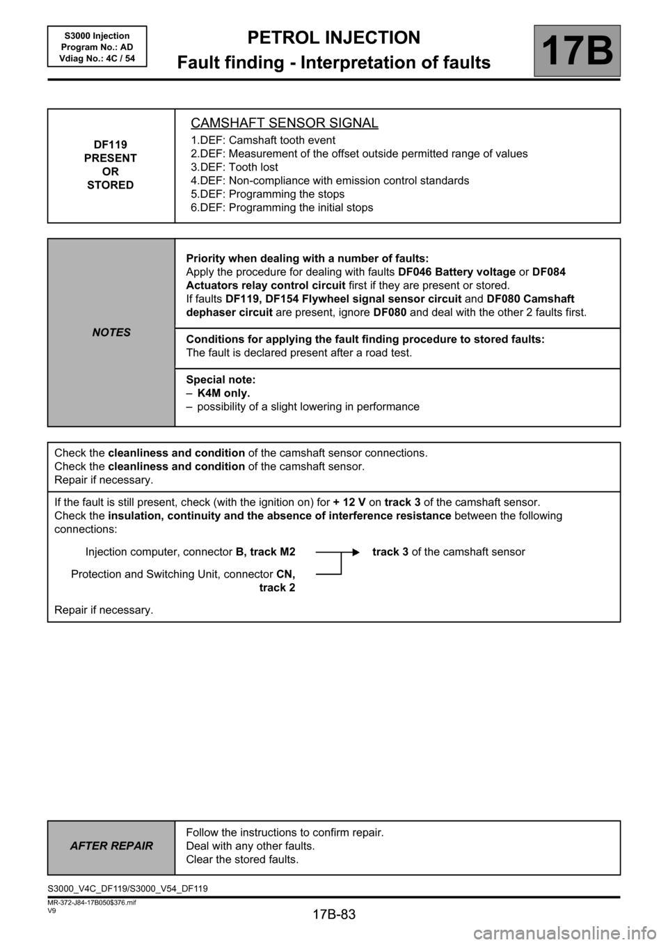
DF119
PRESENT
OR
STORED
CAMSHAFT SENSOR SIGNAL
1.DEF: Camshaft tooth event
2.DEF: Measurement of the offset outside permitted range of values
3.DEF: Tooth lost
4.DEF: Non-compliance with emission control standards
5.DEF: Programming the stops
6.DEF: Programming the initial stops
NOTESPriority when dealing with a number of faults:
Apply the procedure for dealing with faults DF046 Battery voltage or DF084
Actuators relay control circuit first if they are present or stored.
If faults DF119, DF154 Flywheel signal sensor circuit and DF080 Camshaft
dephaser circuit are present, ignore DF080 and deal with the other 2 faults first.
Conditions for applying the fault finding procedure to stored faults:
The fault is declared present after a road test.
Special note:
–K4M only.
– possibility of a slight lowering in performance
Check the cleanliness and condition of the camshaft sensor connections.
Check the cleanliness and condition of the camshaft sensor.
Repair if necessary.
If the fault is still present, check (with the ignition on) for + 12 V on track 3 of the camshaft sensor.
Check the insulation, continuity and the absence of interference resistance between the following
connections:
Injection computer, connectorB, track M2 track 3 of the camshaft sensor
Protection and Switching Unit, connectorCN,
track 2
Repair if necessary.
AFTER REPAIRFollow the instructions to confirm repair.
Deal with any other faults.
Clear the stored faults.
S3000_V4C_DF119/S3000_V54_DF119
Page 86 of 230
PETROL INJECTION
Fault finding - Interpretation of faults
17B
17B-86
PETROL INJECTION
Fault finding - Interpretation of faults
17B
17B-86V9 MR-372-J84-17B050$376.mif
S3000 Injection
Program No.: AD
Vdiag No.: 4C / 54
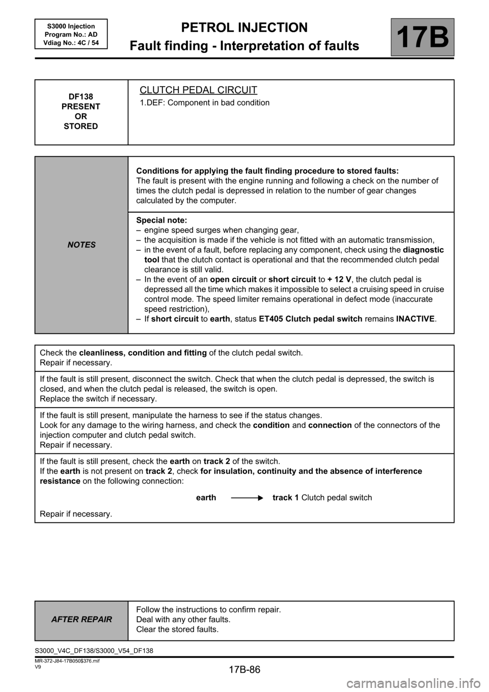
DF138
PRESENT
OR
STOREDCLUTCH PEDAL CIRCUIT
1.DEF: Component in bad condition
NOTESConditions for applying the fault finding procedure to stored faults:
The fault is present with the engine running and following a check on the number of
times the clutch pedal is depressed in relation to the number of gear changes
calculated by the computer.
Special note:
– engine speed surges when changing gear,
– the acquisition is made if the vehicle is not fitted with an automatic transmission,
– in the event of a fault, before replacing any component, check using the diagnostic
tool that the clutch contact is operational and that the recommended clutch pedal
clearance is still valid.
– In the event of an open circuit or short circuit to + 12 V, the clutch pedal is
depressed all the time which makes it impossible to select a cruising speed in cruise
control mode. The speed limiter remains operational in defect mode (inaccurate
speed restriction),
–If short circuit to earth, status ET405 Clutch pedal switch remains INACTIVE.
Check the cleanliness, condition and fitting of the clutch pedal switch.
Repair if necessary.
If the fault is still present, disconnect the switch. Check that when the clutch pedal is depressed, the switch is
closed, and when the clutch pedal is released, the switch is open.
Replace the switch if necessary.
If the fault is still present, manipulate the harness to see if the status changes.
Look for any damage to the wiring harness, and check the condition and connection of the connectors of the
injection computer and clutch pedal switch.
Repair if necessary.
If the fault is still present, check the earth on track 2 of the switch.
If the earth is not present on track 2, check for insulation, continuity and the absence of interference
resistance on the following connection:
earth track 1 Clutch pedal switch
Repair if necessary.
AFTER REPAIRFollow the instructions to confirm repair.
Deal with any other faults.
Clear the stored faults.
S3000_V4C_DF138/S3000_V54_DF138
Page 87 of 230
PETROL INJECTION
Fault finding - Interpretation of faults
17B
17B-87
PETROL INJECTION
Fault finding - Interpretation of faults
17B
17B-87V9 MR-372-J84-17B050$376.mif
S3000 Injection
Program No.: AD
Vdiag No.: 4C / 54
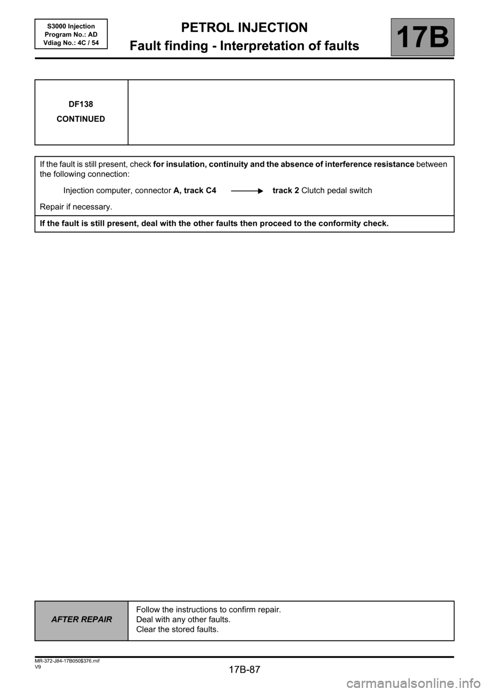
DF138
CONTINUED
If the fault is still present, check for insulation, continuity and the absence of interference resistance between
the following connection:
Injection computer, connectorA, track C4 track 2 Clutch pedal switch
Repair if necessary.
If the fault is still present, deal with the other faults then proceed to the conformity check.
AFTER REPAIRFollow the instructions to confirm repair.
Deal with any other faults.
Clear the stored faults.
Page 92 of 230
PETROL INJECTION
Fault finding - Interpretation of faults
17B
17B-92
PETROL INJECTION
Fault finding - Interpretation of faults
17B
17B-92V9 MR-372-J84-17B050$376.mif
S3000 Injection
Program No.: AD
Vdiag No.: 4C / 54
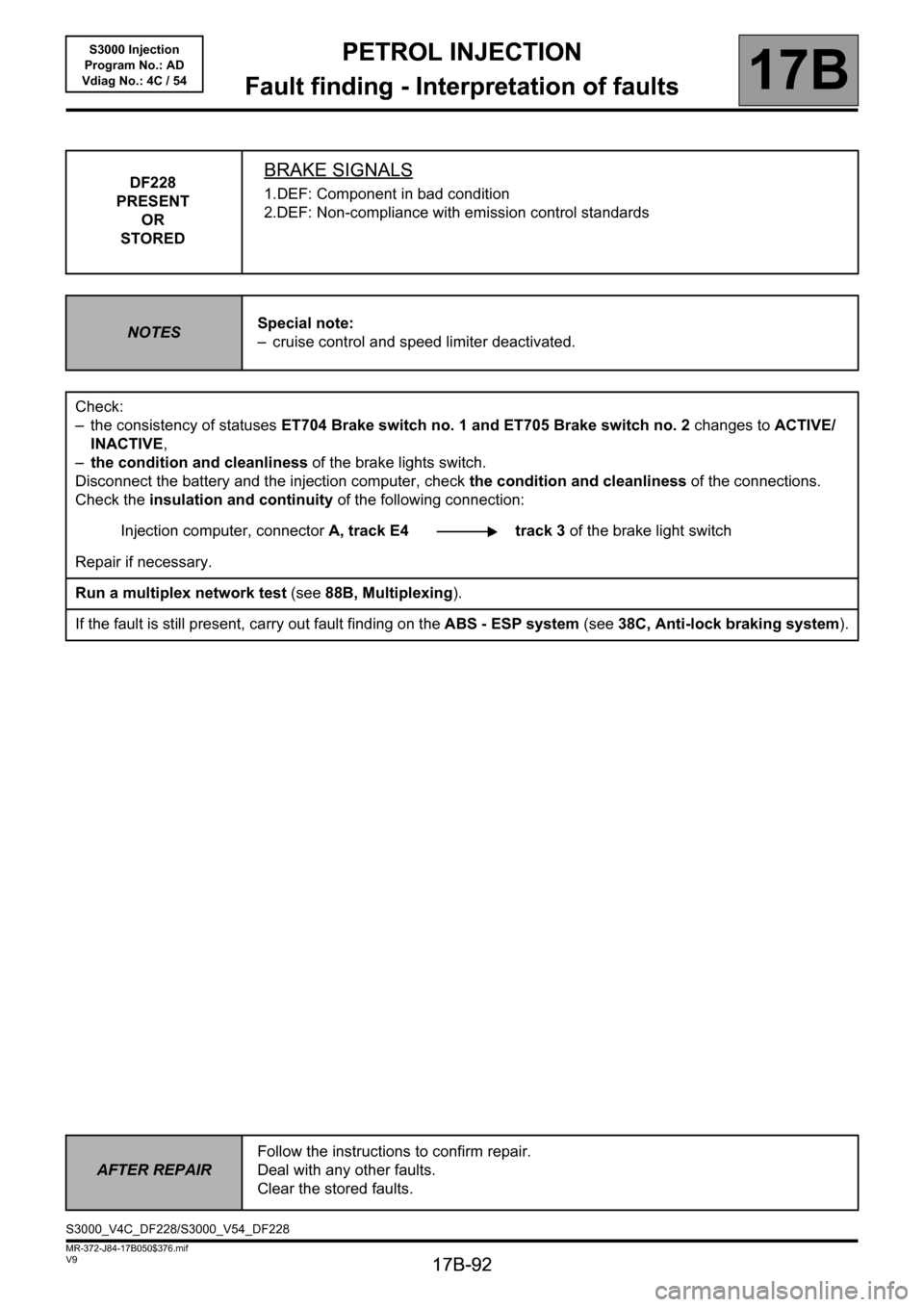
DF228
PRESENT
OR
STOREDBRAKE SIGNALS
1.DEF: Component in bad condition
2.DEF: Non-compliance with emission control standards
NOTESSpecial note:
– cruise control and speed limiter deactivated.
Check:
– the consistency of statuses ET704 Brake switch no. 1 and ET705 Brake switch no. 2 changes to ACTIVE/
INACTIVE,
–the condition and cleanliness of the brake lights switch.
Disconnect the battery and the injection computer, check the condition and cleanliness of the connections.
Check the insulation and continuity of the following connection:
Injection computer, connectorA, track E4 track 3 of the brake light switch
Repair if necessary.
Run a multiplex network test (see88B, Multiplexing).
If the fault is still present, carry out fault finding on the ABS - ESP system (see38C, Anti-lock braking system).
AFTER REPAIRFollow the instructions to confirm repair.
Deal with any other faults.
Clear the stored faults.
S3000_V4C_DF228/S3000_V54_DF228
Page 100 of 230
PETROL INJECTION
Fault finding - Interpretation of faults
17B
17B-100
PETROL INJECTION
Fault finding - Interpretation of faults
17B
17B-100V9 MR-372-J84-17B050$423.mif
S3000 Injection
Program No.: AD
Vdiag No.: 4C / 54
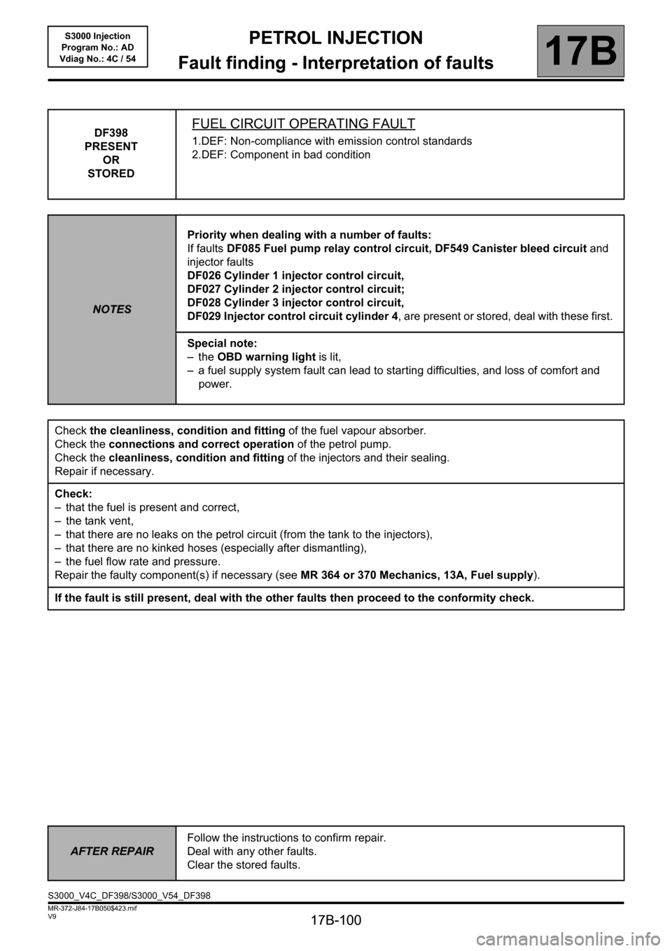
DF398
PRESENT
OR
STOREDFUEL CIRCUIT OPERATING FAULT
1.DEF: Non-compliance with emission control standards
2.DEF: Component in bad condition
NOTESPriority when dealing with a number of faults:
If faults DF085 Fuel pump relay control circuit, DF549 Canister bleed circuit and
injector faults
DF026 Cylinder 1 injector control circuit,
DF027 Cylinder 2 injector control circuit;
DF028 Cylinder 3 injector control circuit,
DF029 Injector control circuit cylinder 4, are present or stored, deal with these first.
Special note:
–the OBD warning light is lit,
– a fuel supply system fault can lead to starting difficulties, and loss of comfort and
power.
Check the cleanliness, condition and fitting of the fuel vapour absorber.
Check the connections and correct operation of the petrol pump.
Check the cleanliness, condition and fitting of the injectors and their sealing.
Repair if necessary.
Check:
– that the fuel is present and correct,
– the tank vent,
– that there are no leaks on the petrol circuit (from the tank to the injectors),
– that there are no kinked hoses (especially after dismantling),
– the fuel flow rate and pressure.
Repair the faulty component(s) if necessary (see MR 364 or 370 Mechanics, 13A, Fuel supply).
If the fault is still present, deal with the other faults then proceed to the conformity check.
AFTER REPAIRFollow the instructions to confirm repair.
Deal with any other faults.
Clear the stored faults.
S3000_V4C_DF398/S3000_V54_DF398