cruise control RENAULT SCENIC 2010 J95 / 3.G Petrol Injection S3000 Injection User Guide
[x] Cancel search | Manufacturer: RENAULT, Model Year: 2010, Model line: SCENIC, Model: RENAULT SCENIC 2010 J95 / 3.GPages: 230, PDF Size: 0.92 MB
Page 59 of 230
PETROL INJECTION
Fault finding - Interpretation of faults
17B
17B-59
PETROL INJECTION
Fault finding - Interpretation of faults
17B
17B-59V9 MR-372-J84-17B050$329.mif
S3000 Injection
Program No.: AD
Vdiag No.: 4C / 54
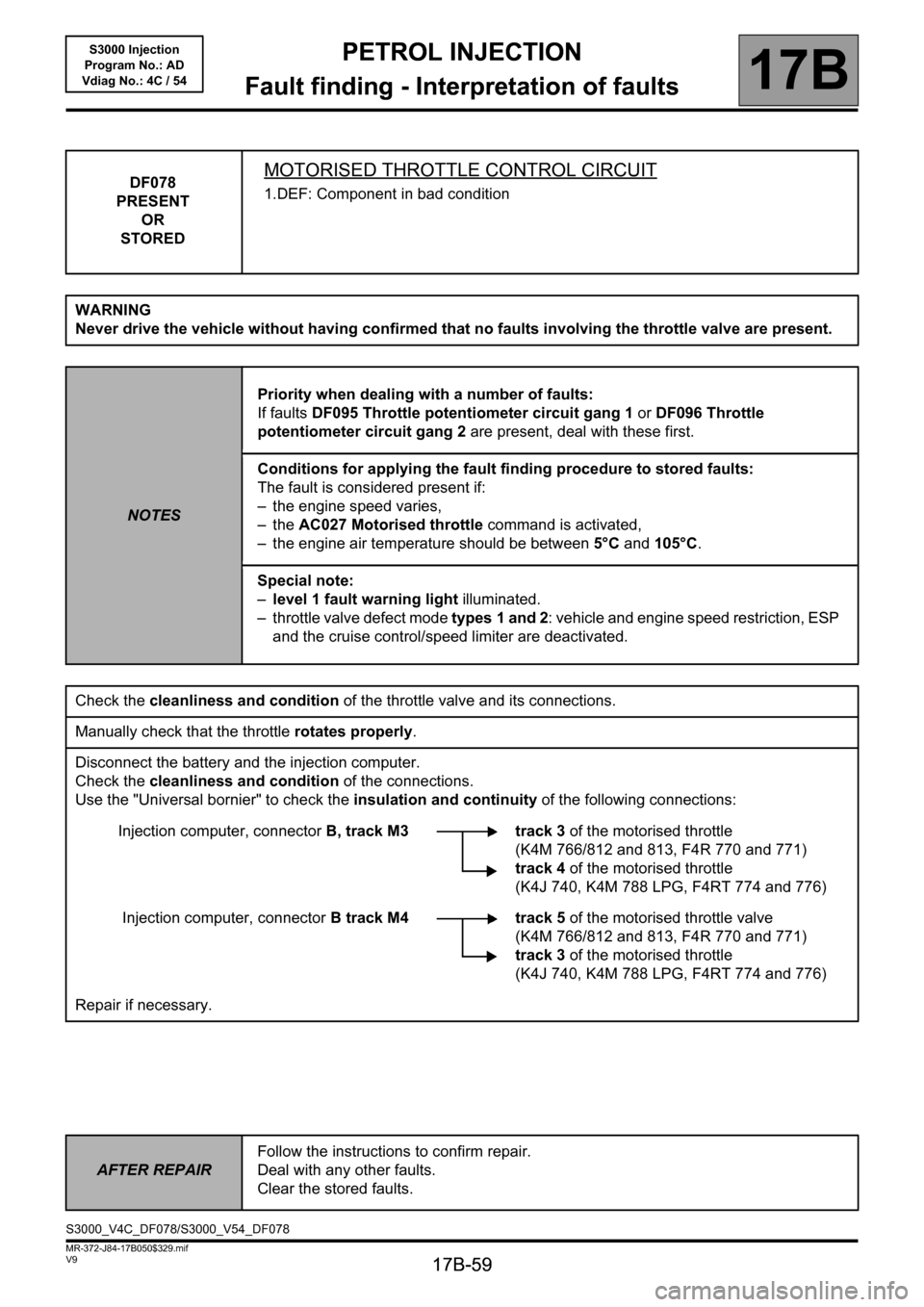
DF078
PRESENT
OR
STOREDMOTORISED THROTTLE CONTROL CIRCUIT
1.DEF: Component in bad condition
WARNING
Never drive the vehicle without having confirmed that no faults involving the throttle valve are present.
NOTESPriority when dealing with a number of faults:
If faults DF095 Throttle potentiometer circuit gang 1 or DF096 Throttle
potentiometer circuit gang 2 are present, deal with these first.
Conditions for applying the fault finding procedure to stored faults:
The fault is considered present if:
– the engine speed varies,
–the AC027 Motorised throttle command is activated,
– the engine air temperature should be between 5°C and 105°C.
Special note:
–level 1 fault warning light illuminated.
– throttle valve defect mode types 1 and 2: vehicle and engine speed restriction, ESP
and the cruise control/speed limiter are deactivated.
Check the cleanliness and condition of the throttle valve and its connections.
Manually check that the throttle rotates properly.
Disconnect the battery and the injection computer.
Check the cleanliness and condition of the connections.
Use the "Universal bornier" to check the insulation and continuity of the following connections:
Injection computer, connectorB, track M3 track 3 of the motorised throttle
(K4M 766/812 and 813, F4R 770 and 771)
track 4of the motorised throttle
(K4J 740, K4M 788 LPG, F4RT 774 and 776)
Injection computer, connectorB track M4 track 5 of the motorised throttle valve
(K4M 766/812 and 813, F4R 770 and 771)
track 3 of the motorised throttle
(K4J 740, K4M 788 LPG, F4RT 774 and 776)
Repair if necessary.
AFTER REPAIRFollow the instructions to confirm repair.
Deal with any other faults.
Clear the stored faults.
S3000_V4C_DF078/S3000_V54_DF078
Page 61 of 230
PETROL INJECTION
Fault finding - Interpretation of faults
17B
17B-61
PETROL INJECTION
Fault finding - Interpretation of faults
17B
17B-61V9 MR-372-J84-17B050$329.mif
S3000 Injection
Program No.: AD
Vdiag No.: 4C / 54
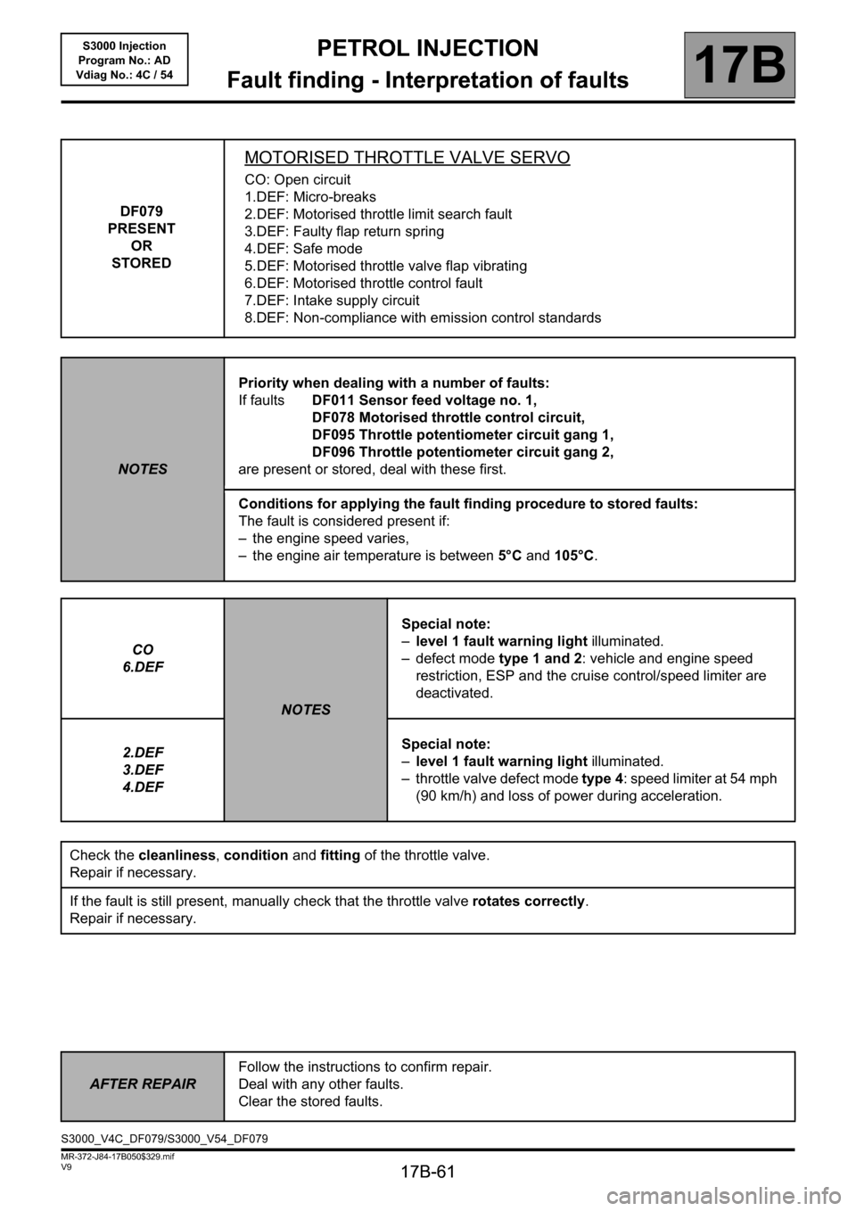
DF079
PRESENT
OR
STORED
MOTORISED THROTTLE VALVE SERVO
CO: Open circuit
1.DEF: Micro-breaks
2.DEF: Motorised throttle limit search fault
3.DEF: Faulty flap return spring
4.DEF: Safe mode
5.DEF: Motorised throttle valve flap vibrating
6.DEF: Motorised throttle control fault
7.DEF: Intake supply circuit
8.DEF: Non-compliance with emission control standards
NOTESPriority when dealing with a number of faults:
If faultsDF011 Sensor feed voltage no. 1,
DF078 Motorised throttle control circuit,
DF095 Throttle potentiometer circuit gang 1,
DF096 Throttle potentiometer circuit gang 2,
are present or stored, deal with these first.
Conditions for applying the fault finding procedure to stored faults:
The fault is considered present if:
– the engine speed varies,
– the engine air temperature is between 5°C and 105°C.
CO
6.DEF
NOTESSpecial note:
–level 1 fault warning light illuminated.
– defect mode type 1 and 2: vehicle and engine speed
restriction, ESP and the cruise control/speed limiter are
deactivated.
2.DEF
3.DEF
4.DEFSpecial note:
–level 1 fault warning light illuminated.
– throttle valve defect mode type 4: speed limiter at 54 mph
(90 km/h) and loss of power during acceleration.
Check the cleanliness, condition and fitting of the throttle valve.
Repair if necessary.
If the fault is still present, manually check that the throttle valve rotates correctly.
Repair if necessary.
AFTER REPAIRFollow the instructions to confirm repair.
Deal with any other faults.
Clear the stored faults.
S3000_V4C_DF079/S3000_V54_DF079
Page 71 of 230
PETROL INJECTION
Fault finding - Interpretation of faults
17B
17B-71
PETROL INJECTION
Fault finding - Interpretation of faults
17B
17B-71V9 MR-372-J84-17B050$376.mif
S3000 Injection
Program No.: AD
Vdiag No.: 4C / 54
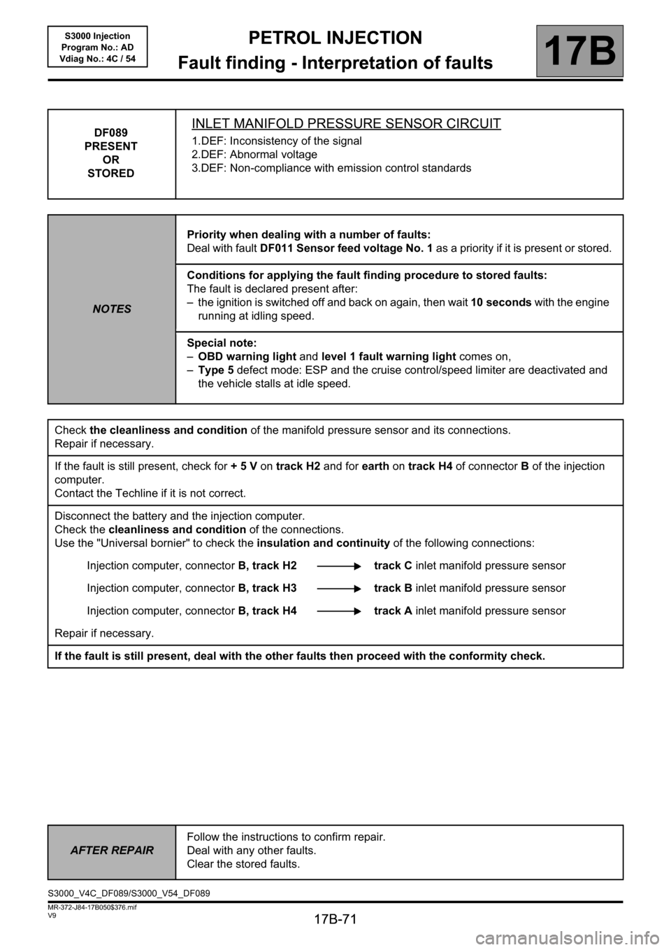
DF089
PRESENT
OR
STOREDINLET MANIFOLD PRESSURE SENSOR CIRCUIT
1.DEF: Inconsistency of the signal
2.DEF: Abnormal voltage
3.DEF: Non-compliance with emission control standards
NOTESPriority when dealing with a number of faults:
Deal with fault DF011 Sensor feed voltage No. 1 as a priority if it is present or stored.
Conditions for applying the fault finding procedure to stored faults:
The fault is declared present after:
– the ignition is switched off and back on again, then wait 10 seconds with the engine
running at idling speed.
Special note:
–OBD warning light and level 1 fault warning light comes on,
–Type 5 defect mode: ESP and the cruise control/speed limiter are deactivated and
the vehicle stalls at idle speed.
Check the cleanliness and condition of the manifold pressure sensor and its connections.
Repair if necessary.
If the fault is still present, check for + 5 V on track H2 and for earth on track H4 of connectorB of the injection
computer.
Contact the Techline if it is not correct.
Disconnect the battery and the injection computer.
Check the cleanliness and condition of the connections.
Use the "Universal bornier" to check the insulation and continuity of the following connections:
Injection computer, connectorB, track H2 track C inlet manifold pressure sensor
Injection computer, connectorB, track H3 track B inlet manifold pressure sensor
Injection computer, connectorB, track H4 track A inlet manifold pressure sensor
Repair if necessary.
If the fault is still present, deal with the other faults then proceed with the conformity check.
AFTER REPAIRFollow the instructions to confirm repair.
Deal with any other faults.
Clear the stored faults.
S3000_V4C_DF089/S3000_V54_DF089
Page 80 of 230
PETROL INJECTION
Fault finding - Interpretation of faults
17B
17B-80
PETROL INJECTION
Fault finding - Interpretation of faults
17B
17B-80V9 MR-372-J84-17B050$376.mif
S3000 Injection
Program No.: AD
Vdiag No.: 4C / 54
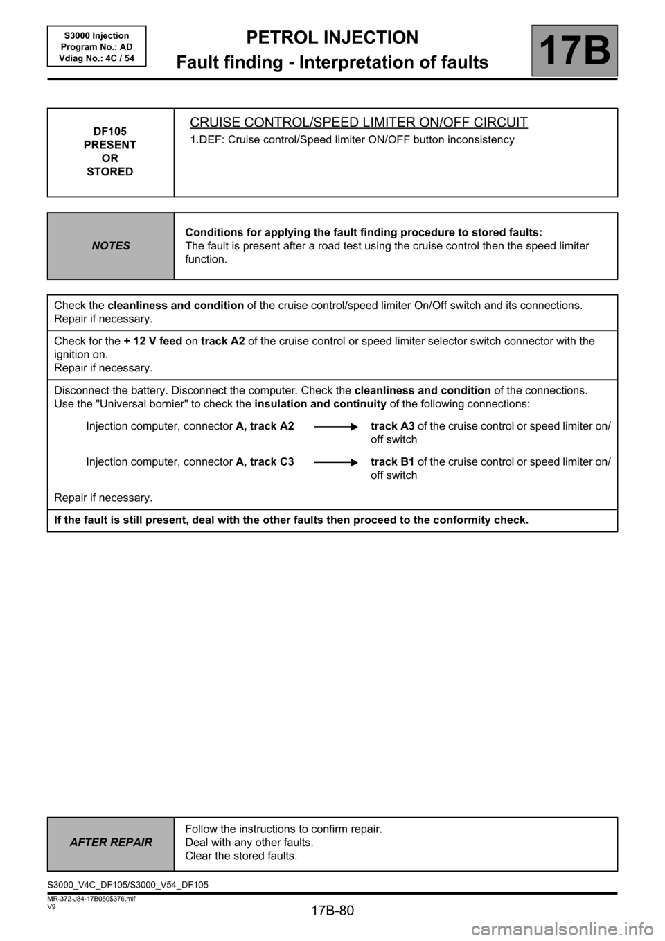
DF105
PRESENT
OR
STOREDCRUISE CONTROL/SPEED LIMITER ON/OFF CIRCUIT
1.DEF: Cruise control/Speed limiter ON/OFF button inconsistency
NOTESConditions for applying the fault finding procedure to stored faults:
The fault is present after a road test using the cruise control then the speed limiter
function.
Check the cleanliness and condition of the cruise control/speed limiter On/Off switch and its connections.
Repair if necessary.
Check for the + 12 V feed on track A2 of the cruise control or speed limiter selector switch connector with the
ignition on.
Repair if necessary.
Disconnect the battery. Disconnect the computer. Check the cleanliness and condition of the connections.
Use the "Universal bornier" to check the insulation and continuity of the following connections:
Injection computer, connectorA, track A2 track A3 of the cruise control or speed limiter on/
off switch
Injection computer, connectorA, track C3 track B1 of the cruise control or speed limiter on/
off switch
Repair if necessary.
If the fault is still present, deal with the other faults then proceed to the conformity check.
AFTER REPAIRFollow the instructions to confirm repair.
Deal with any other faults.
Clear the stored faults.
S3000_V4C_DF105/S3000_V54_DF105
Page 81 of 230
PETROL INJECTION
Fault finding - Interpretation of faults
17B
17B-81
PETROL INJECTION
Fault finding - Interpretation of faults
17B
17B-81V9 MR-372-J84-17B050$376.mif
S3000 Injection
Program No.: AD
Vdiag No.: 4C / 54
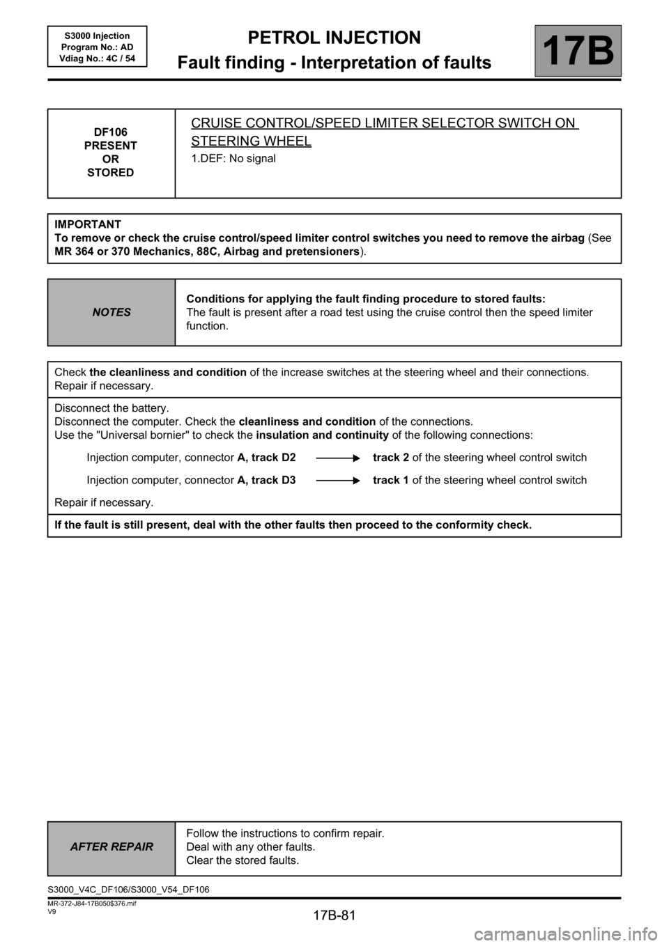
DF106
PRESENT
OR
STOREDCRUISE CONTROL/SPEED LIMITER SELECTOR SWITCH ON
STEERING WHEEL
1.DEF: No signal
IMPORTANT
To remove or check the cruise control/speed limiter control switches you need to remove the airbag (See
MR 364 or 370 Mechanics, 88C, Airbag and pretensioners).
NOTESConditions for applying the fault finding procedure to stored faults:
The fault is present after a road test using the cruise control then the speed limiter
function.
Check the cleanliness and condition of the increase switches at the steering wheel and their connections.
Repair if necessary.
Disconnect the battery.
Disconnect the computer. Check the cleanliness and condition of the connections.
Use the "Universal bornier" to check the insulation and continuity of the following connections:
Injection computer, connectorA, track D2 track 2 of the steering wheel control switch
Injection computer, connectorA, track D3 track 1 of the steering wheel control switch
Repair if necessary.
If the fault is still present, deal with the other faults then proceed to the conformity check.
AFTER REPAIRFollow the instructions to confirm repair.
Deal with any other faults.
Clear the stored faults.
S3000_V4C_DF106/S3000_V54_DF106
Page 86 of 230
PETROL INJECTION
Fault finding - Interpretation of faults
17B
17B-86
PETROL INJECTION
Fault finding - Interpretation of faults
17B
17B-86V9 MR-372-J84-17B050$376.mif
S3000 Injection
Program No.: AD
Vdiag No.: 4C / 54
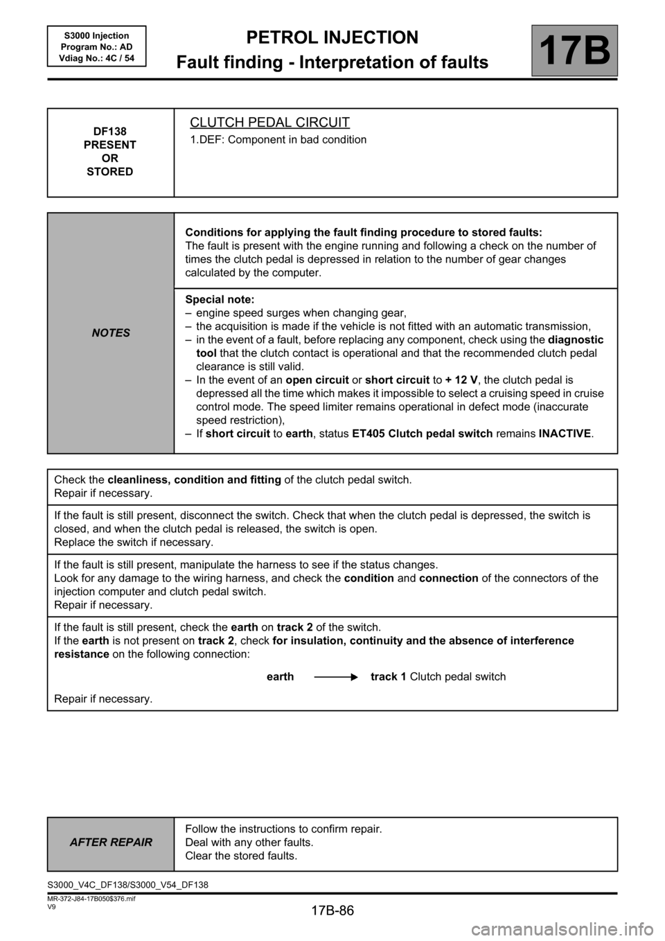
DF138
PRESENT
OR
STOREDCLUTCH PEDAL CIRCUIT
1.DEF: Component in bad condition
NOTESConditions for applying the fault finding procedure to stored faults:
The fault is present with the engine running and following a check on the number of
times the clutch pedal is depressed in relation to the number of gear changes
calculated by the computer.
Special note:
– engine speed surges when changing gear,
– the acquisition is made if the vehicle is not fitted with an automatic transmission,
– in the event of a fault, before replacing any component, check using the diagnostic
tool that the clutch contact is operational and that the recommended clutch pedal
clearance is still valid.
– In the event of an open circuit or short circuit to + 12 V, the clutch pedal is
depressed all the time which makes it impossible to select a cruising speed in cruise
control mode. The speed limiter remains operational in defect mode (inaccurate
speed restriction),
–If short circuit to earth, status ET405 Clutch pedal switch remains INACTIVE.
Check the cleanliness, condition and fitting of the clutch pedal switch.
Repair if necessary.
If the fault is still present, disconnect the switch. Check that when the clutch pedal is depressed, the switch is
closed, and when the clutch pedal is released, the switch is open.
Replace the switch if necessary.
If the fault is still present, manipulate the harness to see if the status changes.
Look for any damage to the wiring harness, and check the condition and connection of the connectors of the
injection computer and clutch pedal switch.
Repair if necessary.
If the fault is still present, check the earth on track 2 of the switch.
If the earth is not present on track 2, check for insulation, continuity and the absence of interference
resistance on the following connection:
earth track 1 Clutch pedal switch
Repair if necessary.
AFTER REPAIRFollow the instructions to confirm repair.
Deal with any other faults.
Clear the stored faults.
S3000_V4C_DF138/S3000_V54_DF138
Page 92 of 230
PETROL INJECTION
Fault finding - Interpretation of faults
17B
17B-92
PETROL INJECTION
Fault finding - Interpretation of faults
17B
17B-92V9 MR-372-J84-17B050$376.mif
S3000 Injection
Program No.: AD
Vdiag No.: 4C / 54
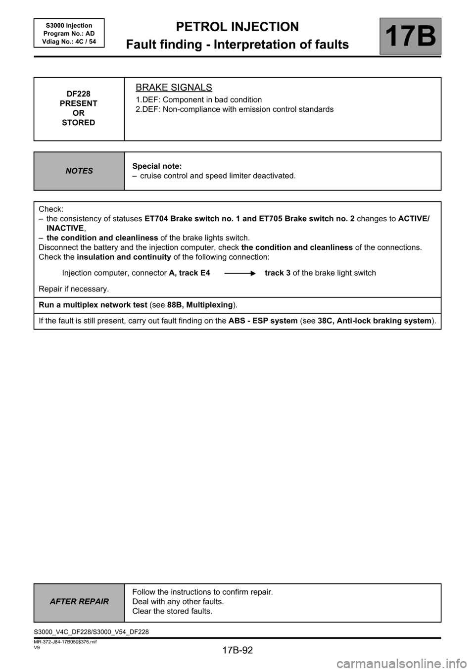
DF228
PRESENT
OR
STOREDBRAKE SIGNALS
1.DEF: Component in bad condition
2.DEF: Non-compliance with emission control standards
NOTESSpecial note:
– cruise control and speed limiter deactivated.
Check:
– the consistency of statuses ET704 Brake switch no. 1 and ET705 Brake switch no. 2 changes to ACTIVE/
INACTIVE,
–the condition and cleanliness of the brake lights switch.
Disconnect the battery and the injection computer, check the condition and cleanliness of the connections.
Check the insulation and continuity of the following connection:
Injection computer, connectorA, track E4 track 3 of the brake light switch
Repair if necessary.
Run a multiplex network test (see88B, Multiplexing).
If the fault is still present, carry out fault finding on the ABS - ESP system (see38C, Anti-lock braking system).
AFTER REPAIRFollow the instructions to confirm repair.
Deal with any other faults.
Clear the stored faults.
S3000_V4C_DF228/S3000_V54_DF228
Page 102 of 230
PETROL INJECTION
Fault finding - Interpretation of faults
17B
17B-102
PETROL INJECTION
Fault finding - Interpretation of faults
17B
17B-102V9 MR-372-J84-17B050$423.mif
S3000 Injection
Program No.: AD
Vdiag No.: 4C / 54
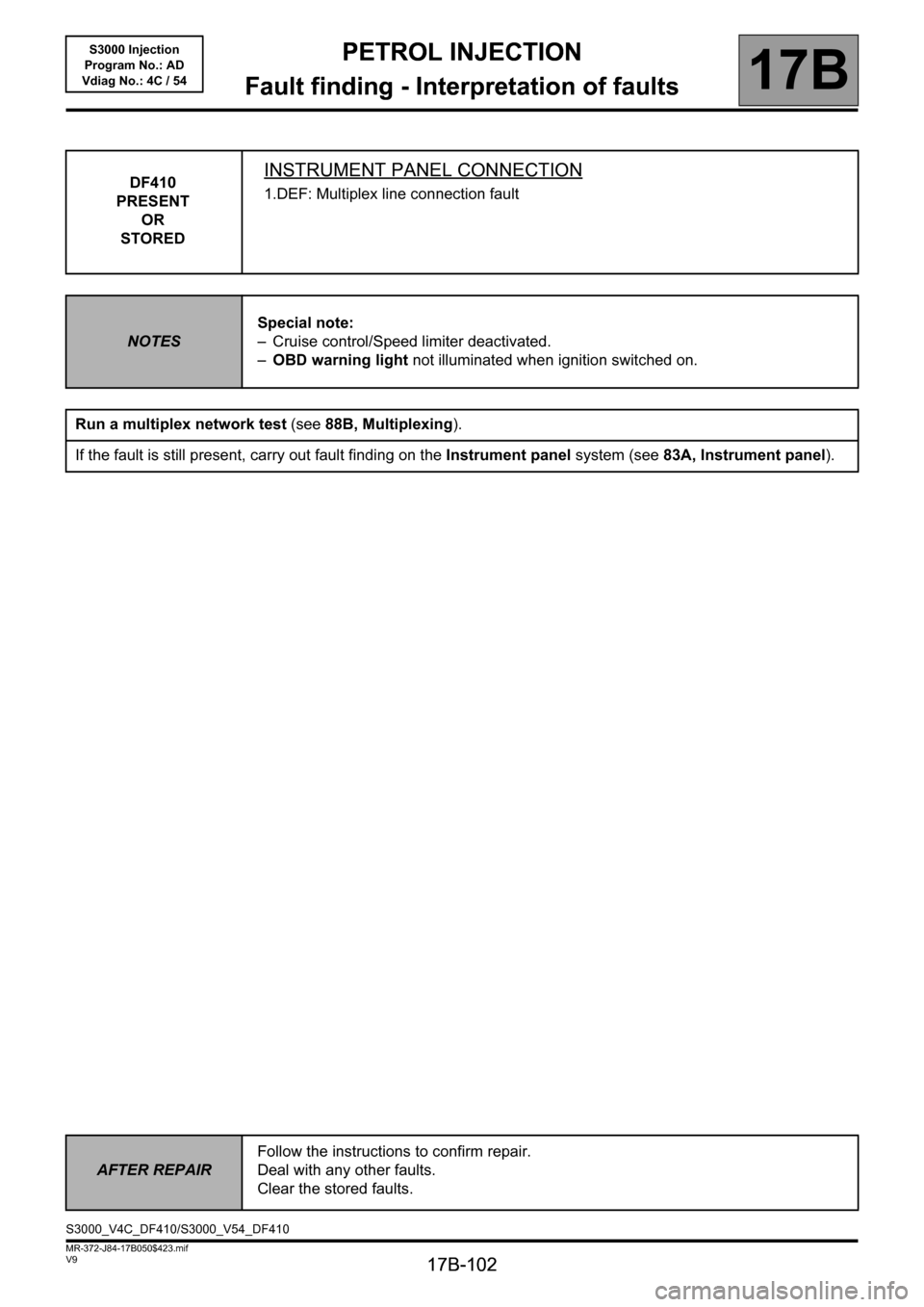
DF410
PRESENT
OR
STOREDINSTRUMENT PANEL CONNECTION
1.DEF: Multiplex line connection fault
NOTESSpecial note:
– Cruise control/Speed limiter deactivated.
–OBD warning light not illuminated when ignition switched on.
Run a multiplex network test (see88B, Multiplexing).
If the fault is still present, carry out fault finding on the Instrument panel system (see83A, Instrument panel).
AFTER REPAIRFollow the instructions to confirm repair.
Deal with any other faults.
Clear the stored faults.
S3000_V4C_DF410/S3000_V54_DF410
Page 110 of 230
PETROL INJECTION
Fault finding - Interpretation of faults
17B
17B-110
PETROL INJECTION
Fault finding - Interpretation of faults
17B
17B-110V9 MR-372-J84-17B050$423.mif
S3000 Injection
Program No.: AD
Vdiag No.: 4C / 54
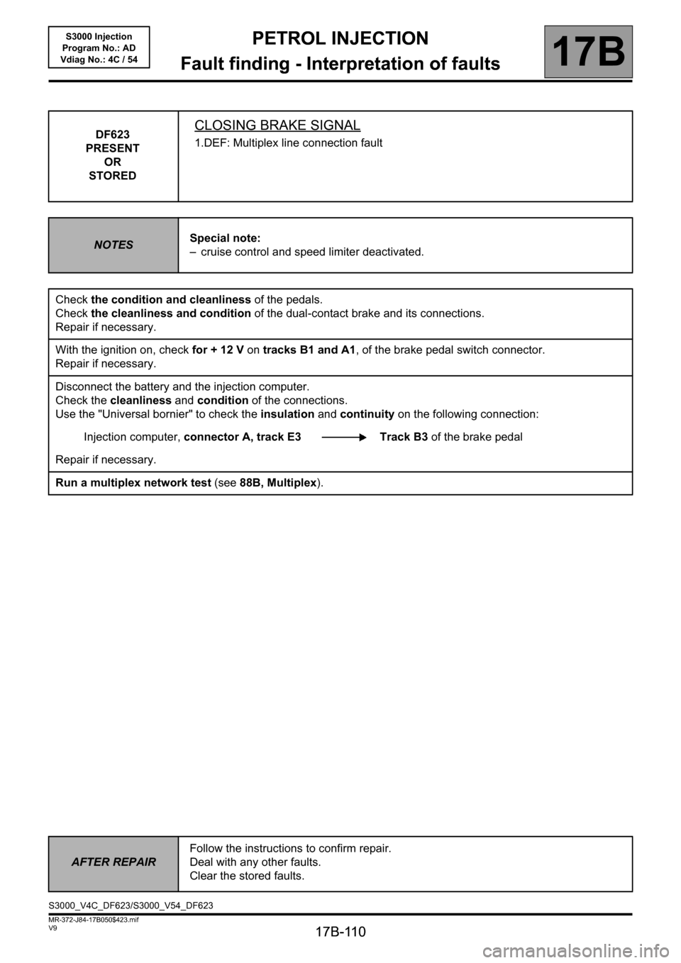
DF623
PRESENT
OR
STOREDCLOSING BRAKE SIGNAL
1.DEF: Multiplex line connection fault
NOTESSpecial note:
– cruise control and speed limiter deactivated.
Check the condition and cleanliness of the pedals.
Check the cleanliness and condition of the dual-contact brake and its connections.
Repair if necessary.
With the ignition on, check for + 12 V on tracks B1 and A1, of the brake pedal switch connector.
Repair if necessary.
Disconnect the battery and the injection computer.
Check the cleanliness and condition of the connections.
Use the "Universal bornier" to check the insulation and continuity on the following connection:
Injection computer, connector A, track E3 Track B3 of the brake pedal
Repair if necessary.
Run a multiplex network test (see88B, Multiplex).
AFTER REPAIRFollow the instructions to confirm repair.
Deal with any other faults.
Clear the stored faults.
S3000_V4C_DF623/S3000_V54_DF623
Page 117 of 230
PETROL INJECTION
Fault finding - Interpretation of faults
17B
17B-117
PETROL INJECTION
Fault finding - Interpretation of faults
17B
17B-117V9 MR-372-J84-17B050$423.mif
S3000 Injection
Program No.: AD
Vdiag No.: 4C / 54
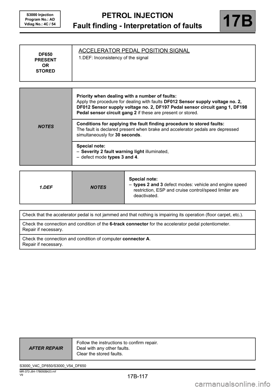
DF650
PRESENT
OR
STOREDACCELERATOR PEDAL POSITION SIGNAL
1.DEF: Inconsistency of the signal
NOTESPriority when dealing with a number of faults:
Apply the procedure for dealing with faults DF012 Sensor supply voltage no. 2,
DF012 Sensor supply voltage no. 2, DF197 Pedal sensor circuit gang 1, DF198
Pedal sensor circuit gang 2 if these are present or stored.
Conditions for applying the fault finding procedure to stored faults:
The fault is declared present when brake and accelerator pedals are depressed
simultaneously for 30 seconds.
Special note:
–Severity 2 fault warning light illuminated,
– defect mode types 3 and 4.
1.DEF
NOTESSpecial note:
–types 2 and 3 defect modes: vehicle and engine speed
restriction, ESP and cruise control/speed limiter are
deactivated.
Check that the accelerator pedal is not jammed and that nothing is impairing its operation (floor carpet, etc.).
Check the connection and condition of the 6-track connector for the accelerator pedal potentiometer.
Repair if necessary.
Check the connection and condition of computer connector A.
Repair if necessary.
AFTER REPAIRFollow the instructions to confirm repair.
Deal with any other faults.
Clear the stored faults.
S3000_V4C_DF650/S3000_V54_DF650