cruise control RENAULT SCENIC 2010 J95 / 3.G Petrol Injection S3000 Injection Workshop Manual
[x] Cancel search | Manufacturer: RENAULT, Model Year: 2010, Model line: SCENIC, Model: RENAULT SCENIC 2010 J95 / 3.GPages: 230, PDF Size: 0.92 MB
Page 7 of 230

PETROL INJECTION
Fault finding - System operation
17B
17B - 7
PETROL INJECTION
Fault finding - System operation
17B
17B - 7V9 MR-372-J84-17B050$094.mif
S3000 Injection
Program No.: AD
Vdiag No.: 4C / 54PETROL INJECTION
Fault finding - System operation
1. SYSTEM OPERATION
Composition
The injection system consists of the:
– accelerator potentiometer,
– clutch pedal switch,
– TDC sensor,
– atmospheric pressure sensor,
– air temperature sensor,
– coolant temperature sensor,
– upstream oxygen sensor,
– downstream oxygen sensor,
– cruise control switch,
– steering column switch,
– cruise control on/off switch,
– fuel vapour absorber,
– injection computer,
– motorised throttle valve,
– 4 injectors,
– 4 pencil coils,
– pinking sensor,
– camshaft dephaser solenoid valve (non-LPG K4M only),
– camshaft position sensor (non-LPG K4M only),
– turbocharging pressure sensor (F4R turbo only)
– electric coolant pump (F4R turbo only),
– wastegate solenoid valve (only on F4R Turbo),
– turbocharging solenoid valve (only on F4R-Turbo)
Computer
128 track SAGEM type S3000 FLASH EEPROM computer controlling injection and ignition.
Multipoint injection in sequential mode.
Connections to the other computers:
– air conditioning,
– UCH,
– protection and switching unit (UPC)
– Automatic Gearbox Electronic Control Unit (AUTO).
– airbag,
– ABS/ESP,
– instrument panel.
MR-372-J84-17B050$094.mif
Page 8 of 230

PETROL INJECTION
Fault finding - System operation
17B
17B - 8
PETROL INJECTION
Fault finding - System operation
17B
17B - 8V9 MR-372-J84-17B050$094.mif
S3000 Injection
Program No.: AD
Vdiag No.: 4C / 54
2. Role of components, operating strategy
Engine immobiliser
The Verlog 4 type immobiliser function is managed by the UCH computer and the engine management computer.
Before any starting request, the engine management computer is protected.
When a starting request is made, the injection computer and the UCH exchange authentication data via the multiplex
network; this determines whether the engine start is authorised.
After more than 5 consecutive failed authentication attempts, the engine management computer goes into protection
(antiscanning) mode and no longer tries to authenticate the UCH computer. It only exits this mode when the
following sequence of operations occurs:
– the ignition is left on for at least 20 seconds,
– the message is switched off,
– the injection computer self-supply cuts out when it should (the time varies according to engine temperature).
After this, only one authentication attempt is allowed. If this fails again, repeat the sequence of operations described
above.
If the engine management computer still fails to unlock, contact the Techline.
Impact detected
If an impact has been stored by the injection computer, switch off the ignition for 10 seconds, then switch it back on
so that the engine can be started. Clear the faults.
Torque management
The torque structure is the system for managing engine torque. It is necessary for some functions such as the
electronic stability program (ESP) and the automatic gearbox.
Each inter-system (ESP and automatic gearbox) sends a request for torque via the multiplex network to the injection
computer. It arbitrates between the inter-system torque requests and the driver's request (pedal or cruise control/
speed limiter). The result of the arbitration gives the torque setpoint. The torque structure uses the torque setpoint to
calculate the throttle position setpoint, the advance and, if there is turbocharging, the turbocharger valve setpoint
(wastegate) for engines fitted with a turbocharger. WARNING
Disconnect the injection computer when carrying out any welding work on the vehicle.
Page 17 of 230

PETROL INJECTION
Fault finding - System operation
17B
17B - 17
PETROL INJECTION
Fault finding - System operation
17B
17B - 17V9 MR-372-J84-17B050$094.mif
S3000 Injection
Program No.: AD
Vdiag No.: 4C / 54
6. Defect modes
Motorised throttle valve
In defect mode, the motorised throttle valve can have 6 different statuses.
Any entry into type 1 to 5 defect mode always leads to the application of type 6. Type 1The throttle opening is less than the Safe mode position. The throttle is no longer activated and is
automatically in Safe mode. The ESP, distance control and cruise control/speed limiter systems are
disabled. The automatic transmission is in "Safe mode".
Type 2The throttle opening is no longer actuated. The engine speed is limited by injection cut-off.
Type 3Defect mode is associated with restructuring of the pedal setpoints (constant pedal setpoint for each
gear).
Type 4The associated defect mode restricts the throttle opening. The maximum throttle valve opening
threshold results in a speed of below 54 mph (90 km/h).
Type 5The computer no longer processes torque changes requested by the ESP, distance control, cruise
control/speed limiter and automatic gearbox systems. This defect mode results from a computer
malfunction, or a fault with the manifold or turbocharging pressure sensor. The system then only uses
the accelerator pedal signal. The ESP, distance control and cruise control/speed limiter systems are
disabled. The automatic transmission is in "Safe mode".
Type 6The turbocharging valve no longer works.
Page 21 of 230

PETROL INJECTION
17B
17B - 21
17B
17B - 21V9 MR-372-J84-17B050$141.mif
S3000 Injection
Program No.: AD
Vdiag No.: 4C / 54PETROL INJECTION
Fault finding - Allocation of computer tracks
Connector (A), 32 tracks:
Track Description
A1 Not used
A2 Cruise control on/off button logical input
A3 CAN L1 passenger compartment multiplex connection
A4 CAN H1 passenger compartment multiplex connection
B1 Not used
B2 Not used
B3 Not used
B4 OBD diagnostic line K
C1 Not used
C2 Not used
C3 Speed limiter on/off button logical input
C4 + Clutch switch signal
D1 + after ignition feed via UPC
D2 Cruise control signal analogue input
D3 Cruise control signal earth
D4 Not used
E1 Not used
E2 Not used
E3 Not used
E4 Brake pedal normally closed switch no. 1 signal
F1 Not used
F2 + 5 V supply, accelerator pedal potentiometer gang 2
F3 Accelerator pedal potentiometer signal, gang 2
F4 Accelerator pedal potentiometer earth, gang 2
G1 Not used
G2 + 5 V supply, accelerator pedal potentiometer gang 1
G3 Not used
G4 Not used
H1 Not used
H2 Accelerator pedal potentiometer signal, gang 1
H3 Accelerator pedal potentiometer earth, gang 1
H4 Not used
MR-372-J84-17B050$141.mif
Page 26 of 230

PETROL INJECTION
Fault finding - Replacement of components
17B
17B-26
PETROL INJECTION
Fault finding - Replacement of components
17B
17B-26V9 MR-372-J84-17B050$188.mif
S3000 Injection
Program No.: AD
Vdiag No.: 4C / 54PETROL INJECTION
Fault finding - Replacement of components
1. COMPUTER REPLACEMENT OR REPROGRAMMING OPERATIONS
The system can be programmed and reprogrammed via the diagnostic socket using the RENAULT CLIP diagnostic
tool (Consult Technical Note 3585A or follow the instructions provided by the diagnostic tool).
Whenever the computer has been programmed, reprogrammed or replaced:
–Switch off the ignition.
–Start and then stop the engine (to initialise the computer) and wait 30 seconds.
–Switch the ignition back on and use the diagnostic tool to carry out the following steps:
– use command VP020 Enter VIN.
– deal with any faults declared by the diagnostic tool. Clear the computer memory.
– program the flywheel sensor target and throttle stops,
– carry out a road test followed by another check with the diagnostic tool. IMPORTANT
–Switch on the diagnostic tool (mains or cigarette lighter supply).
–Connect a battery charger (during the entire computer (re)programming procedure, the engine fan
assemblies are triggered automatically).
–Observe the engine temperature setpoints given on the diagnostic tool before (re)programming.
–Cut off all the electrical consumers (interior lighting, air conditioning, radio, etc.).
Operations to be carried out before the injection computer is reprogrammed:
Before reprogramming the injection computer, move the main Cruise control/Speed limiter switch to the rest
position. The information about the cruise control or the speed limiter displayed on the instrument panel
disappears.
Otherwise, if the main switch remains in the cruise control or speed limiter position during and after reprogramming,
the Cruise control/Speed limiter function will not be operational.
The procedure for resetting the function is as follows:
Vehicle ignition on.
– Position the main switch in rest position (the computer then detects the rest position).
– Position the switch in Cruise control position to activate the Cruise control function.
– Position the switch in Speed limiter position to activate the Speed limiter function.
IMPORTANT
It is not possible to try an injection computer coming from the Parts Department because it will no longer be
possible to use it on another vehicle.
MR-372-J84-17B050$188.mif
Page 32 of 230

PETROL INJECTION
Fault finding - Fault summary table
17B
17B-32
PETROL INJECTION
Fault finding - Fault summary table
17B
17B-32V9 MR-372-J84-17B050$282.mif
S3000 Injection
Program No.: AD
Vdiag No.: 4C / 54
Tool faultAssociated
DTC codeDescriptionLevel 2 fault
warning light
(Red brake
warning light)Level 1 fault
warning light
(Orange
injection
warning light)No warning
light onOBD
warning light
DF102 2502Signal: power sig.*
available1.DEF
DF105 0585Cruise control/
speed limiter on/off
circuit1.DEF
DF106 0575Cruise control/
speed limiter
function selectors
on steering wheel1.DEF
DF109 0313Low fuel level
misfiring1.DEF/
2.DEF/
3.DEF
DF119 0340Camshaft sensor
signal1.DEF/2.DEF/
3.DEF/4.DEF
DF126 1604Passenger
compartment
heating resistor
(RCH)1.DEF
DF138 0830 Clutch pedal switch 1.DEF
DF154 0335Flywheel signal
sensor circuit1.DEF/2.DEF/
3.DEF
DF196 0225Pedal sensor
circuit gang 11.DEF
CO/CC.0/
CC.1CO/CC.0/
CC.1
2.DEF
DF198 2120Pedal sensor
circuit gang 2CO
CC.0/ CC.1CO
CC.0/ CC.1
DF228 0504 Brake signal 1.DEF/2.DEF
DF232 0530Refrigerant
pressure sensor
circuit1.DEF
DF361 0351Ignition coil control
- cylinders 1 - 4CO.0/CC.1
1.DEFCO.0/CC.1
1.DEF
DF362 0352Ignition coil control
- cylinders 2 - 3CO.0/CC.1
1.DEFCO.0/CC.1
1.DEF
DF377 C115Petrol↔ LPG
connection1.DEF/2.DEF
DF394 0420Catalytic converter
operating fault1.DEF/
2.DEF
DF398 0170Fuel circuit
operating faultCO/ 1.DEF
Page 37 of 230

PETROL INJECTION
Fault finding - Interpretation of faults
17B
17B-37
PETROL INJECTION
Fault finding - Interpretation of faults
17B
17B-37V9 MR-372-J84-17B050$329.mif
S3000 Injection
Program No.: AD
Vdiag No.: 4C / 54
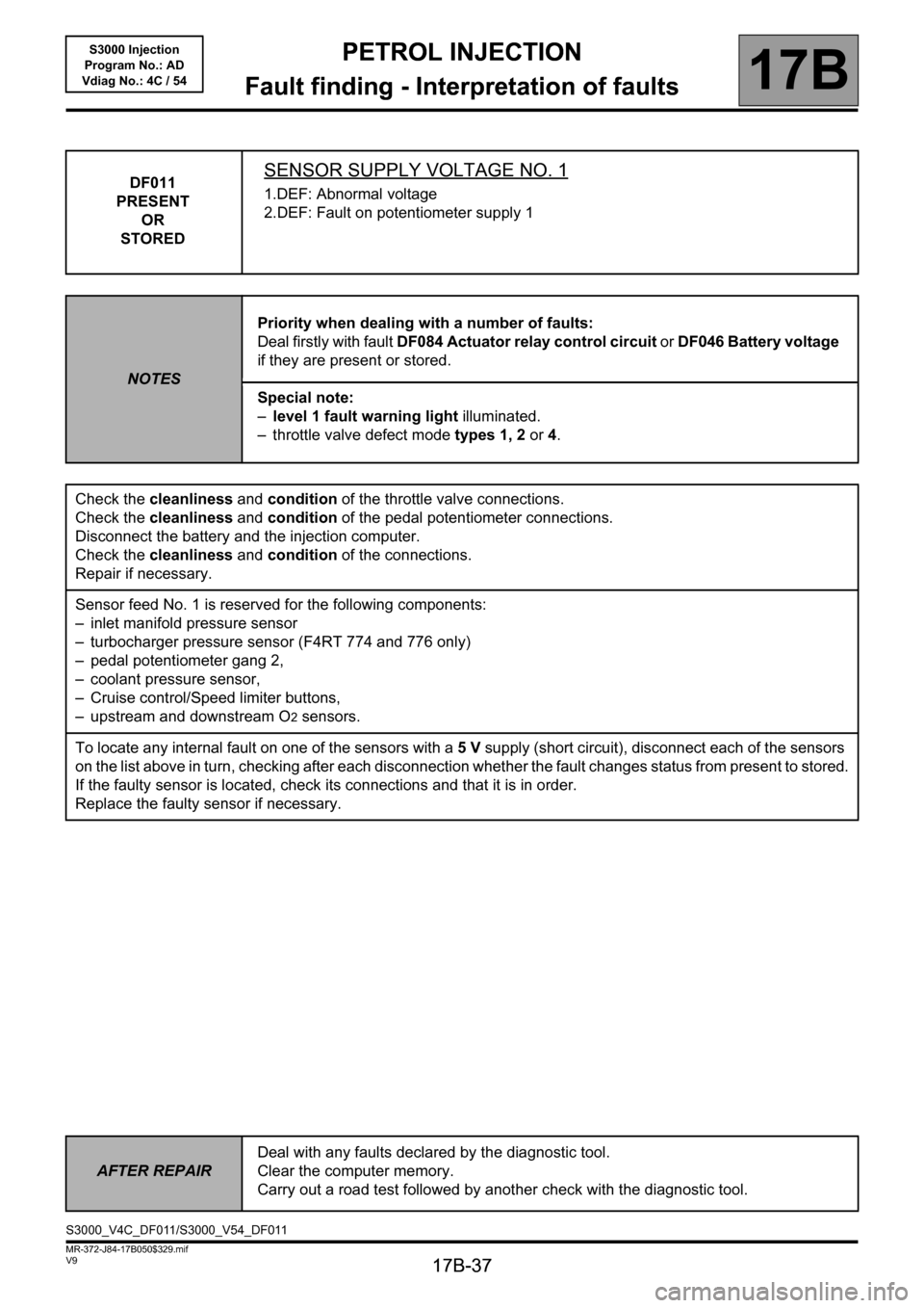
DF011
PRESENT
OR
STOREDSENSOR SUPPLY VOLTAGE NO. 1
1.DEF: Abnormal voltage
2.DEF: Fault on potentiometer supply 1
NOTESPriority when dealing with a number of faults:
Deal firstly with fault DF084 Actuator relay control circuit or DF046 Battery voltage
if they are present or stored.
Special note:
–level 1 fault warning light illuminated.
– throttle valve defect mode types 1, 2 or 4.
Check the cleanliness and condition of the throttle valve connections.
Check the cleanliness and condition of the pedal potentiometer connections.
Disconnect the battery and the injection computer.
Check the cleanliness and condition of the connections.
Repair if necessary.
Sensor feed No. 1 is reserved for the following components:
– inlet manifold pressure sensor
– turbocharger pressure sensor (F4RT 774 and 776 only)
– pedal potentiometer gang 2,
– coolant pressure sensor,
– Cruise control/Speed limiter buttons,
– upstream and downstream O
2 sensors.
To locate any internal fault on one of the sensors with a 5V supply (short circuit), disconnect each of the sensors
on the list above in turn, checking after each disconnection whether the fault changes status from present to stored.
If the faulty sensor is located, check its connections and that it is in order.
Replace the faulty sensor if necessary.
AFTER REPAIRDeal with any faults declared by the diagnostic tool.
Clear the computer memory.
Carry out a road test followed by another check with the diagnostic tool.
S3000_V4C_DF011/S3000_V54_DF011
Page 38 of 230

PETROL INJECTION
Fault finding - Interpretation of faults
17B
17B-38
PETROL INJECTION
Fault finding - Interpretation of faults
17B
17B-38V9 MR-372-J84-17B050$329.mif
S3000 Injection
Program No.: AD
Vdiag No.: 4C / 54
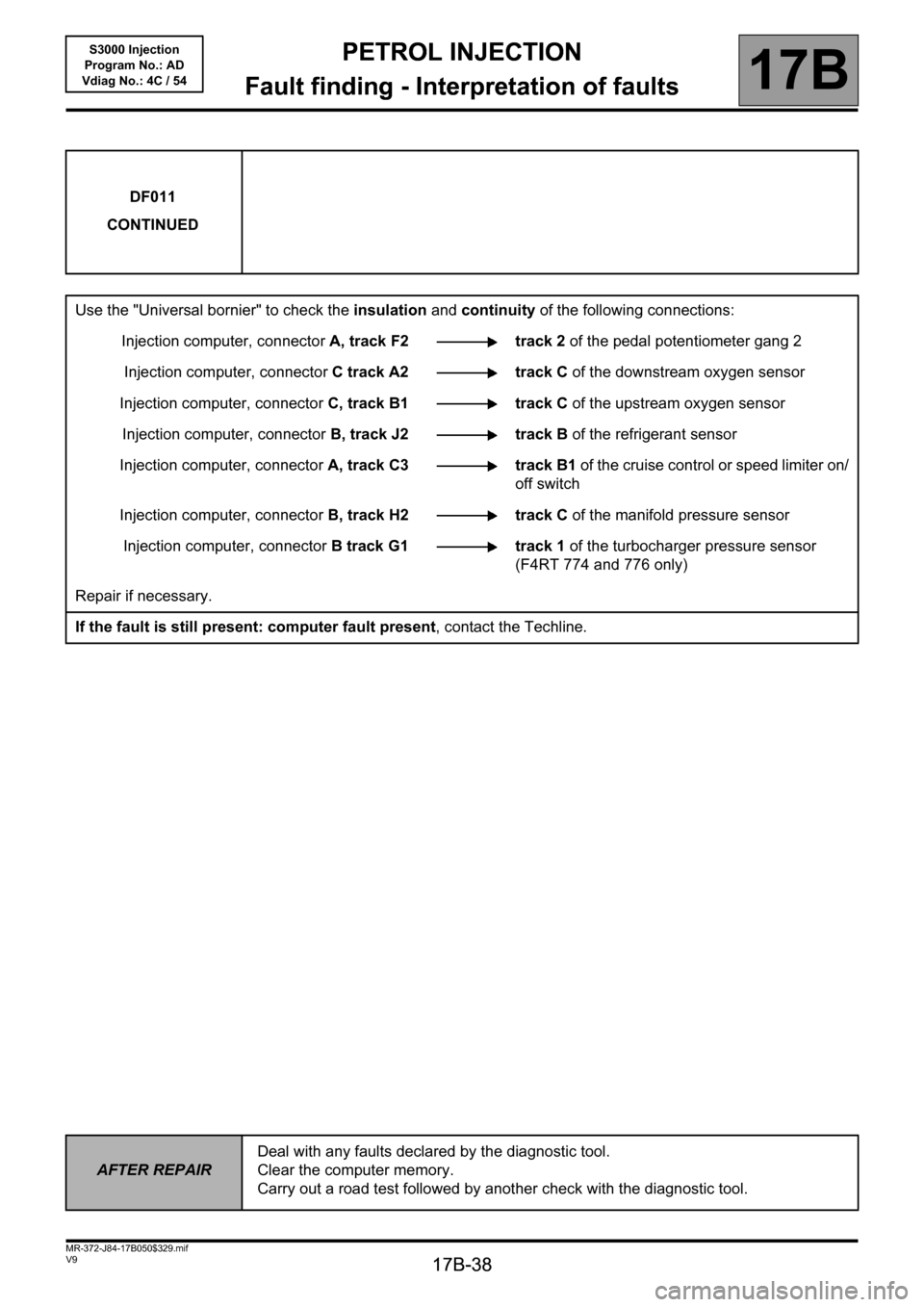
DF011
CONTINUED
Use the "Universal bornier" to check the insulation and continuity of the following connections:
Injection computer, connectorA, track F2 track 2 of the pedal potentiometer gang 2
Injection computer, connectorC track A2 track C of the downstream oxygen sensor
Injection computer, connectorC, track B1 track C of the upstream oxygen sensor
Injection computer, connectorB, track J2 track B of the refrigerant sensor
Injection computer, connectorA, track C3 track B1 of the cruise control or speed limiter on/
off switch
Injection computer, connectorB, track H2 track C of the manifold pressure sensor
Injection computer, connectorB track G1 track 1 of the turbocharger pressure sensor
(F4RT 774 and 776 only)
Repair if necessary.
If the fault is still present: computer fault present, contact the Techline.
AFTER REPAIRDeal with any faults declared by the diagnostic tool.
Clear the computer memory.
Carry out a road test followed by another check with the diagnostic tool.
Page 39 of 230

PETROL INJECTION
Fault finding - Interpretation of faults
17B
17B-39
PETROL INJECTION
Fault finding - Interpretation of faults
17B
17B-39V9 MR-372-J84-17B050$329.mif
S3000 Injection
Program No.: AD
Vdiag No.: 4C / 54
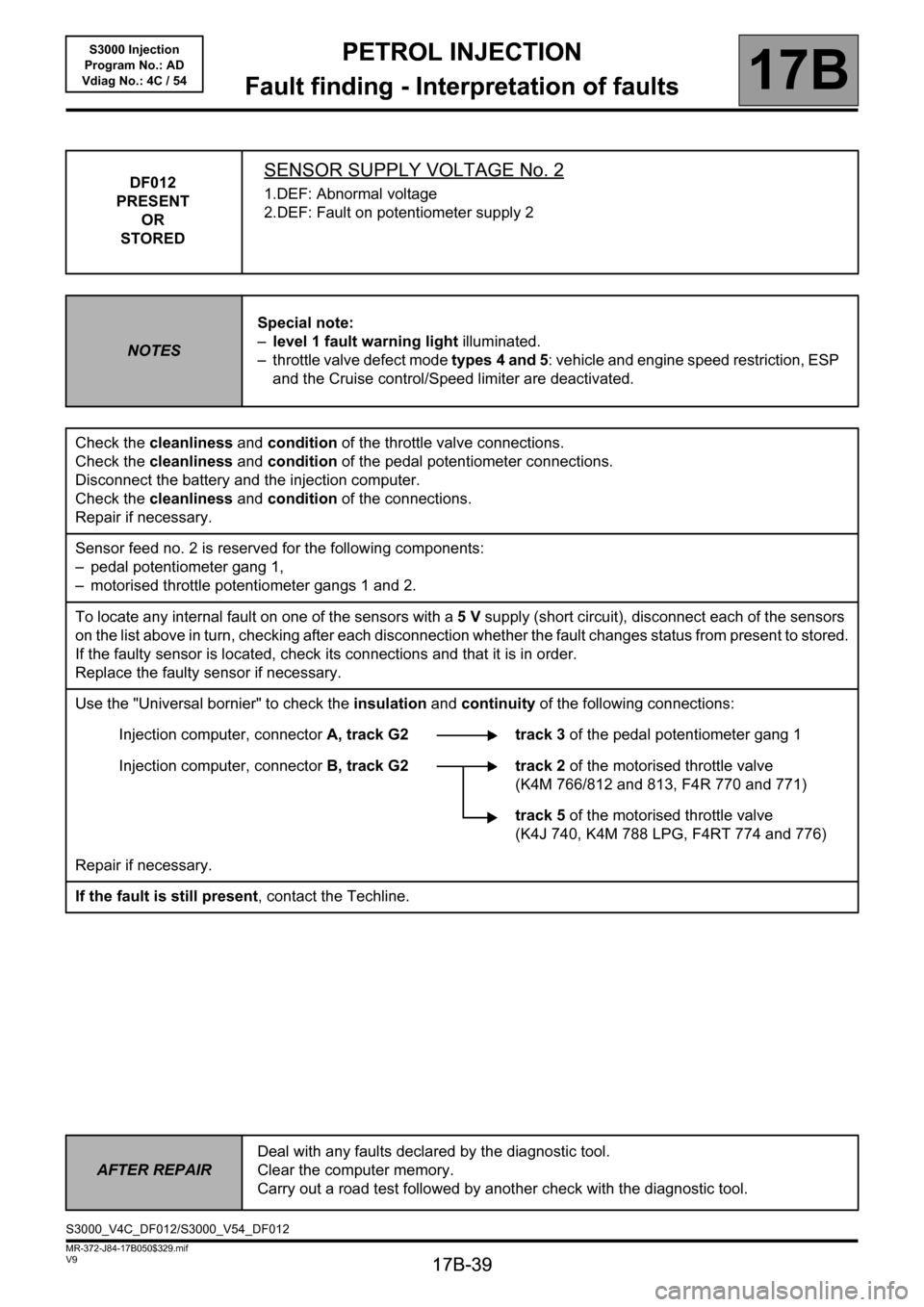
DF012
PRESENT
OR
STOREDSENSOR SUPPLY VOLTAGE No. 2
1.DEF: Abnormal voltage
2.DEF: Fault on potentiometer supply 2
NOTESSpecial note:
–level 1 fault warning light illuminated.
– throttle valve defect mode types 4 and 5: vehicle and engine speed restriction, ESP
and the Cruise control/Speed limiter are deactivated.
Check the cleanliness and condition of the throttle valve connections.
Check the cleanliness and condition of the pedal potentiometer connections.
Disconnect the battery and the injection computer.
Check the cleanliness and condition of the connections.
Repair if necessary.
Sensor feed no. 2 is reserved for the following components:
– pedal potentiometer gang 1,
– motorised throttle potentiometer gangs 1 and 2.
To locate any internal fault on one of the sensors with a 5V supply (short circuit), disconnect each of the sensors
on the list above in turn, checking after each disconnection whether the fault changes status from present to stored.
If the faulty sensor is located, check its connections and that it is in order.
Replace the faulty sensor if necessary.
Use the "Universal bornier" to check the insulation and continuity of the following connections:
Injection computer, connectorA, track G2 track 3 of the pedal potentiometer gang 1
Injection computer, connectorB, track G2 track 2 of the motorised throttle valve
(K4M 766/812 and 813, F4R 770 and 771)
track 5 of the motorised throttle valve
(K4J 740, K4M 788 LPG, F4RT 774 and 776)
Repair if necessary.
If the fault is still present, contact the Techline.
AFTER REPAIRDeal with any faults declared by the diagnostic tool.
Clear the computer memory.
Carry out a road test followed by another check with the diagnostic tool.
S3000_V4C_DF012/S3000_V54_DF012
Page 49 of 230

PETROL INJECTION
Fault finding - Interpretation of faults
17B
17B-49
PETROL INJECTION
Fault finding - Interpretation of faults
17B
17B-49V9 MR-372-J84-17B050$329.mif
S3000 Injection
Program No.: AD
Vdiag No.: 4C / 54
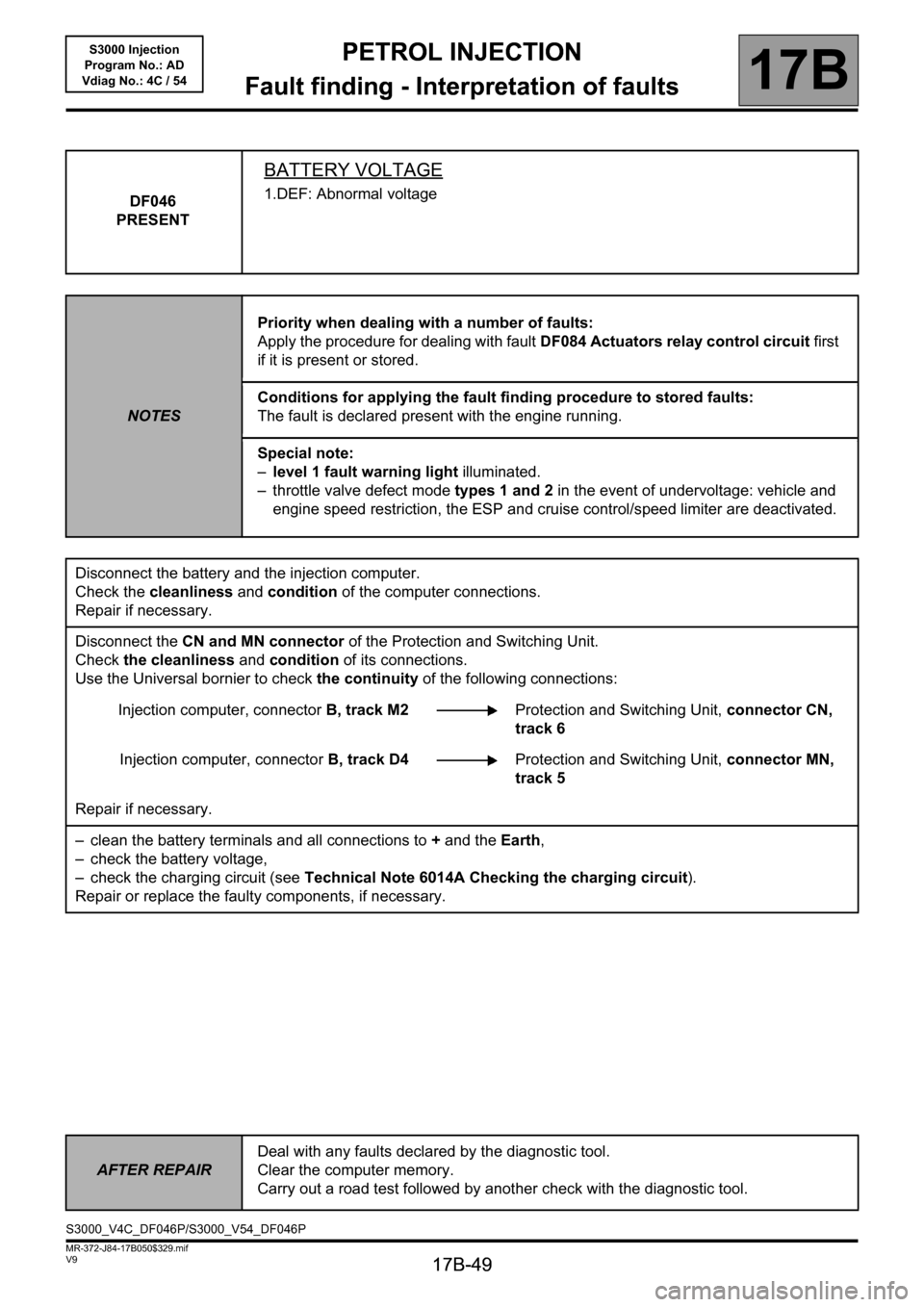
DF046
PRESENT
BATTERY VOLTAGE
1.DEF: Abnormal voltage
NOTESPriority when dealing with a number of faults:
Apply the procedure for dealing with fault DF084 Actuators relay control circuit first
if it is present or stored.
Conditions for applying the fault finding procedure to stored faults:
The fault is declared present with the engine running.
Special note:
–level 1 fault warning light illuminated.
– throttle valve defect mode types 1 and 2 in the event of undervoltage: vehicle and
engine speed restriction, the ESP and cruise control/speed limiter are deactivated.
Disconnect the battery and the injection computer.
Check the cleanliness and condition of the computer connections.
Repair if necessary.
Disconnect the CN and MN connector of the Protection and Switching Unit.
Check the cleanliness and condition of its connections.
Use the Universal bornier to check the continuity of the following connections:
Injection computer, connectorB, track M2Protection and Switching Unit, connector CN,
track 6
Injection computer, connectorB, track D4Protection and Switching Unit, connector MN,
track 5
Repair if necessary.
– clean the battery terminals and all connections to + and the Earth,
– check the battery voltage,
– check the charging circuit (see Technical Note 6014A Checking the charging circuit).
Repair or replace the faulty components, if necessary.
AFTER REPAIRDeal with any faults declared by the diagnostic tool.
Clear the computer memory.
Carry out a road test followed by another check with the diagnostic tool.
S3000_V4C_DF046P/S3000_V54_DF046P