camshaft sensor RENAULT SCENIC 2010 J95 / 3.G Petrol Injection S3000 Injection Owner's Manual
[x] Cancel search | Manufacturer: RENAULT, Model Year: 2010, Model line: SCENIC, Model: RENAULT SCENIC 2010 J95 / 3.GPages: 230, PDF Size: 0.92 MB
Page 174 of 230
PETROL INJECTION
Fault finding - Interpretation of statuses
17B
17B - 174
PETROL INJECTION
Fault finding - Interpretation of statuses
17B
17B - 174V9 MR-372-J84-17B050$611.mif
S3000 Injection
Program No.: AD
Vdiag No.: 4C / 54
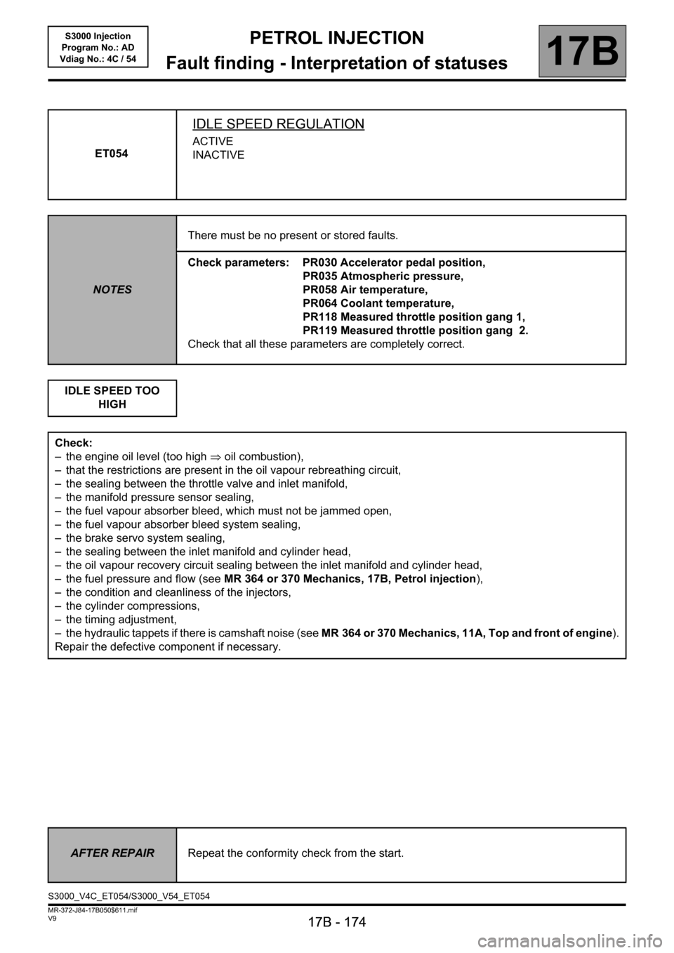
ET054
IDLE SPEED REGULATION
ACTIVE
INACTIVE
NOTESThere must be no present or stored faults.
Check parameters: PR030 Accelerator pedal position,
PR035 Atmospheric pressure,
PR058 Air temperature,
PR064 Coolant temperature,
PR118 Measured throttle position gang 1,
PR119 Measured throttle position gang 2.
Check that all these parameters are completely correct.
IDLE SPEED TOO
HIGH
Check:
– the engine oil level (too high ⇒ oil combustion),
– that the restrictions are present in the oil vapour rebreathing circuit,
– the sealing between the throttle valve and inlet manifold,
– the manifold pressure sensor sealing,
– the fuel vapour absorber bleed, which must not be jammed open,
– the fuel vapour absorber bleed system sealing,
– the brake servo system sealing,
– the sealing between the inlet manifold and cylinder head,
– the oil vapour recovery circuit sealing between the inlet manifold and cylinder head,
– the fuel pressure and flow (see MR 364 or 370 Mechanics, 17B, Petrol injection),
– the condition and cleanliness of the injectors,
– the cylinder compressions,
– the timing adjustment,
– the hydraulic tappets if there is camshaft noise (see MR 364 or 370 Mechanics, 11A, Top and front of engine).
Repair the defective component if necessary.
AFTER REPAIRRepeat the conformity check from the start.
S3000_V4C_ET054/S3000_V54_ET054
Page 177 of 230

PETROL INJECTION
Fault finding - Interpretation of statuses
17B
17B - 177
PETROL INJECTION
Fault finding - Interpretation of statuses
17B
17B - 177V9 MR-372-J84-17B050$611.mif
S3000 Injection
Program No.: AD
Vdiag No.: 4C / 54
ET056
CONTINUED 2
Check:
– the condition of the air filter,
– that the air inlet circuit is not blocked,
– the condition and conformity of the spark plugs,
– the sealing between the throttle valve and inlet manifold,
– the manifold pressure sensor sealing,
– the fuel vapour absorber bleed, which must not be jammed open,
– the fuel vapour absorber bleed system sealing,
– the brake servo system sealing,
– the cylinder head oil vapour recovery system sealing,
– the sealing between the inlet manifold and cylinder head,
– the exhaust pipe sealing between the cylinder head and catalytic converter.
– the fuel flow rate and pressure.
If the idle speed is not stable, check:
– the timing adjustment,
– the hydraulic tappets if there is camshaft noise (see MR 364 or 370 Mechanics, 11A, Top and front of engine),
– the cylinder compressions.
Drive the vehicle to check the repair.
Repair the defective components.
AFTER REPAIRRepeat the conformity check from the start.
Page 178 of 230
PETROL INJECTION
Fault finding - Interpretation of statuses
17B
17B - 178
PETROL INJECTION
Fault finding - Interpretation of statuses
17B
17B - 178V9 MR-372-J84-17B050$611.mif
S3000 Injection
Program No.: AD
Vdiag No.: 4C / 54
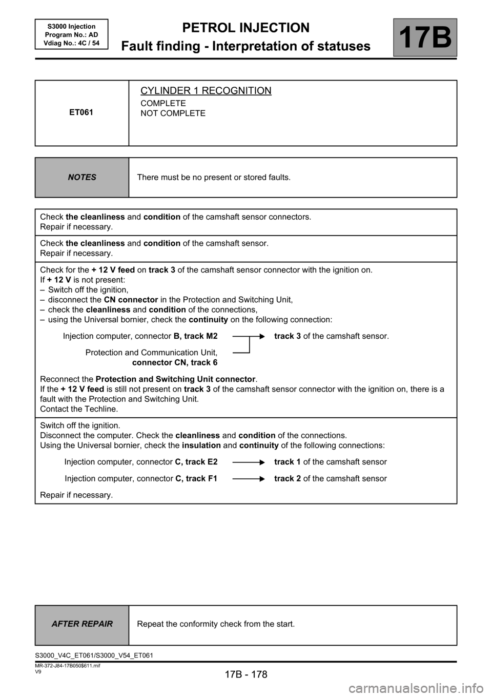
ET061
CYLINDER 1 RECOGNITION
COMPLETE
NOT COMPLETE
NOTESThere must be no present or stored faults.
Check the cleanliness and condition of the camshaft sensor connectors.
Repair if necessary.
Check the cleanliness and condition of the camshaft sensor.
Repair if necessary.
Check for the + 12 V feed on track 3 of the camshaft sensor connector with the ignition on.
If +12V is not present:
– Switch off the ignition,
– disconnect the CN connector in the Protection and Switching Unit,
– check the cleanliness and condition of the connections,
– using the Universal bornier, check the continuity on the following connection:
Injection computer, connectorB, track M2 track 3 of the camshaft sensor.
Protection and Communication Unit,
connector CN, track 6
Reconnect the Protection and Switching Unit connector.
If the + 12 V feed is still not present on track 3 of the camshaft sensor connector with the ignition on, there is a
fault with the Protection and Switching Unit.
Contact the Techline.
Switch off the ignition.
Disconnect the computer. Check the cleanliness and condition of the connections.
Using the Universal bornier, check the insulation and continuity of the following connections:
Injection computer, connectorC, track E2 track 1 of the camshaft sensor
Injection computer, connectorC, track F1 track 2 of the camshaft sensor
Repair if necessary.
AFTER REPAIRRepeat the conformity check from the start.
S3000_V4C_ET061/S3000_V54_ET061
Page 202 of 230

PETROL INJECTION
17B
17B - 202
17B
17B - 202V9 MR-372-J84-17B050$658.mif
S3000 Injection
Program No.: AD
Vdiag No.: 4C / 54PETROL INJECTION
Fault finding - Parameter summary table
* OCR: Opening Cycle Ratio
* appli.: applicationTool parameter Diagnostic tool title
PR010Idling speed regulation setpoint
PR014Idling speed correction
PR018Estimated air flow
PR030Accelerator pedal position
PR035Atmospheric pressure
PR037Refrigerant pressure
PR055Engine speed
PR058Air temperature
PR064Coolant temperature
PR074Battery voltage
PR089Vehicle speed
PR090Idling speed regulation programming value
PR091OCR* Theoretical idle speed regulation
PR093Camshaft dephaser measured position
PR095Anti-pinking correction
PR096Motorised throttle upper stop programmed value
PR097Motorised throttle lower stop programmed value
PR098Upstream oxygen sensor voltage
PR099Downstream oxygen sensor voltage
PR101Duration of injection
PR102Canister bleed solenoid valve OCR*
PR103Instantaneous fuel consumption
PR105OBD fault warning light lit mileage counter
PR106Mileage counter fault warning light lit
PR111Motorised throttle position corrected value
PR113Throttle lower stop after offset appli.*
PR116Motorised throttle corrected position setpoint
MR-372-J84-17B050$658.mif
Page 209 of 230

PETROL INJECTION
Fault finding - Interpretation of parameters
17B
17B - 209
PETROL INJECTION
Fault finding - Interpretation of parameters
17B
17B - 209V9 MR-372-J84-17B050$705.mif
S3000 Injection
Program No.: AD
Vdiag No.: 4C / 54
PR098
CONTINUED
If the fault is still present, replace the upstream oxygen sensor.
If the fault has still not been cured, continue with the checks.
Check:
– the condition of the air filter,
– that the air inlet circuit is not blocked,
– the condition and conformity of the spark plugs,
– that the catalytic converter is not clogged,
– the sealing between the throttle valve and inlet manifold,
– the manifold pressure sensor sealing,
– the fuel vapour absorber bleed, which must not be jammed open,'
– the fuel vapour absorber bleed system sealing,
– the brake servo system sealing,
– the cylinder head oil vapour recovery system sealing,
– the sealing between the inlet manifold and cylinder head,
– the exhaust pipe sealing between the cylinder head and catalytic converter.
– the fuel flow rate and pressure.
If the idle speed is not stable, check:
– the timing adjustment,
– the hydraulic tappets if there is camshaft noise (see MR 364 or 370 Mechanics, 11A, Top and front of engine),
– the cylinder compressions.
Drive the vehicle to check the repair.
AFTER REPAIRRepeat the conformity check from the start.
Page 213 of 230

PETROL INJECTION
17B
17B-213
PETROL INJECTION
17B
17B-213V9 MR-372-J84-17B050$752.mif
S3000 Injection
Program No.: AD
Vdiag No.: 4C / 54PETROL INJECTION
Fault finding - Command summary table
Tool command Diagnostic tool title
RZ001Fault memory
RZ005Programming
AC017Canister bleed solenoid valve
AC018Upstream O
2 sensor heating
AC019Downstream O
2 sensor heating
AC027Motorised throttle
AC079Actuator static test
AC195Electric coolant pump
AC253Camshaft dephaser: Normal control
AC254Camshaft dephaser: ON/OFF control
VP020Enter VIN
MR-372-J84-17B050$752.mif
Page 219 of 230
PETROL INJECTION
Fault finding - Test
17B
PETROL INJECTION
Fault finding - Test
17B
17B-219V9 MR-372-J84-17B050$846.mif
S3000 Injection
Program No.: AD
Vdiag No.: 4C / 54
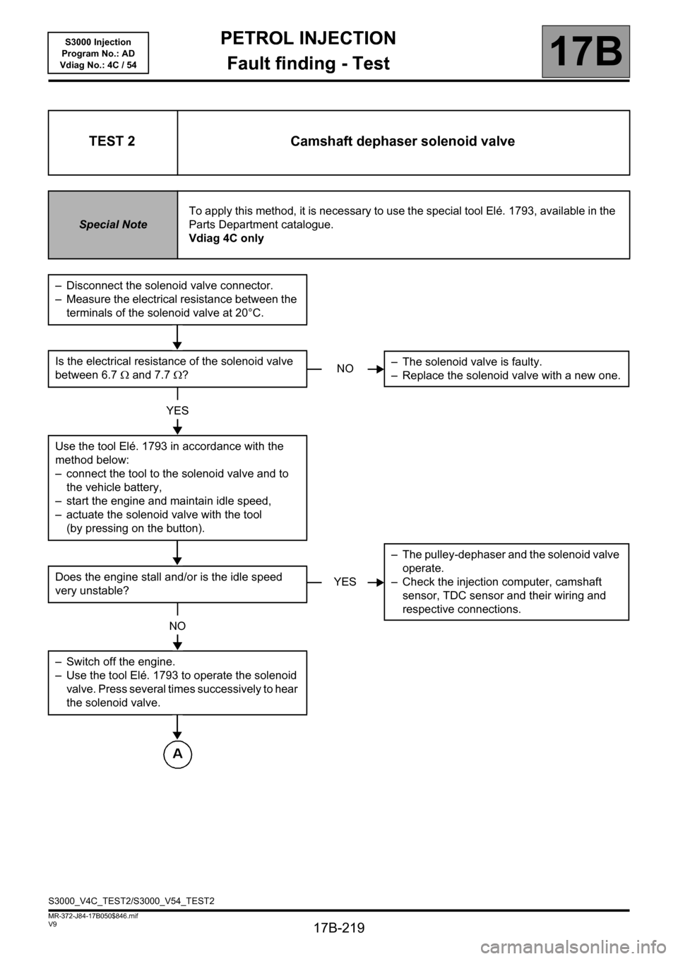
TEST 2 Camshaft dephaser solenoid valve
Special NoteTo apply this method, it is necessary to use the special tool Elé. 1793, available in the
Parts Department catalogue.
Vdiag 4C only
– Disconnect the solenoid valve connector.
– Measure the electrical resistance between the
terminals of the solenoid valve at 20°C.
Is the electrical resistance of the solenoid valve
between 6.7Ω and 7.7Ω?
YES
Use the tool Elé. 1793 in accordance with the
method below:
– connect the tool to the solenoid valve and to
the vehicle battery,
– start the engine and maintain idle speed,
– actuate the solenoid valve with the tool
(by pressing on the button).
Does the engine stall and/or is the idle speed
very unstable?
NO
– Switch off the engine.
– Use the tool Elé. 1793 to operate the solenoid
valve. Press several times successively to hear
the solenoid valve.
NO– The solenoid valve is faulty.
– Replace the solenoid valve with a new one.
YES– The pulley-dephaser and the solenoid valve
operate.
– Check the injection computer, camshaft
sensor, TDC sensor and their wiring and
respective connections.
S3000_V4C_TEST2/S3000_V54_TEST2
Page 221 of 230
PETROL INJECTION
Fault finding - Test
17B
PETROL INJECTION
Fault finding - Test
17B
17B-221V9 MR-372-J84-17B050$846.mif
S3000 Injection
Program No.: AD
Vdiag No.: 4C / 54
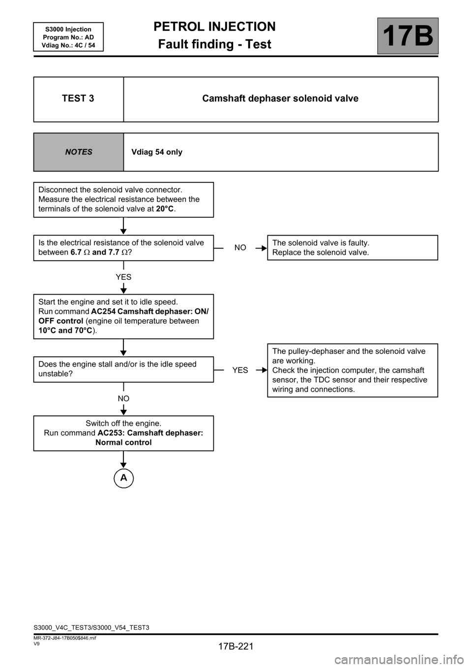
TEST 3 Camshaft dephaser solenoid valve
NOTESVdiag 54 only
Disconnect the solenoid valve connector.
Measure the electrical resistance between the
terminals of the solenoid valve at 20°C.
Is the electrical resistance of the solenoid valve
between 6.7 Ω and 7.7 Ω?
YES
Start the engine and set it to idle speed.
Run command AC254 Camshaft dephaser: ON/
OFF control (engine oil temperature between
10°C and 70°C).
Does the engine stall and/or is the idle speed
unstable?
NO
Switch off the engine.
Run command AC253: Camshaft dephaser:
Normal control
NOThe solenoid valve is faulty.
Replace the solenoid valve.
YESThe pulley-dephaser and the solenoid valve
are working.
Check the injection computer, the camshaft
sensor, the TDC sensor and their respective
wiring and connections.
S3000_V4C_TEST3/S3000_V54_TEST3
Page 228 of 230

PETROL INJECTION
Fault finding - Fault Finding Chart
17B
17B-228
PETROL INJECTION
Fault finding - Fault Finding Chart
17B
17B-228V9 MR-372-J84-17B050$940.mif
S3000 Injection
Program No.: AD
Vdiag No.:4C / 54
ALP 2 The engine will not start
NOTESFollow ALP 2 after a complete check with the diagnostic tool.
WARNING
Never drive the vehicle without checking first that there are no throttle valve
faults.
If the starter motor does not engage, there may be an engine immobiliser fault.
Carry out fault finding on the UCH (see87B, Passenger Compartment Connection Unit).
Check the condition of the battery.
Check the cleanliness, condition and tightness of the battery terminals.
Check that the battery is correctly earthed to the vehicle bodywork.
Check that the + battery leads are correctly connected.
Check that the starter motor is properly connected.
Check the starter is working properly (see Technical Note 6014A Checking the charging circuit).
Check the condition and conformity of the spark plugs.
Check the mounting, cleanliness and condition of the flywheel signal sensor.
Check the flywheel signal sensor air gap.
Check the condition of the flywheel.
Check that the air filter is not clogged.
Check that the air inlet circuit is not blocked.
Check that there is fuel in the tank (fuel sender fault).
Check that the tank vent is not blocked.
Check that the fuel is of the correct type.
Check that there are no leaks in the fuel system, from the tank to the injectors.
Check that there are no kinked hoses (especially after a removal operation).
Check the fuel flow rate and pressure.
Check the sealing of the injectors, and that they are working properly.
Check that the exhaust system is not blocked and the catalytic converter not clogged.
Check the timing setting.
Check the cylinder compressions.
Check the hydraulic tappets if there is camshaft noise.
AFTER REPAIRRepeat the conformity check from the start.
S3000_V4C_ALP2/S3000_V54_ALP2
Page 229 of 230
PETROL INJECTION
Fault finding - Fault Finding Chart
17B
17B-229
PETROL INJECTION
Fault finding - Fault Finding Chart
17B
17B-229V9 MR-372-J84-17B050$940.mif
S3000 Injection
Program No.: AD
Vdiag No.:4C / 54
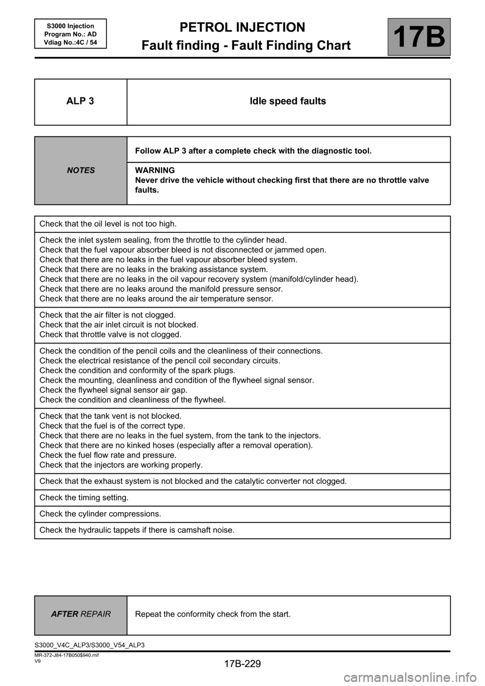
ALP 3 Idle speed faults
NOTESFollow ALP 3 after a complete check with the diagnostic tool.
WARNING
Never drive the vehicle without checking first that there are no throttle valve
faults.
Check that the oil level is not too high.
Check the inlet system sealing, from the throttle to the cylinder head.
Check that the fuel vapour absorber bleed is not disconnected or jammed open.
Check that there are no leaks in the fuel vapour absorber bleed system.
Check that there are no leaks in the braking assistance system.
Check that there are no leaks in the oil vapour recovery system (manifold/cylinder head).
Check that there are no leaks around the manifold pressure sensor.
Check that there are no leaks around the air temperature sensor.
Check that the air filter is not clogged.
Check that the air inlet circuit is not blocked.
Check that throttle valve is not clogged.
Check the condition of the pencil coils and the cleanliness of their connections.
Check the electrical resistance of the pencil coil secondary circuits.
Check the condition and conformity of the spark plugs.
Check the mounting, cleanliness and condition of the flywheel signal sensor.
Check the flywheel signal sensor air gap.
Check the condition and cleanliness of the flywheel.
Check that the tank vent is not blocked.
Check that the fuel is of the correct type.
Check that there are no leaks in the fuel system, from the tank to the injectors.
Check that there are no kinked hoses (especially after a removal operation).
Check the fuel flow rate and pressure.
Check that the injectors are working properly.
Check that the exhaust system is not blocked and the catalytic converter not clogged.
Check the timing setting.
Check the cylinder compressions.
Check the hydraulic tappets if there is camshaft noise.
AFTER REPAIRRepeat the conformity check from the start.
S3000_V4C_ALP3/S3000_V54_ALP3