relay RENAULT SCENIC 2010 J95 / 3.G Petrol Injection S3000 Injection Owner's Guide
[x] Cancel search | Manufacturer: RENAULT, Model Year: 2010, Model line: SCENIC, Model: RENAULT SCENIC 2010 J95 / 3.GPages: 230, PDF Size: 0.92 MB
Page 103 of 230

PETROL INJECTION
Fault finding - Interpretation of faults
17B
17B-103
PETROL INJECTION
Fault finding - Interpretation of faults
17B
17B-103V9 MR-372-J84-17B050$423.mif
S3000 Injection
Program No.: AD
Vdiag No.: 4C / 54
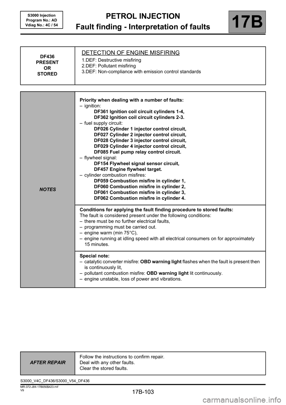
DF436
PRESENT
OR
STOREDDETECTION OF ENGINE MISFIRING
1.DEF: Destructive misfiring
2.DEF: Pollutant misfiring
3.DEF: Non-compliance with emission control standards
NOTESPriority when dealing with a number of faults:
– ignition:
DF361 Ignition coil circuit cylinders 1-4,
DF362 Ignition coil circuit cylinders 2-3.
– fuel supply circuit:
DF026 Cylinder 1 injector control circuit,
DF027 Cylinder 2 injector control circuit,
DF028 Cylinder 3 injector control circuit,
DF029 Cylinder 4 injector control circuit,
DF085 Fuel pump relay control circuit.
– flywheel signal:
DF154 Flywheel signal sensor circuit,
DF457 Engine flywheel target.
– cylinder combustion misfires:
DF059 Combustion misfire in cylinder 1,
DF060 Combustion misfire in cylinder 2,
DF061 Combustion misfire in cylinder 3,
DF062 Combustion misfire in cylinder 4.
Conditions for applying the fault finding procedure to stored faults:
The fault is considered present under the following conditions:
– there must be no further electrical faults,
– programming must be carried out.
– engine warm (min 75°C),
– engine running at idling speed with all electrical consumers on for approximately
15 minutes.
Special note:
– catalytic converter misfire: OBD warning light flashes when the fault is present then
is continuously lit,
– pollutant combustion misfire: OBD warning light lit continuously.
– engine unstable, loss of power and vibrations.
AFTER REPAIRFollow the instructions to confirm repair.
Deal with any other faults.
Clear the stored faults.
S3000_V4C_DF436/S3000_V54_DF436
Page 107 of 230

PETROL INJECTION
Fault finding - Interpretation of faults
17B
17B-107
PETROL INJECTION
Fault finding - Interpretation of faults
17B
17B-107V9 MR-372-J84-17B050$423.mif
S3000 Injection
Program No.: AD
Vdiag No.: 4C / 54
DF570
PRESENT
OR
STOREDCOOLANT PUMP RELAY
CO: Open circuit
CC.0: Short circuit to earth
CC.1: Short-circuit to + 12 V
NOTESConditions for applying the fault finding procedure to stored faults:
The fault is declared present when the engine is running or on command AC195
Electric coolant pump.
Check the cleanliness, condition and fitting of the coolant pump.
Top up the coolant if necessary.
If the fault is still present, manipulate the harness to see if the status changes.
Look for any harness damage, and check the condition and connection points of the injection computer and the
coolant pump connectors.
Repair if necessary.
If the fault is still present, check for +12V on track 2 of the coolant pump.
If +12V is not present on track 2 of the coolant pump, check the following connection for insulation, continuity
and the absence of interference resistance:
Coolant pump track 2 track 6, connector CN, of the Protection and
Switching Unit
Repair if necessary.
If the fault is still present, check the insulation, continuity and the absence of interference resistance on the
following connection:
Computer, connectorB, track L4 track 1 of the coolant pump
Repair if necessary.
If the fault is still present, check that the resistance between tracks 1 and 2 of the coolant pump is neither zero
nor infinite.
Replace the coolant pump if necessary.
If the fault is still present, deal with the other faults then proceed to the conformity check.
AFTER REPAIRFollow the instructions to confirm repair.
Deal with any other faults.
Clear the stored faults.
S3000_V4C_DF570/S3000_V54_DF570
Page 108 of 230

PETROL INJECTION
Fault finding - Interpretation of faults
17B
17B-108
PETROL INJECTION
Fault finding - Interpretation of faults
17B
17B-108V9 MR-372-J84-17B050$423.mif
S3000 Injection
Program No.: AD
Vdiag No.: 4C / 54
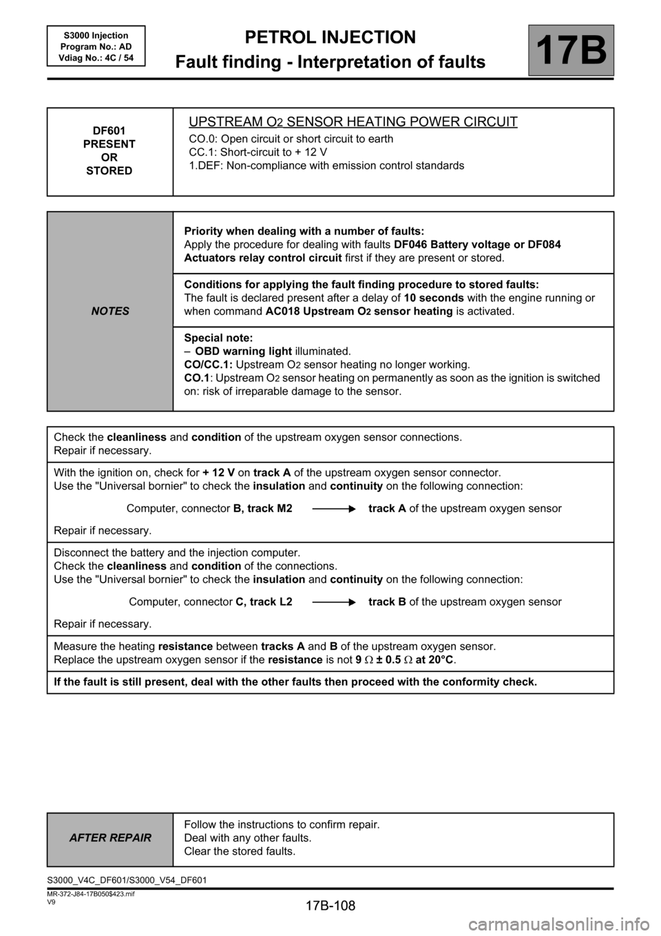
DF601
PRESENT
OR
STOREDUPSTREAM O2 SENSOR HEATING POWER CIRCUIT
CO.0: Open circuit or short circuit to earth
CC.1: Short-circuit to + 12 V
1.DEF: Non-compliance with emission control standards
NOTESPriority when dealing with a number of faults:
Apply the procedure for dealing with faults DF046 Battery voltage or DF084
Actuators relay control circuit first if they are present or stored.
Conditions for applying the fault finding procedure to stored faults:
The fault is declared present after a delay of 10 seconds with the engine running or
when command AC018 Upstream O2 sensor heating is activated.
Special note:
–OBD warning light illuminated.
CO/CC.1: Upstream O
2 sensor heating no longer working.
CO.1: Upstream O
2 sensor heating on permanently as soon as the ignition is switched
on: risk of irreparable damage to the sensor.
Check the cleanliness and condition of the upstream oxygen sensor connections.
Repair if necessary.
With the ignition on, check for + 12 V on track A of the upstream oxygen sensor connector.
Use the "Universal bornier" to check the insulation and continuity on the following connection:
Computer, connectorB, track M2 track A of the upstream oxygen sensor
Repair if necessary.
Disconnect the battery and the injection computer.
Check the cleanliness and condition of the connections.
Use the "Universal bornier" to check the insulation and continuity on the following connection:
Computer, connectorC, track L2 track B of the upstream oxygen sensor
Repair if necessary.
Measure the heating resistance between tracks A and B of the upstream oxygen sensor.
Replace the upstream oxygen sensor if the resistance is not 9Ω ± 0.5Ω at 20°C.
If the fault is still present, deal with the other faults then proceed with the conformity check.
AFTER REPAIRFollow the instructions to confirm repair.
Deal with any other faults.
Clear the stored faults.
S3000_V4C_DF601/S3000_V54_DF601
Page 109 of 230

PETROL INJECTION
Fault finding - Interpretation of faults
17B
17B-109
PETROL INJECTION
Fault finding - Interpretation of faults
17B
17B-109V9 MR-372-J84-17B050$423.mif
S3000 Injection
Program No.: AD
Vdiag No.: 4C / 54
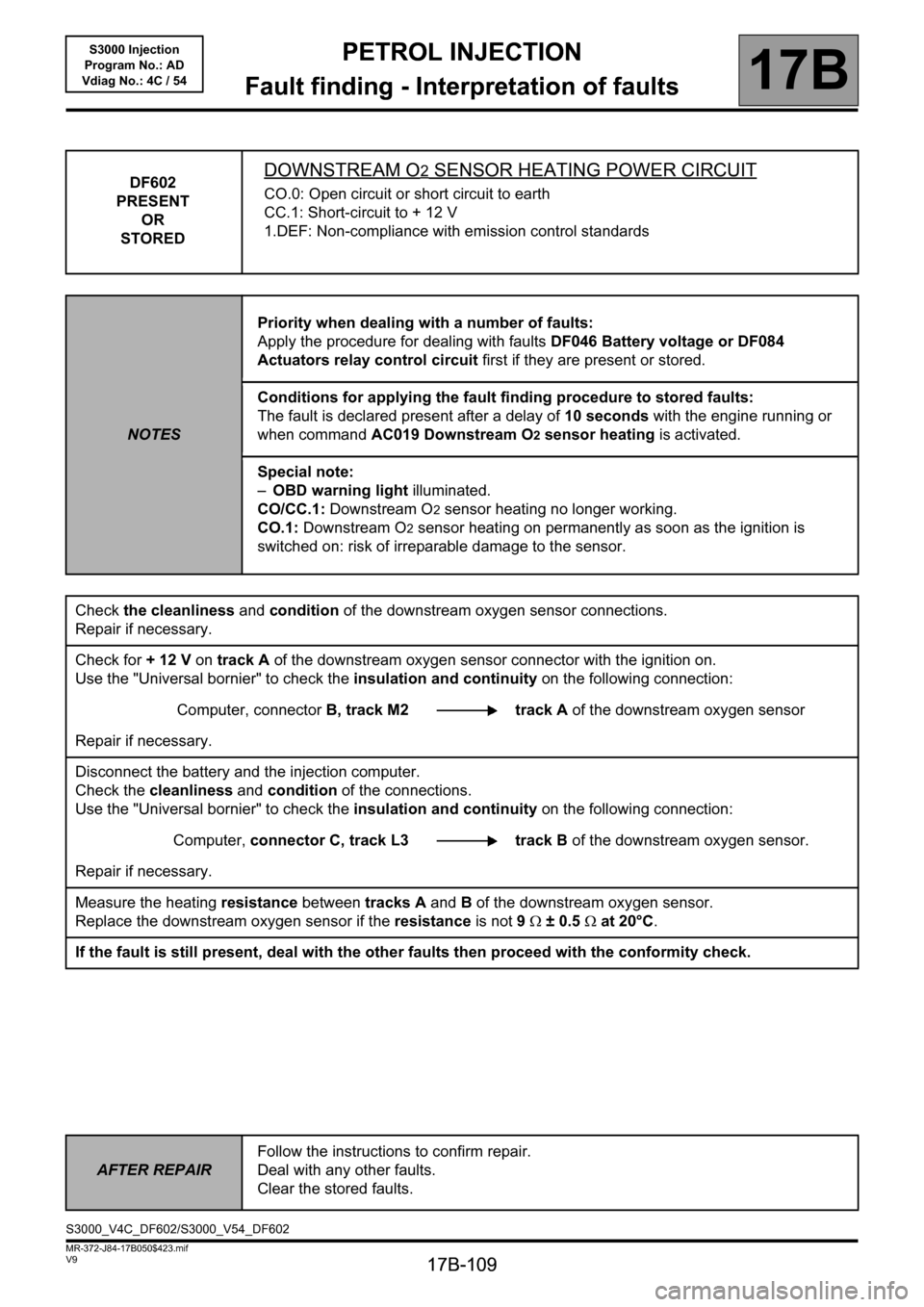
DF602
PRESENT
OR
STOREDDOWNSTREAM O2 SENSOR HEATING POWER CIRCUIT
CO.0: Open circuit or short circuit to earth
CC.1: Short-circuit to + 12 V
1.DEF: Non-compliance with emission control standards
NOTESPriority when dealing with a number of faults:
Apply the procedure for dealing with faults DF046 Battery voltage or DF084
Actuators relay control circuit first if they are present or stored.
Conditions for applying the fault finding procedure to stored faults:
The fault is declared present after a delay of 10 seconds with the engine running or
when command AC019 Downstream O2 sensor heating is activated.
Special note:
–OBD warning light illuminated.
CO/CC.1: Downstream O
2 sensor heating no longer working.
CO.1: Downstream O
2 sensor heating on permanently as soon as the ignition is
switched on: risk of irreparable damage to the sensor.
Check the cleanliness and condition of the downstream oxygen sensor connections.
Repair if necessary.
Check for + 12 V on track A of the downstream oxygen sensor connector with the ignition on.
Use the "Universal bornier" to check the insulation and continuity on the following connection:
Computer, connectorB, track M2 track A of the downstream oxygen sensor
Repair if necessary.
Disconnect the battery and the injection computer.
Check the cleanliness and condition of the connections.
Use the "Universal bornier" to check the insulation and continuity on the following connection:
Computer, connector C, track L3 track Bof the downstream oxygen sensor.
Repair if necessary.
Measure the heating resistance between tracks A and B of the downstream oxygen sensor.
Replace the downstream oxygen sensor if the resistance is not 9Ω ± 0.5Ω at 20°C.
If the fault is still present, deal with the other faults then proceed with the conformity check.
AFTER REPAIRFollow the instructions to confirm repair.
Deal with any other faults.
Clear the stored faults.
S3000_V4C_DF602/S3000_V54_DF602
Page 122 of 230

PETROL INJECTION
Fault finding - Conformity check
17B
17B-122
PETROL INJECTION
Fault finding - Conformity check
17B
17B-122V9 MR-372-J84-17B050$470.mif
S3000 Injection
Program No.: AD
Vdiag No.: 4C / 54
SUB FUNCTION: (TURBO/INLET) (continued):
OCR: Opening Cycle Ratio
NOTESOnly check the conformity after a complete check with the diagnostic tool. The values
shown in this conformity check are given as a guide.
Application conditions: Engine off, ignition on.
Order FunctionParameter or Status
Checked or ActionDisplay and notes Fault finding
8 Air flow PR018:Estimated air
flowIndicates the air flow
value estimated by the
motorised throttle
valve.
PR018= 0kg/hIf there is a fault, apply the
interpretation of faults
DF095 Throttle
potentiometer circuit
gang 1 and DF096
Throttle potentiometer
circuit gang 2.
9
Camshaft
dephaser (Only
on K4M
engines)ET083:Camshaft
dephaser in
defect modeSTATUS 1: This defect
mode covers all faults
that affect the dephaser
position measurement.
The dephaser is set to the
lower stop and the
camshaft angle
measurement is forced
to 0. Tooth signal fault.
STATUS 2: This defect
mode covers all faults
that affect the dephaser
(pulley and solenoid
valve). The dephaser is
set to the low stop.
NOFor STATUS 1, carry out
a camshaft signal/tooth
consistency diagnostic.
For STATUS 2, carry out
fault finding on the
camshaft dephaser
position.
10 PR094:Camshaft
dephaser OCR
setpointShows required camshaft
offset value (in %).
PR094 = 0%
WITHOUT
11 ET086:Camshaft
dephaser
controlACTIVE
INACTIVE
12electric coolant
pumpAC195:Electric coolant
pumpThe pump should be
heard operatingIn the event of a fault,
apply interpretation of
DF570 Coolant pump
relay.
Page 126 of 230

PETROL INJECTION
Fault finding - Conformity check
17B
17B-126
PETROL INJECTION
Fault finding - Conformity check
17B
17B-126V9 MR-372-J84-17B050$470.mif
S3000 Injection
Program No.: AD
Vdiag No.: 4C / 54
SUB-FUNCTION: FUEL CIRCUIT (continued 3):
NOTESOnly check the conformity after a complete check with the diagnostic tool. The values
shown in this conformity check are given as a guide.
Application conditions: Engine off, ignition on.
Order FunctionParameter or Status
Checked or ActionDisplay and notes Fault finding
13 Fuel pump ET047:Fuel pump
control circuitACTIVE for 1 second when the
ignition is switched on then
INACTIVEIf ACTIVE, apply
the interpretation
of DF085 Fuel
pump relay
control circuit
(when the +
after ignition
feed is turned
on, the pump
control circuit is
ACTIVE for
1 second then
becomes
INACTIVE).
14
IN LPG
ACTIVATED
MODEET561:Operating
modePetrol
Ignition on
In the event of a
fault, (see 17C,
3000 LPG
injection). 15 ET067:LPG readyWith LPG YESWithout LPG
NO by default
16 ET073:Conditions for
switching to
LPG modeWith LPG
AUTHORISEDWithout LPG
INHIBITED by
default
17 ET068:LPG tank
emptyWith LPG "NO"Without LPG
NO by default
18 ET066:LPG faultWith LPG "NO"Without LPG
NO by default
19 ET071:Transition
from petrol
mode to LPG
modeWith LPG
COMPLETEWithout LPG
COMPLETE by
default
20 ET072:Transition
from LPG
mode to petrol
modeWith LPG
IN PROGRESSWithout LPG
COMPLETE by
default
Page 134 of 230

PETROL INJECTION
Fault finding - Conformity check
17B
17B-134
PETROL INJECTION
Fault finding - Conformity check
17B
17B-134V9 MR-372-J84-17B050$470.mif
S3000 Injection
Program No.: AD
Vdiag No.: 4C / 54
SUB-FUNCTION: IGNITION/PREHEATING (continued 1):
NOTESOnly check the conformity after a complete check with the diagnostic tool. The values
shown in this conformity check are given as a guide.
Application conditions: Engine off, ignition on.
Order FunctionParameter or Status Checked
or ActionDisplay and notes Fault finding
9ET581:Petrol combustion
misfire fault findingINACTIVEIn the event of a fault,
apply interpretation of
faults DF059
Combustion misfire
in cylinder 1, DF060
Combustion misfire
in cylinder 2, DF061
Combustion misfire
in cylinder 3, DF062
Combustion misfire
in cylinder 4. 10
Combustion
misfireET057:Misfiring on cylinder 1NO
11 ET058:Misfiring on cylinder 2NO
12 ET059:Misfiring on cylinder 3NO
13 ET060:Misfiring on cylinder 4NO
14 ActuatorsAC079
:Actuator static testAll the actuators must
be operated (fuel
pump relay, electric
coolant pump on
F4RT, downstream
and upstream sensor
heating, motorised
throttle)In the event of a fault,
apply interpretation of
fault associated with
the actuators
concerned.
Page 135 of 230

PETROL INJECTION
Fault finding - Conformity check
17B
17B-135
PETROL INJECTION
Fault finding - Conformity check
17B
17B-135V9 MR-372-J84-17B050$470.mif
S3000 Injection
Program No.: AD
Vdiag No.: 4C / 54
IGNITION/PREHEATING SUB-FUNCTION (continued 2):
NOTESOnly check the conformity after a complete check with the diagnostic tool. The values
shown in this conformity check are given as a guide.
Application conditions: Engine off, ignition on.
Order FunctionParameter or Status Checked
or ActionDisplay and notes Fault finding
15
Combustion
misfire
GasET582:LPG combustion
misfire fault findingINACTIVEIn the event of a fault,
apply interpretation of
faults DF635
Combustion misfire
in LPG cylinder 1,
DF636 Combustion
misfire in LPG
cylinder 2, DF637
Combustion misfire
in LPG cylinder 3,
DF638 Combustion
misfire in LPG
cylinder 4. 16 ET583:LPG cylinder 1
combustion misfireNO
17 ET584:LPG cylinder 2
combustion misfireNO
18 ET585:LPG cylinder 3
combustion misfireNO
19 ET586:LPG cylinder 4
combustion misfireNO
20 Actuators AC079:Actuator static testAll the actuators
must be operated
(fuel pump relay,
electric coolant
pump on F4RT,
downstream and
upstream sensor
heating, motorised
throttle)In the event of a fault,
apply interpretation of
fault associated with
the actuators
concerned.
Page 142 of 230

PETROL INJECTION
Fault finding - Conformity check
17B
17B-142
PETROL INJECTION
Fault finding - Conformity check
17B
17B-142V9 MR-372-J84-17B050$470.mif
S3000 Injection
Program No.: AD
Vdiag No.: 4C / 54
STARTING SUB-FUNCTION:
NOTESOnly check the conformity after a complete check with the diagnostic tool. The values
shown in this conformity check are given as a guide.
Application conditions: Engine off, ignition on.
Order FunctionParameter or Status
Checked or ActionDisplay and notes Fault finding
1StartingET076:StartingAUTHORISEDAuthorisation to start is
given once the petrol
pump is pressurised
and if the motorised
throttle has emerged
from the stop and limp-
home position
programming phase.
2Actuator relay
controlET048:Actuator relay
controlACTIVEIf INACTIVE, apply the
interpretation of DF084
Actuator relay control
circuit.
3 Battery voltage PR074:Battery voltage11 V < PR074 < 15 VIn the event of a fault,
apply the interpretation of
DF046 Battery voltage.
4 Impact signal ET077:Impact
detectedNOIn the event of a fault,
run a multiplex network
test using the
diagnostic tool; then, if
the test is OK, carry out
fault finding on the
airbag computer.
Page 146 of 230

PETROL INJECTION
Fault finding - Conformity check
17B
17B-146
PETROL INJECTION
Fault finding - Conformity check
17B
17B-146V9 MR-372-J84-17B050$470.mif
S3000 Injection
Program No.: AD
Vdiag No.: 4C / 54
SUB FUNCTION: AIR CIRCUIT (TURBO/INLET) (continued):
OCR: Opening Cycle Ratio
NOTESOnly perform this conformity check after a complete check with the diagnostic tool.
The values shown in this conformity check are given as a guide.
Application conditions: Engine warm, idling.
Order FunctionParameter or Status
Checked or ActionDisplay and notes Fault finding
8 Air flow PR018:Estimated air
flowIndicates the air flow
value estimated by the
motorised throttle
valve.If there is a fault, apply the
interpretation of faults
DF095 Throttle
potentiometer circuit
gang 1 and DF096
Throttle potentiometer
circuit gang 2.
9
Camshaft
dephaser (Only
on K4M
engines)ET083:Camshaft
dephaser in
defect modeSTATUS 1: This defect
mode covers all faults
that affect the dephaser
position measurement.
The dephaser is set to the
lower stop and the
camshaft angle
measurement is forced
to 0. Tooth signal fault.
STATUS 2: This defect
mode covers all faults
that affect the dephaser
(pulley and solenoid
valve). The dephaser is
set to the low stop.
NOFor STATUS 1, carry out
a camshaft signal/tooth
consistency diagnostic.
For STATUS 2, carry out
fault finding on the
camshaft dephaser
position.
10 PR094:Camshaft
dephaser OCR
setpointShows required camshaft
offset value (in %).
WITHOUT
11 ET086:Camshaft
dephaser
controlACTIVE
INACTIVE
12electric coolant
pumpAC195:Electric coolant
pumpThe pump should be
heard operatingIn the event of a fault,
apply interpretation of
DF570 Coolant pump
relay.