light RENAULT SCENIC 2010 J95 / 3.G Petrol Injection S3000 Injection Repair Manual
[x] Cancel search | Manufacturer: RENAULT, Model Year: 2010, Model line: SCENIC, Model: RENAULT SCENIC 2010 J95 / 3.GPages: 230, PDF Size: 0.92 MB
Page 144 of 230
PETROL INJECTION
Fault finding - Conformity check
17B
17B-144
PETROL INJECTION
Fault finding - Conformity check
17B
17B-144V9 MR-372-J84-17B050$470.mif
S3000 Injection
Program No.: AD
Vdiag No.: 4C / 54
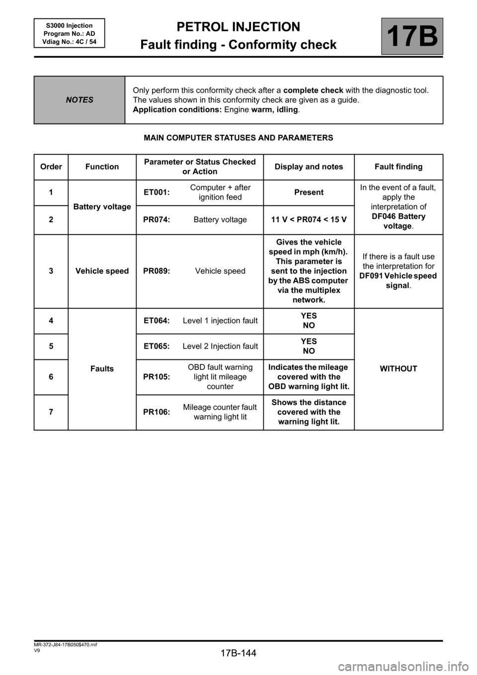
MAIN COMPUTER STATUSES AND PARAMETERS
NOTESOnly perform this conformity check after a complete check with the diagnostic tool.
The values shown in this conformity check are given as a guide.
Application conditions: Engine warm, idling.
Order FunctionParameter or Status Checked
or ActionDisplay and notes Fault finding
1
Battery voltageET001:Computer + after
ignition feedPresentIn the event of a fault,
apply the
interpretation of
DF046 Battery
voltage. 2 PR074:Battery voltage11 V < PR074 < 15 V
3 Vehicle speed PR089:Vehicle speedGives the vehicle
speed in mph (km/h).
This parameter is
sent to the injection
by the ABS computer
via the multiplex
network.If there is a fault use
the interpretation for
DF091 Vehicle speed
signal.
4
FaultsET064:Level 1 injection faultYES
NO
WITHOUT 5ET065:Level 2 Injection faultYES
NO
6 PR105:OBD fault warning
light lit mileage
counterIndicates the mileage
covered with the
OBD warning light lit.
7 PR106:Mileage counter fault
warning light litShows the distance
covered with the
warning light lit.
Page 152 of 230
PETROL INJECTION
Fault finding - Conformity check
17B
17B-152
PETROL INJECTION
Fault finding - Conformity check
17B
17B-152V9 MR-372-J84-17B050$517.mif
S3000 Injection
Program No.: AD
Vdiag No.: 4C / 54
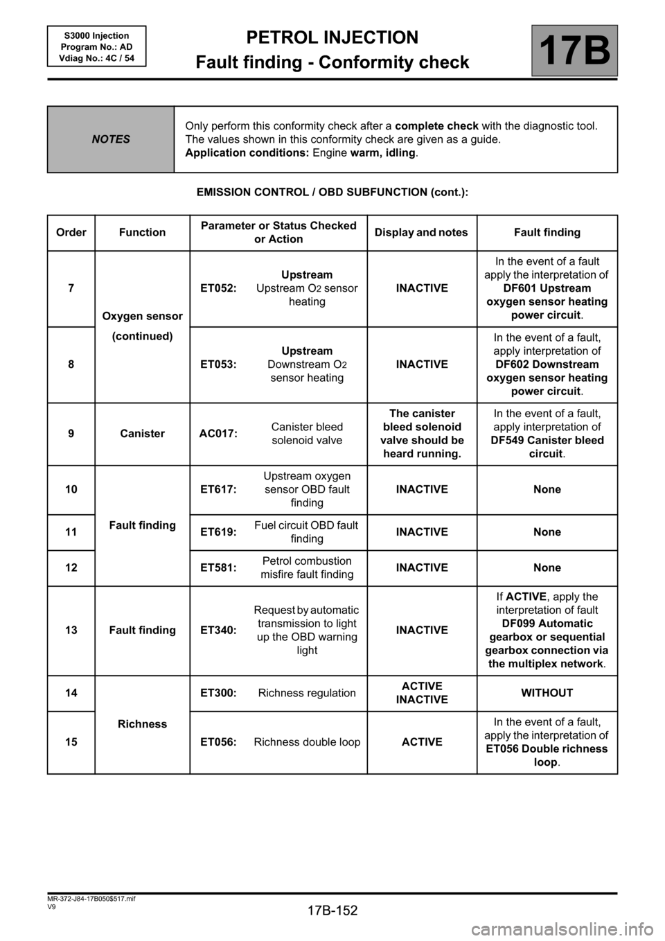
EMISSION CONTROL / OBD SUBFUNCTION (cont.):
NOTESOnly perform this conformity check after a complete check with the diagnostic tool.
The values shown in this conformity check are given as a guide.
Application conditions: Engine warm, idling.
Order FunctionParameter or Status Checked
or ActionDisplay and notes Fault finding
7
Oxygen sensor
(continued)ET052:Upstream
Upstream O
2 sensor
heatingINACTIVEIn the event of a fault
apply the interpretation of
DF601 Upstream
oxygen sensor heating
power circuit.
8ET053:Upstream
Downstream O
2
sensor heatingINACTIVEIn the event of a fault,
apply interpretation of
DF602 Downstream
oxygen sensor heating
power circuit.
9CanisterAC017:Canister bleed
solenoid valveThe canister
bleed solenoid
valve should be
heard running.In the event of a fault,
apply interpretation of
DF549 Canister bleed
circuit.
10
Fault findingET617:Upstream oxygen
sensor OBD fault
findingINACTIVE None
11 ET619:Fuel circuit OBD fault
findingINACTIVE None
12 ET581:Petrol combustion
misfire fault findingINACTIVE None
13 Fault finding ET340:Request by automatic
transmission to light
up the OBD warning
lightINACTIVEIf ACTIVE, apply the
interpretation of fault
DF099 Automatic
gearbox or sequential
gearbox connection via
the multiplex network.
14
RichnessET300:Richness regulationACTIVE
INACTIVEWITHOUT
15 ET056:Richness double loopACTIVEIn the event of a fault,
apply the interpretation of
ET056 Double richness
loop.
Page 169 of 230

PETROL INJECTION
Fault finding - Status summary table
17B
17B - 169
PETROL INJECTION
Fault finding - Status summary table
17B
17B - 169V9 MR-372-J84-17B050$564.mif
S3000 Injection
Program No.: AD
Vdiag No.: 4C / 54
Tool status Diagnostic tool title
ET076Starting
ET077Impact detected
ET079Air conditioning present
ET081Accelerator pedal position
ET082Motorised throttle position
ET083Camshaft dephaser in defect mode
ET086Camshaft dephaser control
ET088Compressor actuation request
ET089Flywheel target programming
ET111RCH number set
ET112RCH cut-off
ET300Richness regulation
ET340Request by automatic transmission to light up the OBD warning light
ET405Clutch pedal switch
ET415Deactivation of cruise control/speed limiter
ET561Operating mode
ET564Type 1 defect mode
ET565Type 2 defect mode
ET566Type 3 defect mode
ET567Type 4 defect mode
ET568Type 5 defect mode
ET569Type 6 defect mode
ET581Petrol combustion misfiring fault finding
ET582LPG combustion misfire fault finding
ET583LPG cylinder 1 combustion misfire
ET584LPG cylinder 2 combustion misfire
ET585LPG cylinder 3 combustion misfire
ET586LPG cylinder 4 combustion misfire
ET617Upstream oxygen sensor OBD fault finding
ET619Fuel circuit OBD fault finding
ET674Refrigerant pressure
ET703Cruise control/speed limiter buttons
ET704Brake switch no. 1
ET705Brake switch no. 2
Page 201 of 230
PETROL INJECTION
Fault finding - Interpretation of statuses
17B
17B - 201
PETROL INJECTION
Fault finding - Interpretation of statuses
17B
17B - 201V9 MR-372-J84-17B050$611.mif
S3000 Injection
Program No.: AD
Vdiag No.: 4C / 54
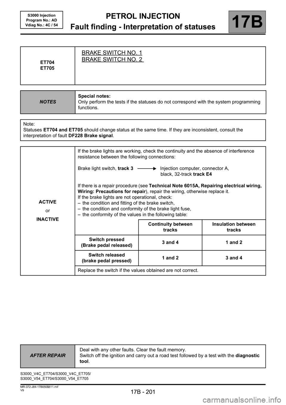
ET704
ET705
BRAKE SWITCH NO. 1
BRAKE SWITCH NO. 2
NOTESSpecial notes:
Only perform the tests if the statuses do not correspond with the system programming
functions.
Note:
Statuses ET704 and ET705 should change status at the same time. If they are inconsistent, consult the
interpretation of fault DF228 Brake signal.
ACTIVE
or
INACTIVEIf the brake lights are working, check the continuity and the absence of interference
resistance between the following connections:
Brake light switch, track 3 Injection computer, connector A,
black, 32-track track E4
If there is a repair procedure (see Technical Note 6015A, Repairing electrical wiring,
Wiring: Precautions for repair), repair the wiring, otherwise replace it.
If the brake lights are not operational, check:
– the condition and fitting of the brake switch,
– the condition and conformity of the brake light fuse,
– the conformity of the values in the following table:
Continuity between
tracksInsulation between
tracks
Switch pressed
(Brake pedal released)3 and 4 1 and 2
Switch released
(brake pedal pressed)1 and 2 3 and 4
Replace the switch if the values obtained are not correct.
AFTER REPAIRDeal with any other faults. Clear the fault memory.
Switch off the ignition and carry out a road test followed by a test with the diagnostic
tool.
S3000_V4C_ET704/S3000_V4C_ET705/
S3000_V54_ET704/S3000_V54_ET705
Page 202 of 230

PETROL INJECTION
17B
17B - 202
17B
17B - 202V9 MR-372-J84-17B050$658.mif
S3000 Injection
Program No.: AD
Vdiag No.: 4C / 54PETROL INJECTION
Fault finding - Parameter summary table
* OCR: Opening Cycle Ratio
* appli.: applicationTool parameter Diagnostic tool title
PR010Idling speed regulation setpoint
PR014Idling speed correction
PR018Estimated air flow
PR030Accelerator pedal position
PR035Atmospheric pressure
PR037Refrigerant pressure
PR055Engine speed
PR058Air temperature
PR064Coolant temperature
PR074Battery voltage
PR089Vehicle speed
PR090Idling speed regulation programming value
PR091OCR* Theoretical idle speed regulation
PR093Camshaft dephaser measured position
PR095Anti-pinking correction
PR096Motorised throttle upper stop programmed value
PR097Motorised throttle lower stop programmed value
PR098Upstream oxygen sensor voltage
PR099Downstream oxygen sensor voltage
PR101Duration of injection
PR102Canister bleed solenoid valve OCR*
PR103Instantaneous fuel consumption
PR105OBD fault warning light lit mileage counter
PR106Mileage counter fault warning light lit
PR111Motorised throttle position corrected value
PR113Throttle lower stop after offset appli.*
PR116Motorised throttle corrected position setpoint
MR-372-J84-17B050$658.mif
Page 206 of 230
PETROL INJECTION
Fault finding - Interpretation of parameters
17B
17B - 206
PETROL INJECTION
Fault finding - Interpretation of parameters
17B
17B - 206V9 MR-372-J84-17B050$705.mif
S3000 Injection
Program No.: AD
Vdiag No.: 4C / 54
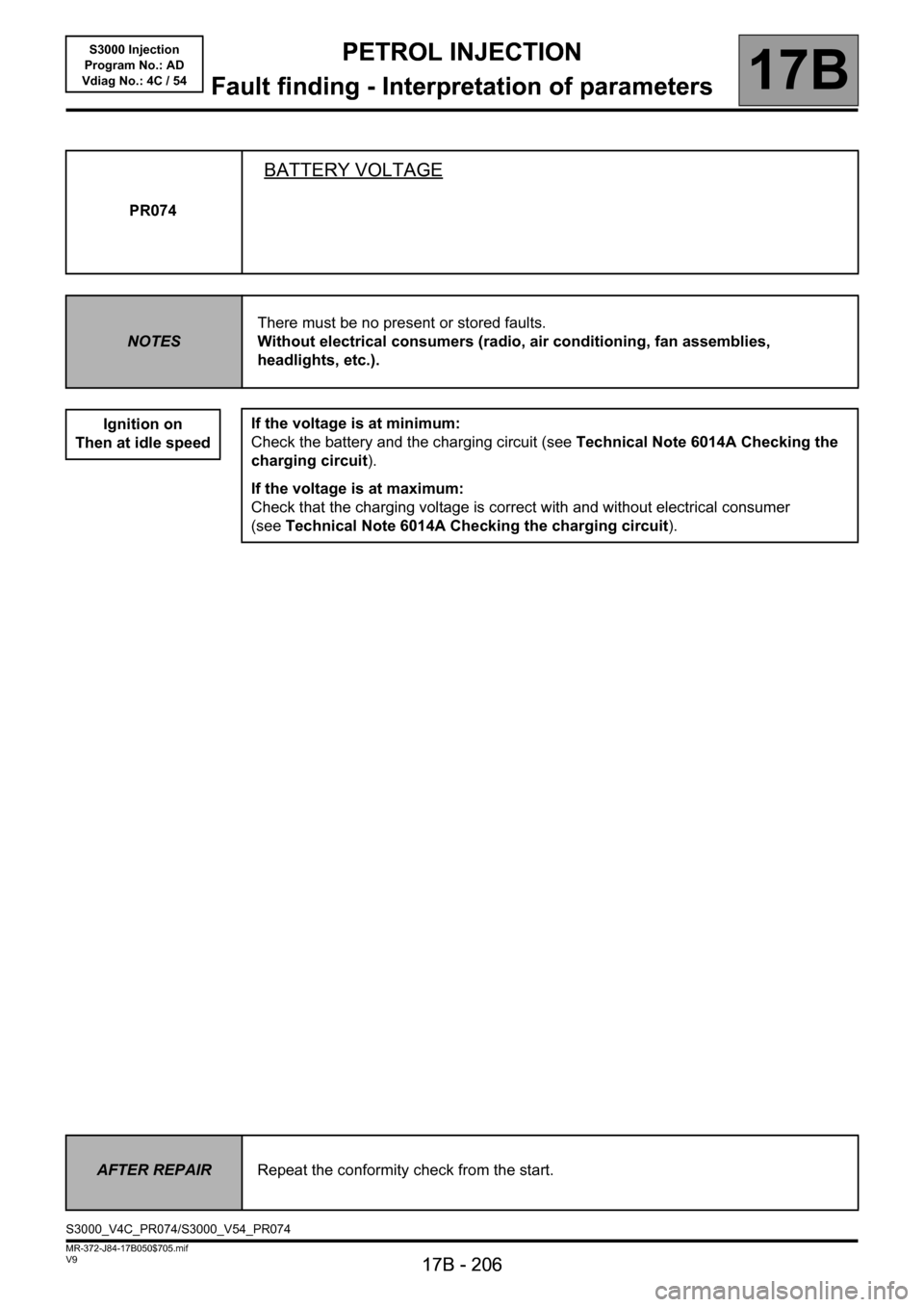
PR074
BATTERY VOLTAGE
NOTESThere must be no present or stored faults.
Without electrical consumers (radio, air conditioning, fan assemblies,
headlights, etc.).
Ignition on
Then at idle speed
If the voltage is at minimum:
Check the battery and the charging circuit (see Technical Note 6014A Checking the
charging circuit).
If the voltage is at maximum:
Check that the charging voltage is correct with and without electrical consumer
(seeTechnical Note 6014A Checking the charging circuit).
AFTER REPAIRRepeat the conformity check from the start.
S3000_V4C_PR074/S3000_V54_PR074
Page 225 of 230
PETROL INJECTION
Fault finding - Fault Finding Chart
17B
17B-225
PETROL INJECTION
Fault finding - Fault Finding Chart
17B
17B-225V9 MR-372-J84-17B050$940.mif
S3000 Injection
Program No.: AD
Vdiag No.:4C / 54PETROL INJECTION
Fault finding - Fault Finding Chart
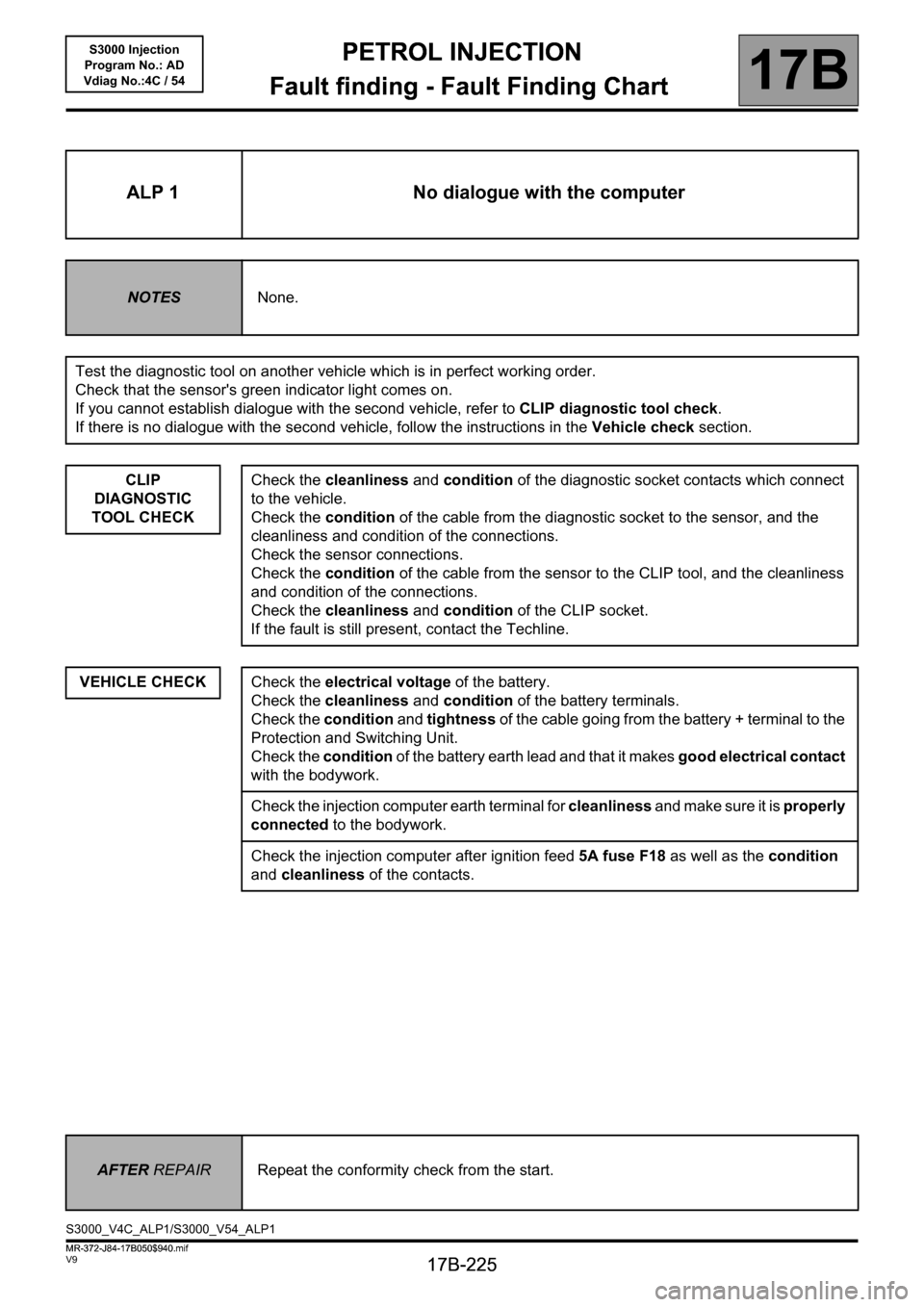
ALP 1 No dialogue with the computer
NOTESNone.
Test the diagnostic tool on another vehicle which is in perfect working order.
Check that the sensor's green indicator light comes on.
If you cannot establish dialogue with the second vehicle, refer to CLIP diagnostic tool check.
If there is no dialogue with the second vehicle, follow the instructions in the Vehicle check section.
CLIP
DIAGNOSTIC
TOOL CHECK
VEHICLE CHECK
Check the cleanliness and condition of the diagnostic socket contacts which connect
to the vehicle.
Check the condition of the cable from the diagnostic socket to the sensor, and the
cleanliness and condition of the connections.
Check the sensor connections.
Check the condition of the cable from the sensor to the CLIP tool, and the cleanliness
and condition of the connections.
Check the cleanliness and condition of the CLIP socket.
If the fault is still present, contact the Techline.
Check the electrical voltage of the battery.
Check the cleanliness and condition of the battery terminals.
Check the condition and tightness of the cable going from the battery + terminal to the
Protection and Switching Unit.
Check the condition of the battery earth lead and that it makes good electrical contact
with the bodywork.
Check the injection computer earth terminal for cleanliness and make sure it is properly
connected to the bodywork.
Check the injection computer after ignition feed 5A fuse F18 as well as the condition
and cleanliness of the contacts.
AFTER REPAIRRepeat the conformity check from the start.
S3000_V4C_ALP1/S3000_V54_ALP1
MR-372-J84-17B050$940.mif