light RENAULT SCENIC 2010 J95 / 3.G Petrol Injection S3000 Injection Repair Manual
[x] Cancel search | Manufacturer: RENAULT, Model Year: 2010, Model line: SCENIC, Model: RENAULT SCENIC 2010 J95 / 3.GPages: 230, PDF Size: 0.92 MB
Page 108 of 230
PETROL INJECTION
Fault finding - Interpretation of faults
17B
17B-108
PETROL INJECTION
Fault finding - Interpretation of faults
17B
17B-108V9 MR-372-J84-17B050$423.mif
S3000 Injection
Program No.: AD
Vdiag No.: 4C / 54
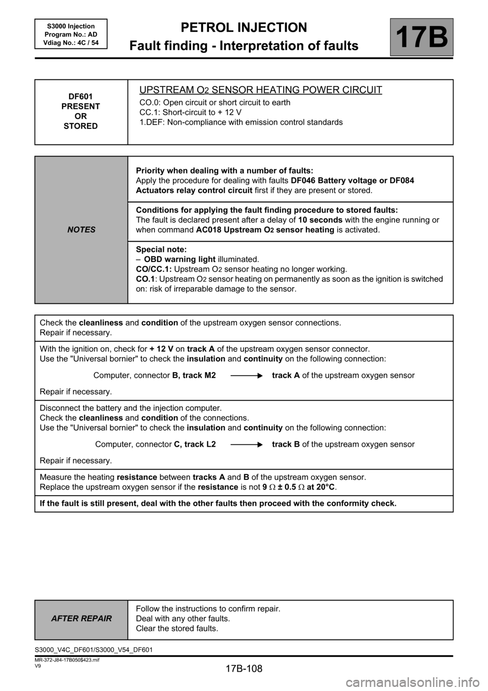
DF601
PRESENT
OR
STOREDUPSTREAM O2 SENSOR HEATING POWER CIRCUIT
CO.0: Open circuit or short circuit to earth
CC.1: Short-circuit to + 12 V
1.DEF: Non-compliance with emission control standards
NOTESPriority when dealing with a number of faults:
Apply the procedure for dealing with faults DF046 Battery voltage or DF084
Actuators relay control circuit first if they are present or stored.
Conditions for applying the fault finding procedure to stored faults:
The fault is declared present after a delay of 10 seconds with the engine running or
when command AC018 Upstream O2 sensor heating is activated.
Special note:
–OBD warning light illuminated.
CO/CC.1: Upstream O
2 sensor heating no longer working.
CO.1: Upstream O
2 sensor heating on permanently as soon as the ignition is switched
on: risk of irreparable damage to the sensor.
Check the cleanliness and condition of the upstream oxygen sensor connections.
Repair if necessary.
With the ignition on, check for + 12 V on track A of the upstream oxygen sensor connector.
Use the "Universal bornier" to check the insulation and continuity on the following connection:
Computer, connectorB, track M2 track A of the upstream oxygen sensor
Repair if necessary.
Disconnect the battery and the injection computer.
Check the cleanliness and condition of the connections.
Use the "Universal bornier" to check the insulation and continuity on the following connection:
Computer, connectorC, track L2 track B of the upstream oxygen sensor
Repair if necessary.
Measure the heating resistance between tracks A and B of the upstream oxygen sensor.
Replace the upstream oxygen sensor if the resistance is not 9Ω ± 0.5Ω at 20°C.
If the fault is still present, deal with the other faults then proceed with the conformity check.
AFTER REPAIRFollow the instructions to confirm repair.
Deal with any other faults.
Clear the stored faults.
S3000_V4C_DF601/S3000_V54_DF601
Page 109 of 230
PETROL INJECTION
Fault finding - Interpretation of faults
17B
17B-109
PETROL INJECTION
Fault finding - Interpretation of faults
17B
17B-109V9 MR-372-J84-17B050$423.mif
S3000 Injection
Program No.: AD
Vdiag No.: 4C / 54
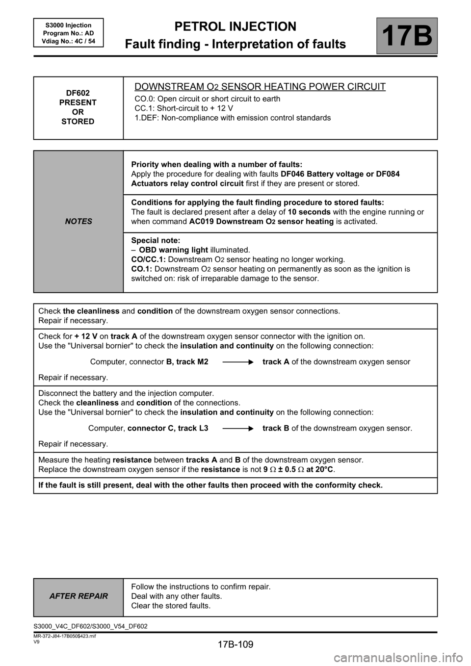
DF602
PRESENT
OR
STOREDDOWNSTREAM O2 SENSOR HEATING POWER CIRCUIT
CO.0: Open circuit or short circuit to earth
CC.1: Short-circuit to + 12 V
1.DEF: Non-compliance with emission control standards
NOTESPriority when dealing with a number of faults:
Apply the procedure for dealing with faults DF046 Battery voltage or DF084
Actuators relay control circuit first if they are present or stored.
Conditions for applying the fault finding procedure to stored faults:
The fault is declared present after a delay of 10 seconds with the engine running or
when command AC019 Downstream O2 sensor heating is activated.
Special note:
–OBD warning light illuminated.
CO/CC.1: Downstream O
2 sensor heating no longer working.
CO.1: Downstream O
2 sensor heating on permanently as soon as the ignition is
switched on: risk of irreparable damage to the sensor.
Check the cleanliness and condition of the downstream oxygen sensor connections.
Repair if necessary.
Check for + 12 V on track A of the downstream oxygen sensor connector with the ignition on.
Use the "Universal bornier" to check the insulation and continuity on the following connection:
Computer, connectorB, track M2 track A of the downstream oxygen sensor
Repair if necessary.
Disconnect the battery and the injection computer.
Check the cleanliness and condition of the connections.
Use the "Universal bornier" to check the insulation and continuity on the following connection:
Computer, connector C, track L3 track Bof the downstream oxygen sensor.
Repair if necessary.
Measure the heating resistance between tracks A and B of the downstream oxygen sensor.
Replace the downstream oxygen sensor if the resistance is not 9Ω ± 0.5Ω at 20°C.
If the fault is still present, deal with the other faults then proceed with the conformity check.
AFTER REPAIRFollow the instructions to confirm repair.
Deal with any other faults.
Clear the stored faults.
S3000_V4C_DF602/S3000_V54_DF602
Page 112 of 230
PETROL INJECTION
Fault finding - Interpretation of faults
17B
17B-112V9 MR-372-J84-17B050$423.mif
S3000 Injection
Program No.: AD
Vdiag No.: 4C / 54
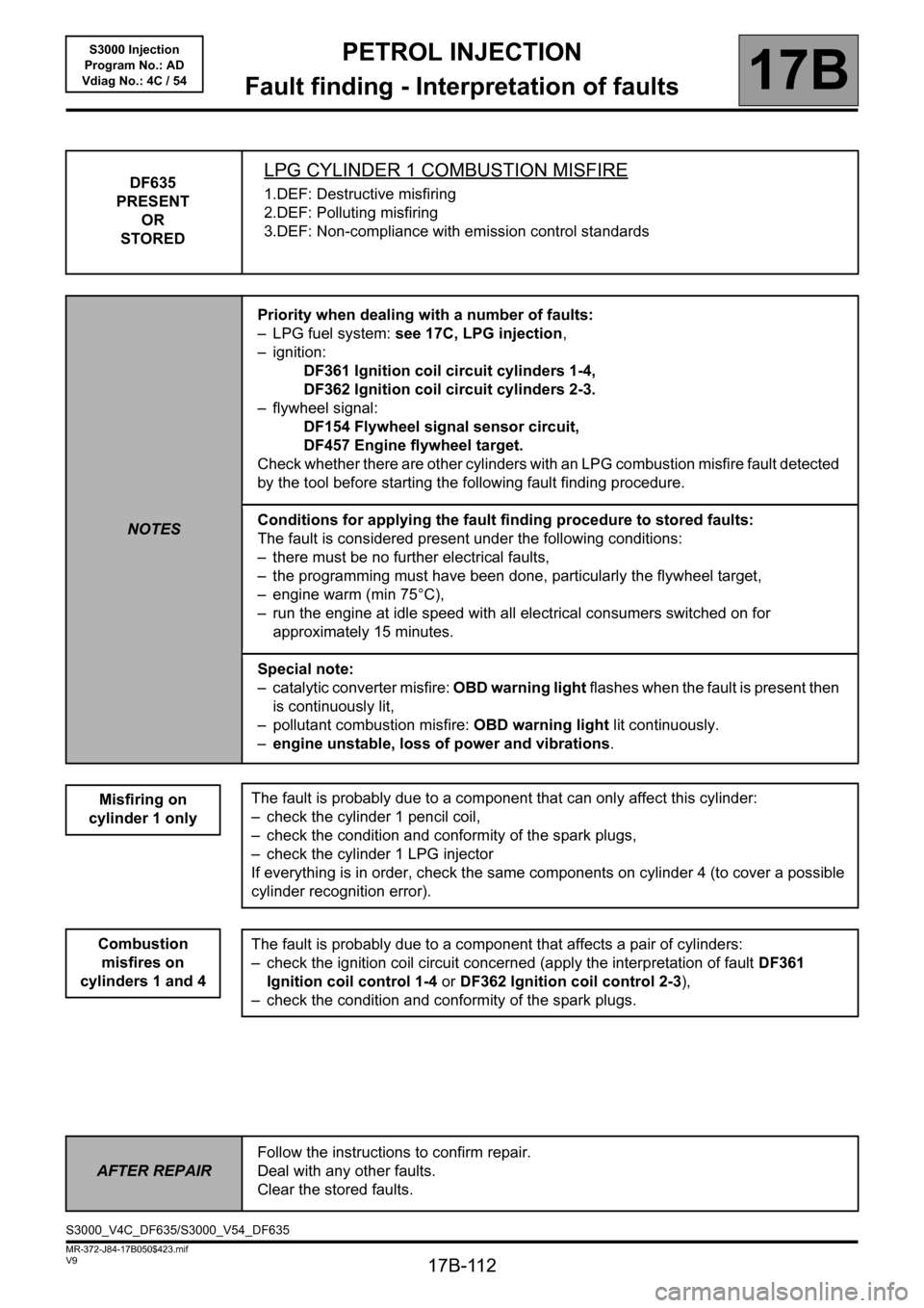
DF635
PRESENT
OR
STOREDLPG CYLINDER 1 COMBUSTION MISFIRE
1.DEF: Destructive misfiring
2.DEF: Polluting misfiring
3.DEF: Non-compliance with emission control standards
NOTESPriority when dealing with a number of faults:
– LPG fuel system: see 17C, LPG injection,
– ignition:
DF361 Ignition coil circuit cylinders 1-4,
DF362 Ignition coil circuit cylinders 2-3.
– flywheel signal:
DF154 Flywheel signal sensor circuit,
DF457 Engine flywheel target.
Check whether there are other cylinders with an LPG combustion misfire fault detected
by the tool before starting the following fault finding procedure.
Conditions for applying the fault finding procedure to stored faults:
The fault is considered present under the following conditions:
– there must be no further electrical faults,
– the programming must have been done, particularly the flywheel target,
– engine warm (min 75°C),
– run the engine at idle speed with all electrical consumers switched on for
approximately 15 minutes.
Special note:
– catalytic converter misfire: OBD warning light flashes when the fault is present then
is continuously lit,
– pollutant combustion misfire: OBD warning light lit continuously.
–engine unstable, loss of power and vibrations.
Misfiring on
cylinder 1 only
Combustion
misfires on
cylinders 1 and 4
The fault is probably due to a component that can only affect this cylinder:
– check the cylinder 1 pencil coil,
– check the condition and conformity of the spark plugs,
– check the cylinder 1 LPG injector
If everything is in order, check the same components on cylinder 4 (to cover a possible
cylinder recognition error).
The fault is probably due to a component that affects a pair of cylinders:
– check the ignition coil circuit concerned (apply the interpretation of fault DF361
Ignition coil control 1-4 or DF362 Ignition coil control 2-3),
– check the condition and conformity of the spark plugs.
AFTER REPAIRFollow the instructions to confirm repair.
Deal with any other faults.
Clear the stored faults.
S3000_V4C_DF635/S3000_V54_DF635
Page 113 of 230
PETROL INJECTION
Fault finding - Interpretation of faults
17B
17B-113V9 MR-372-J84-17B050$423.mif
S3000 Injection
Program No.: AD
Vdiag No.: 4C / 54
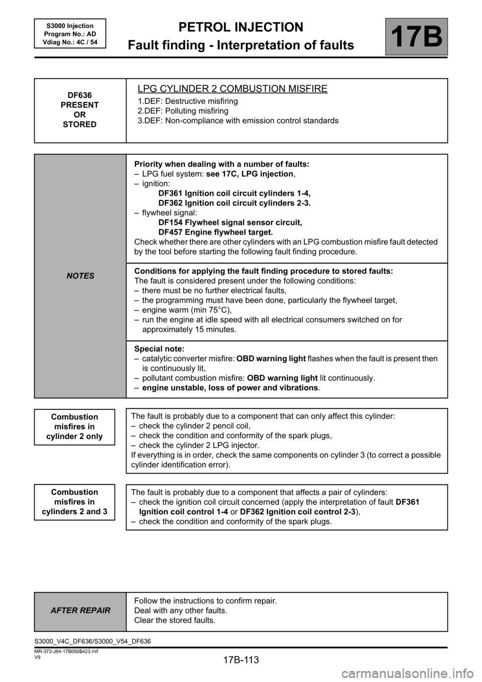
DF636
PRESENT
OR
STOREDLPG CYLINDER 2 COMBUSTION MISFIRE
1.DEF: Destructive misfiring
2.DEF: Polluting misfiring
3.DEF: Non-compliance with emission control standards
NOTESPriority when dealing with a number of faults:
– LPG fuel system: see 17C, LPG injection,
– ignition:
DF361 Ignition coil circuit cylinders 1-4,
DF362 Ignition coil circuit cylinders 2-3.
– flywheel signal:
DF154 Flywheel signal sensor circuit,
DF457 Engine flywheel target.
Check whether there are other cylinders with an LPG combustion misfire fault detected
by the tool before starting the following fault finding procedure.
Conditions for applying the fault finding procedure to stored faults:
The fault is considered present under the following conditions:
– there must be no further electrical faults,
– the programming must have been done, particularly the flywheel target,
– engine warm (min 75°C),
– run the engine at idle speed with all electrical consumers switched on for
approximately 15 minutes.
Special note:
– catalytic converter misfire: OBD warning light flashes when the fault is present then
is continuously lit,
– pollutant combustion misfire: OBD warning light lit continuously.
–engine unstable, loss of power and vibrations.
Combustion
misfires in
cylinder 2 only
Combustion
misfires in
cylinders 2 and 3
The fault is probably due to a component that can only affect this cylinder:
– check the cylinder 2 pencil coil,
– check the condition and conformity of the spark plugs,
– check the cylinder 2 LPG injector.
If everything is in order, check the same components on cylinder 3 (to correct a possible
cylinder identification error).
The fault is probably due to a component that affects a pair of cylinders:
– check the ignition coil circuit concerned (apply the interpretation of fault DF361
Ignition coil control 1-4 or DF362 Ignition coil control 2-3),
– check the condition and conformity of the spark plugs.
AFTER REPAIRFollow the instructions to confirm repair.
Deal with any other faults.
Clear the stored faults.
S3000_V4C_DF636/S3000_V54_DF636
Page 114 of 230
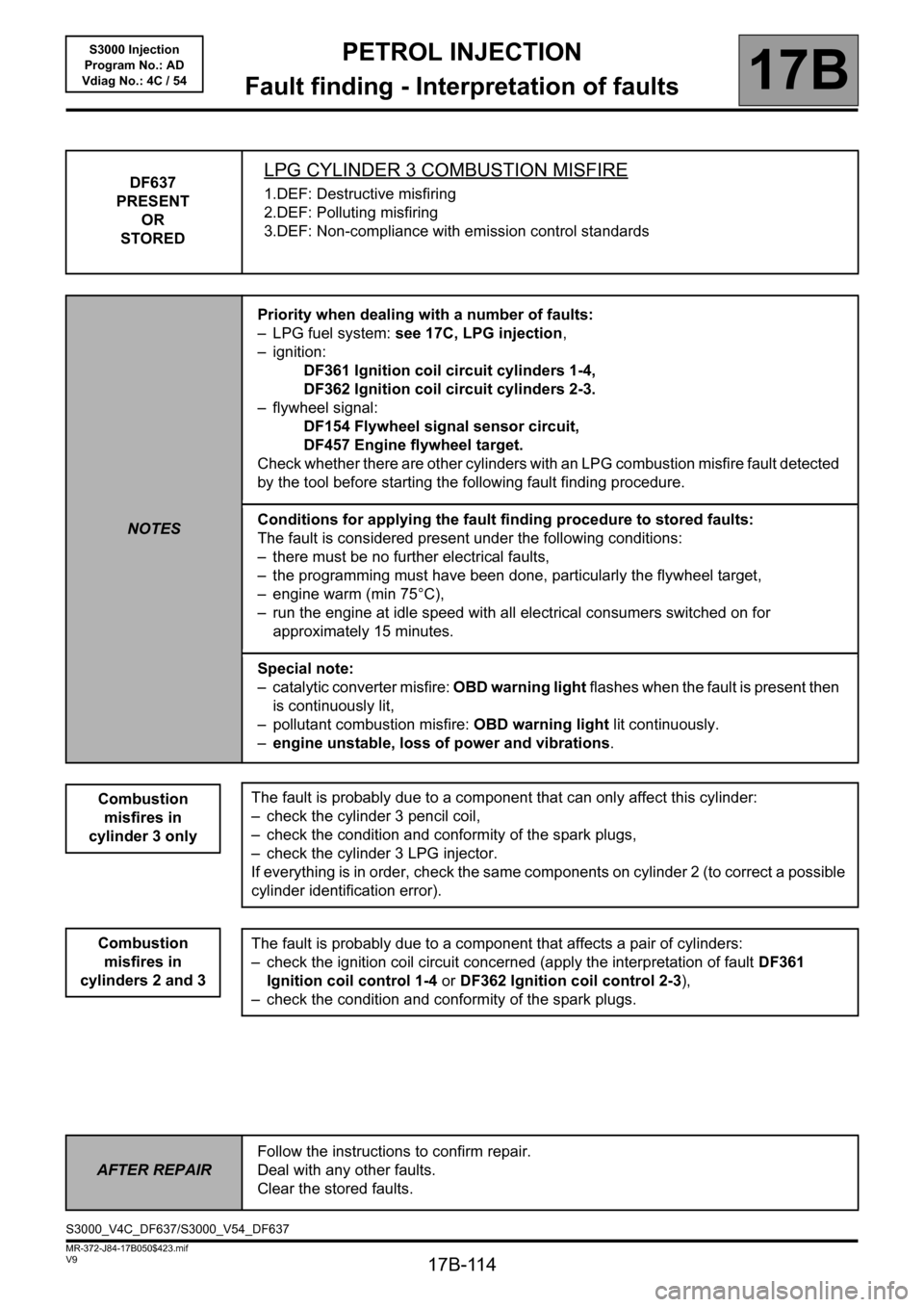
PETROL INJECTION
Fault finding - Interpretation of faults
17B
17B-114V9 MR-372-J84-17B050$423.mif
S3000 Injection
Program No.: AD
Vdiag No.: 4C / 54
DF637
PRESENT
OR
STOREDLPG CYLINDER 3 COMBUSTION MISFIRE
1.DEF: Destructive misfiring
2.DEF: Polluting misfiring
3.DEF: Non-compliance with emission control standards
NOTESPriority when dealing with a number of faults:
– LPG fuel system: see 17C, LPG injection,
– ignition:
DF361 Ignition coil circuit cylinders 1-4,
DF362 Ignition coil circuit cylinders 2-3.
– flywheel signal:
DF154 Flywheel signal sensor circuit,
DF457 Engine flywheel target.
Check whether there are other cylinders with an LPG combustion misfire fault detected
by the tool before starting the following fault finding procedure.
Conditions for applying the fault finding procedure to stored faults:
The fault is considered present under the following conditions:
– there must be no further electrical faults,
– the programming must have been done, particularly the flywheel target,
– engine warm (min 75°C),
– run the engine at idle speed with all electrical consumers switched on for
approximately 15 minutes.
Special note:
– catalytic converter misfire: OBD warning light flashes when the fault is present then
is continuously lit,
– pollutant combustion misfire: OBD warning light lit continuously.
–engine unstable, loss of power and vibrations.
Combustion
misfires in
cylinder 3 only
Combustion
misfires in
cylinders 2 and 3
The fault is probably due to a component that can only affect this cylinder:
– check the cylinder 3 pencil coil,
– check the condition and conformity of the spark plugs,
– check the cylinder 3 LPG injector.
If everything is in order, check the same components on cylinder 2 (to correct a possible
cylinder identification error).
The fault is probably due to a component that affects a pair of cylinders:
– check the ignition coil circuit concerned (apply the interpretation of fault DF361
Ignition coil control 1-4 or DF362 Ignition coil control 2-3),
– check the condition and conformity of the spark plugs.
AFTER REPAIRFollow the instructions to confirm repair.
Deal with any other faults.
Clear the stored faults.
S3000_V4C_DF637/S3000_V54_DF637
Page 115 of 230
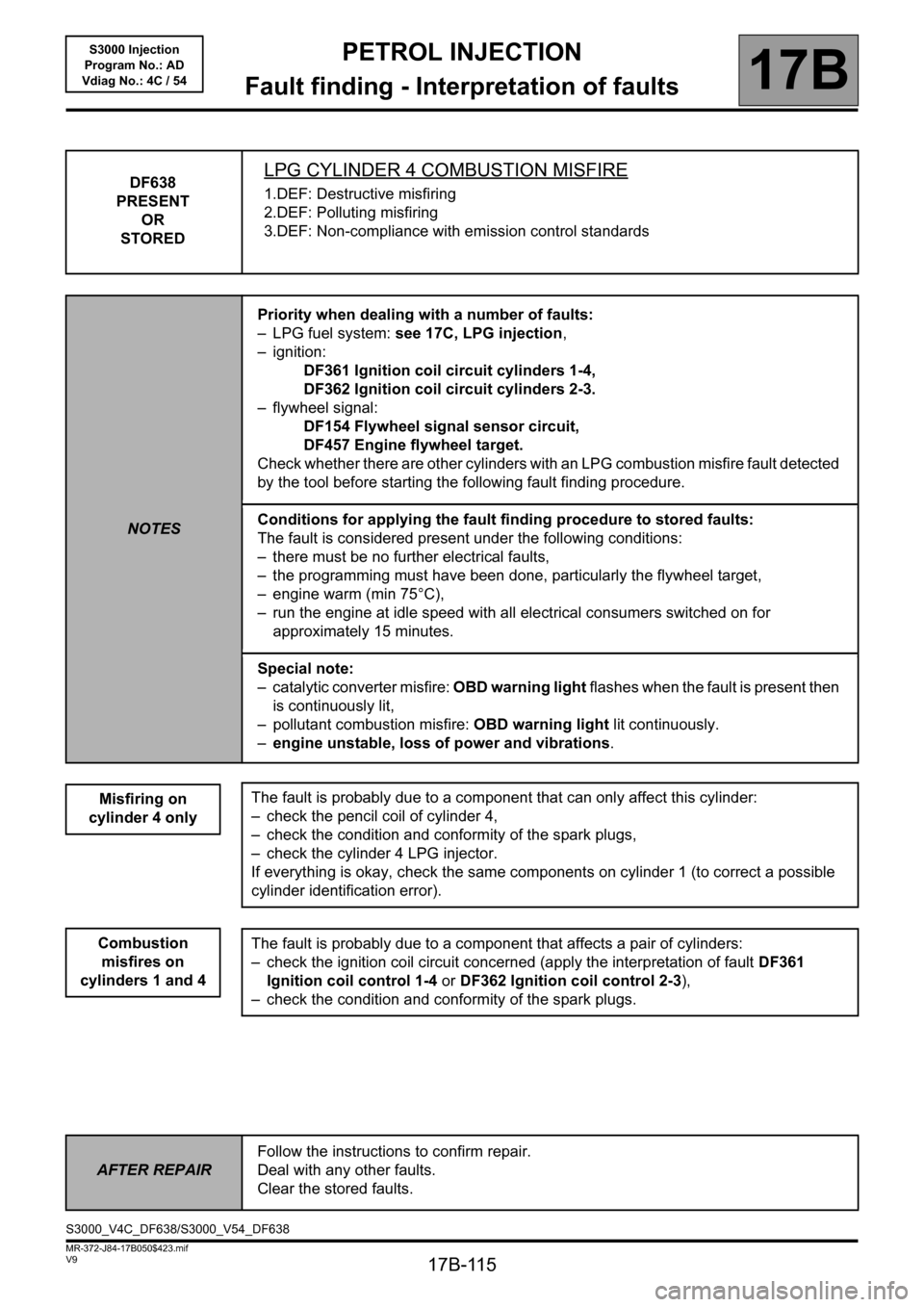
PETROL INJECTION
Fault finding - Interpretation of faults
17B
17B-115V9 MR-372-J84-17B050$423.mif
S3000 Injection
Program No.: AD
Vdiag No.: 4C / 54
DF638
PRESENT
OR
STOREDLPG CYLINDER 4 COMBUSTION MISFIRE
1.DEF: Destructive misfiring
2.DEF: Polluting misfiring
3.DEF: Non-compliance with emission control standards
NOTESPriority when dealing with a number of faults:
– LPG fuel system: see 17C, LPG injection,
– ignition:
DF361 Ignition coil circuit cylinders 1-4,
DF362 Ignition coil circuit cylinders 2-3.
– flywheel signal:
DF154 Flywheel signal sensor circuit,
DF457 Engine flywheel target.
Check whether there are other cylinders with an LPG combustion misfire fault detected
by the tool before starting the following fault finding procedure.
Conditions for applying the fault finding procedure to stored faults:
The fault is considered present under the following conditions:
– there must be no further electrical faults,
– the programming must have been done, particularly the flywheel target,
– engine warm (min 75°C),
– run the engine at idle speed with all electrical consumers switched on for
approximately 15 minutes.
Special note:
– catalytic converter misfire: OBD warning light flashes when the fault is present then
is continuously lit,
– pollutant combustion misfire: OBD warning light lit continuously.
–engine unstable, loss of power and vibrations.
Misfiring on
cylinder 4 only
Combustion
misfires on
cylinders 1 and 4
The fault is probably due to a component that can only affect this cylinder:
– check the pencil coil of cylinder 4,
– check the condition and conformity of the spark plugs,
– check the cylinder 4 LPG injector.
If everything is okay, check the same components on cylinder 1 (to correct a possible
cylinder identification error).
The fault is probably due to a component that affects a pair of cylinders:
– check the ignition coil circuit concerned (apply the interpretation of fault DF361
Ignition coil control 1-4 or DF362 Ignition coil control 2-3),
– check the condition and conformity of the spark plugs.
AFTER REPAIRFollow the instructions to confirm repair.
Deal with any other faults.
Clear the stored faults.
S3000_V4C_DF638/S3000_V54_DF638
Page 116 of 230
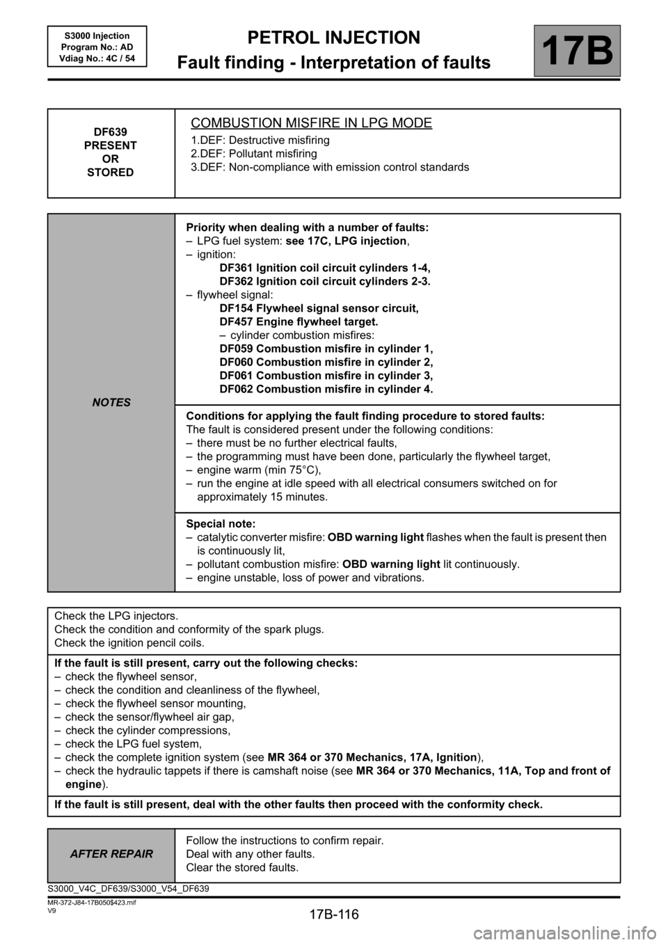
PETROL INJECTION
Fault finding - Interpretation of faults
17B
17B-116
PETROL INJECTION
Fault finding - Interpretation of faults
17B
17B-116V9 MR-372-J84-17B050$423.mif
S3000 Injection
Program No.: AD
Vdiag No.: 4C / 54
DF639
PRESENT
OR
STOREDCOMBUSTION MISFIRE IN LPG MODE
1.DEF: Destructive misfiring
2.DEF: Pollutant misfiring
3.DEF: Non-compliance with emission control standards
NOTESPriority when dealing with a number of faults:
– LPG fuel system: see 17C, LPG injection,
– ignition:
DF361 Ignition coil circuit cylinders 1-4,
DF362 Ignition coil circuit cylinders 2-3.
– flywheel signal:
DF154 Flywheel signal sensor circuit,
DF457 Engine flywheel target.
– cylinder combustion misfires:
DF059 Combustion misfire in cylinder 1,
DF060 Combustion misfire in cylinder 2,
DF061 Combustion misfire in cylinder 3,
DF062 Combustion misfire in cylinder 4.
Conditions for applying the fault finding procedure to stored faults:
The fault is considered present under the following conditions:
– there must be no further electrical faults,
– the programming must have been done, particularly the flywheel target,
– engine warm (min 75°C),
– run the engine at idle speed with all electrical consumers switched on for
approximately 15 minutes.
Special note:
– catalytic converter misfire: OBD warning light flashes when the fault is present then
is continuously lit,
– pollutant combustion misfire: OBD warning light lit continuously.
– engine unstable, loss of power and vibrations.
Check the LPG injectors.
Check the condition and conformity of the spark plugs.
Check the ignition pencil coils.
If the fault is still present, carry out the following checks:
– check the flywheel sensor,
– check the condition and cleanliness of the flywheel,
– check the flywheel sensor mounting,
– check the sensor/flywheel air gap,
– check the cylinder compressions,
– check the LPG fuel system,
– check the complete ignition system (see MR 364 or 370 Mechanics, 17A, Ignition),
– check the hydraulic tappets if there is camshaft noise (see MR 364 or 370 Mechanics, 11A, Top and front of
engine).
If the fault is still present, deal with the other faults then proceed with the conformity check.
AFTER REPAIRFollow the instructions to confirm repair.
Deal with any other faults.
Clear the stored faults.
S3000_V4C_DF639/S3000_V54_DF639
Page 117 of 230
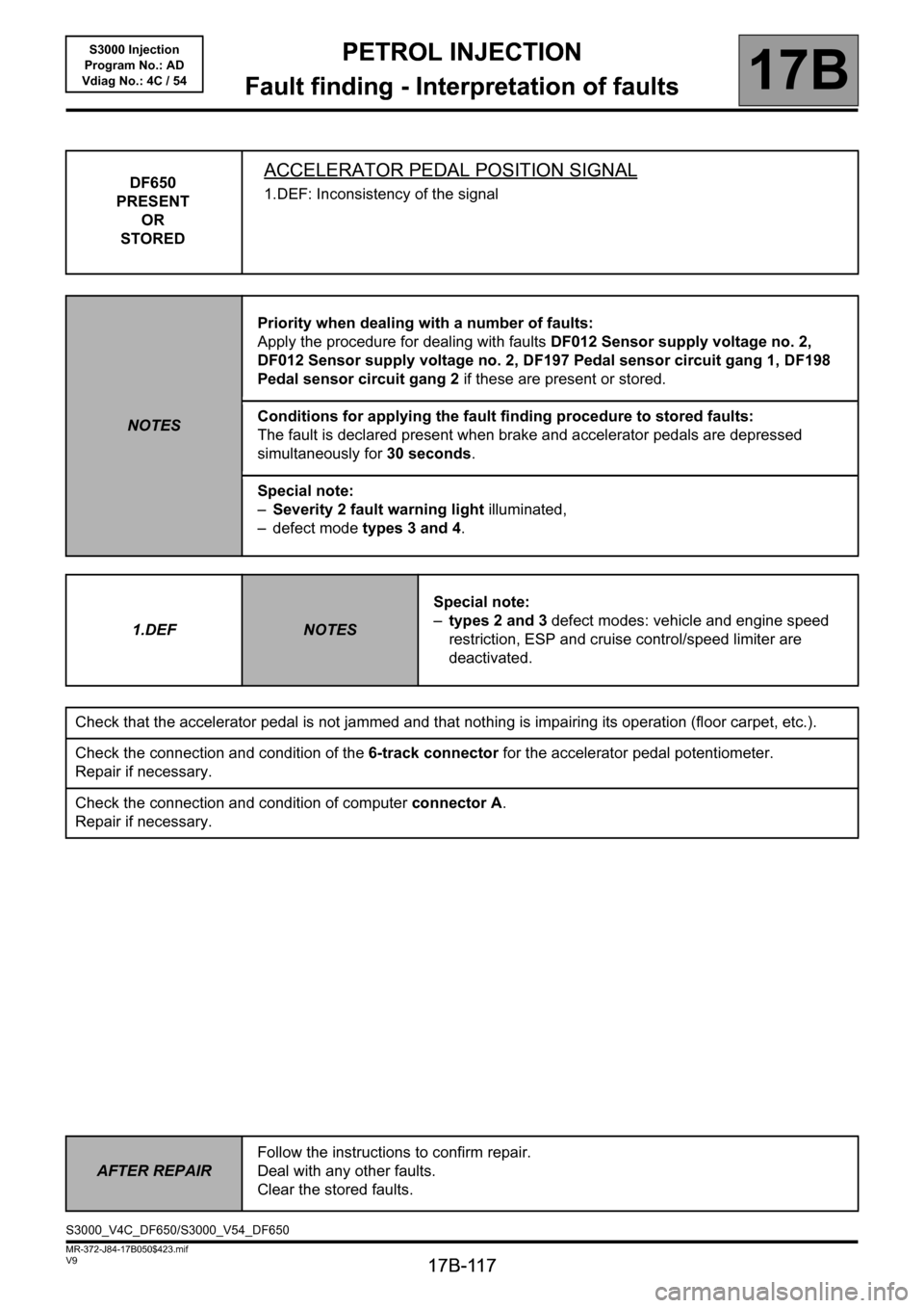
PETROL INJECTION
Fault finding - Interpretation of faults
17B
17B-117
PETROL INJECTION
Fault finding - Interpretation of faults
17B
17B-117V9 MR-372-J84-17B050$423.mif
S3000 Injection
Program No.: AD
Vdiag No.: 4C / 54
DF650
PRESENT
OR
STOREDACCELERATOR PEDAL POSITION SIGNAL
1.DEF: Inconsistency of the signal
NOTESPriority when dealing with a number of faults:
Apply the procedure for dealing with faults DF012 Sensor supply voltage no. 2,
DF012 Sensor supply voltage no. 2, DF197 Pedal sensor circuit gang 1, DF198
Pedal sensor circuit gang 2 if these are present or stored.
Conditions for applying the fault finding procedure to stored faults:
The fault is declared present when brake and accelerator pedals are depressed
simultaneously for 30 seconds.
Special note:
–Severity 2 fault warning light illuminated,
– defect mode types 3 and 4.
1.DEF
NOTESSpecial note:
–types 2 and 3 defect modes: vehicle and engine speed
restriction, ESP and cruise control/speed limiter are
deactivated.
Check that the accelerator pedal is not jammed and that nothing is impairing its operation (floor carpet, etc.).
Check the connection and condition of the 6-track connector for the accelerator pedal potentiometer.
Repair if necessary.
Check the connection and condition of computer connector A.
Repair if necessary.
AFTER REPAIRFollow the instructions to confirm repair.
Deal with any other faults.
Clear the stored faults.
S3000_V4C_DF650/S3000_V54_DF650
Page 120 of 230

PETROL INJECTION
Fault finding - Conformity check
17B
17B-120
PETROL INJECTION
Fault finding - Conformity check
17B
17B-120V9 MR-372-J84-17B050$470.mif
S3000 Injection
Program No.: AD
Vdiag No.: 4C / 54PETROL INJECTION
Fault finding - Conformity check
MAIN COMPUTER STATUSES AND PARAMETERS
NOTESOnly check the conformity after a complete check with the diagnostic tool. The values
shown in this conformity check are given as a guide.
Application conditions: engine stopped, ignition on.
Order FunctionParameter or Status Checked
or ActionDisplay and notes Fault finding
1
Battery voltageET001:Computer + after
ignition feedPresentIn the event of a fault,
apply the
interpretation of
DF046 Battery
voltage. 2 PR074:Battery voltage11 V < PR074 < 15 V
3 Vehicle speed PR089:Vehicle speedGives the vehicle
speed in mph (km/h).
This parameter is
sent to the injection
by the ABS computer
via the multiplex
network.
PR089= 0mphIn the event of a fault
apply the
interpretation for
DF091 Vehicle speed
signal.
4
FaultsET064:Level 1 injection faultYES
NO
WITHOUT 5ET065:Level 2 Injection faultYES
NO
6 PR105:OBD fault warning
light lit mileage
counterIndicates the mileage
covered with the
OBD warning light lit.
7 PR106:Mileage counter fault
warning light litShows the distance
covered with the
warning light lit.
S3000_V4C_CCONF/S3000_V54_CCONF
MR-372-J84-17B050$470.mif
Page 128 of 230

PETROL INJECTION
Fault finding - Conformity check
17B
17B-128
PETROL INJECTION
Fault finding - Conformity check
17B
17B-128V9 MR-372-J84-17B050$470.mif
S3000 Injection
Program No.: AD
Vdiag No.: 4C / 54
EMISSION CONTROL / OBD SUBFUNCTION (cont.):
NOTESOnly check the conformity after a complete check with the diagnostic tool. The values
shown in this conformity check are given as a guide.
Application conditions: Engine off, ignition on.
Order FunctionParameter or Status Checked
or ActionDisplay and notes Fault finding
7
Oxygen sensorET052:Upstream O
2 sensor
heatingINACTIVEIn the event of a fault
apply the interpretation of
DF601 Upstream
oxygen sensor heating
power circuit.
8ET053:Downstream O
2
sensor heatingINACTIVEIn the event of a fault,
apply interpretation of
DF602 Downstream
oxygen sensor heating
power circuit.
9CanisterAC017:Canister bleed
solenoid valveThe canister
bleed solenoid
valve should be
heard running.In the event of a fault,
apply interpretation of
DF549 Canister bleed
circuit.
10
Fault findingET617:Upstream oxygen
sensor OBD fault
findingINACTIVE None
11 ET619:Fuel circuit OBD fault
findingINACTIVE None
12 ET581:Petrol combustion
misfire fault findingINACTIVE None
13 Fault finding ET340:Request by automatic
transmission to light
up the OBD warning
lightINACTIVEIf ACTIVE, apply the
interpretation of fault
DF099 Automatic
gearbox or sequential
gearbox connection via
the multiplex network.
14
RichnessET300:Richness regulationACTIVE
INACTIVEWITHOUT
15 ET056:Richness double loopACTIVE
INACTIVEIn the event of a fault,
apply the interpretation of
ET056 Double richness
loop.